Page 282 of 3870
Fig. 3: Identifying Driver
-side Air Bag Module & Clockspring (Single
-stage
Air Bag System)
Courtesy of MITSUBISHI MOTOR SALES OF AMERICA.
Removal & Installation (With Dual Stage AIR Bag System) 1. Before proceeding, see
AIR BAG SAFETY PRECAUTIONS
. Ensure front
wheels are in straight-ahead position. Turn ignition off. Disable air bag system.
See
DISABLING & ACTIVATING AIR BAG SYSTEM
.
2. Remove lower cover from steering wheel. Remove driver-side air bag module
bolts from rear of steering wheel. Remove driver-side air bag module. See Fig.
4 . Remove damper weight from steering wheel. Remove steering wheel nut
and discard. Using Steering Wheel Puller (MB990803), remove steering wheel.
3. Remove upper and lower steering column covers. Disconnect clockspring
electrical connectors. Remove clocks
prin
g screws. Remove clocks
prin
g from
2004 Mitsubishi Endeavor Limited
2004 ACCESSORIES/SAFETY EQUIPMENT Mitsubishi - Air Bag Restraint Systems
Page 283 of 3870
steering column.
4. To install, reverse removal procedure. If necessary, center clockspring. See
CENTERING CLOCKSPRING
under ADJUSTMENTS. Tighten
clockspring screws, NEW steering wheel nut and driver-side air bag module
bolts to specification. See TORQUE SPECIFICATIONS
. Activate air bag
system.
Fig. 4: Identifying Driver
-side Air Bag Module & Clockspring (Dual
-stage Air
Bag System)
Courtesy of MITSUBISHI MOTOR SALES OF AMERICA.
FLOOR CONSOLE ASSEMBLY (WITH DUAL STAGE AIR BAG SYSTEM) Removal & Installation 1. Before proceeding, see AIR BAG SAFETY PRECAUTIONS
. Disable air
bag system. See DISABLING & ACTIVATING AIR BAG SYSTEM
.
2. Remove inner box tray. See Fig. 5
. Remove plate. Remove cup holder,
Remove left and right side covers. Remove gearshift lever panel. Remove
accessory panel. Remove rear A/C switch and accessory socket. Remove floor
console assembl
y.
2004 Mitsubishi Endeavor Limited
2004 ACCESSORIES/SAFETY EQUIPMENT Mitsubishi - Air Bag Restraint Systems
Page 292 of 3870

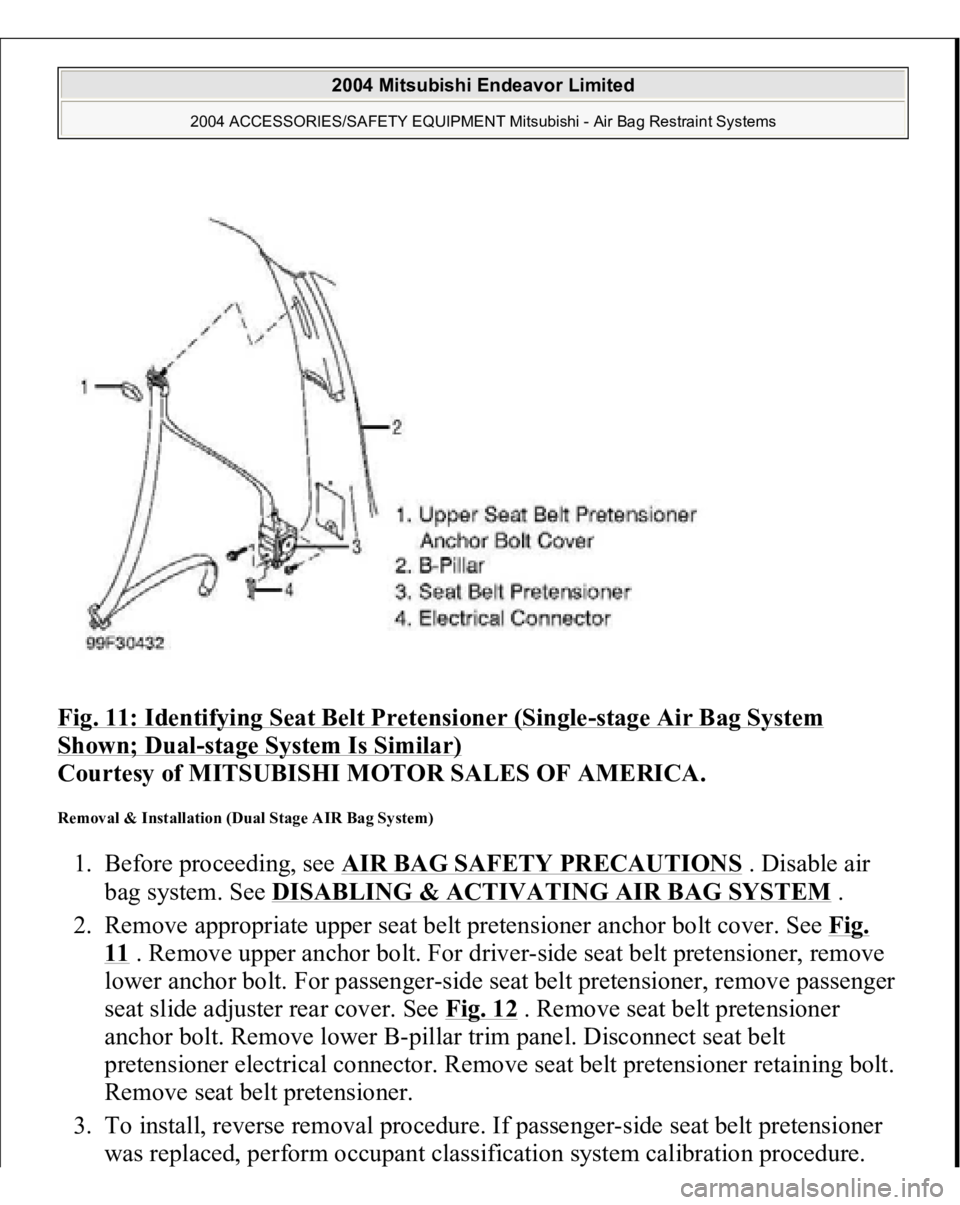
Fig. 11: Identifying Seat Belt Pretensioner (Single
-stage Air Bag System
Shown; Dual
-stage System Is Similar)
Courtesy of MITSUBISHI MOTOR SALES OF AMERICA.
Removal & Installation (Dual Stage AIR Bag System) 1. Before proceeding, see AIR BAG SAFETY PRECAUTIONS
. Disable air
bag system. See DISABLING & ACTIVATING AIR BAG SYSTEM
.
2. Remove appropriate upper seat belt pretensioner anchor bolt cover. See Fig.
11 . Remove upper anchor bolt. For driver-side seat belt pretensioner, remove
lower anchor bolt. For passenger-side seat belt pretensioner, remove passenger
seat slide adjuster rear cover. See Fig. 12
. Remove seat belt pretensioner
anchor bolt. Remove lower B-pillar trim panel. Disconnect seat belt
pretensioner electrical connector. Remove seat belt pretensioner retaining bolt.
Remove seat belt pretensioner.
3. To install, reverse removal procedure. If passenger-side seat belt pretensioner
was replaced, perform occupant classification system calibration procedure.
2004 Mitsubishi Endeavor Limited
2004 ACCESSORIES/SAFETY EQUIPMENT Mitsubishi - Air Bag Restraint Systems
Page 293 of 3870
See OCCUPANT CLASSIFICATION SENSOR CALIBRATION
under
COMPONENT TESTING. Tighten seat belt pretensioner anchor bolts to
specification. See TORQUE SPECIFICATIONS
. Activate air bag system.
Fig. 12: Identifying Passenger Seat Slide Adjuster Rear Cover (Dual
-stage Air
Bag System)
Courtesy of MITSUBISHI MOTOR SALES OF AMERICA.
SEAT SLIDE SENSOR (DUAL STAGE AIR BAG SYSTEM) Removal & Installation 1. Before proceeding, see AIR BAG SAFETY PRECAUTIONS
. Disable air
bag system. See DISABLING & ACTIVATING AIR BAG SYSTEM
.
2. Remove driver seat. Remove seat slide sensor bolt. See Fig. 13
. Remove seat
2004 Mitsubishi Endeavor Limited
2004 ACCESSORIES/SAFETY EQUIPMENT Mitsubishi - Air Bag Restraint Systems
Page 444 of 3870

1. Connect scan tool to Data Link Connector (DLC). See INITIAL SRS
DIAGNOSTIC PROCEDURE
under DIAGNOSTICS. If scan tool is able to
diagnose CAN bus lines and CAN bus lines are satisfactory, go to next step. If
scan tool cannot diagnose CAN bus lines, repair CAN bus lines. Go to next
step.
2. Erase, then retrieve DTCs. If DTC B1558 is retrieved, replace seat slide sensor.
See SEAT SLIDE SENSOR
under REMOVAL & INSTALLATION. If DTC
B1558 is not retrieved, an intermittent condition may exist.
DTC U1073: BUS OFF 1. Connect scan tool to Data Link Connector (DLC). See INITIAL SRS
DIAGNOSTIC PROCEDURE
under DIAGNOSTICS. If scan tool is able to
diagnose CAN bus lines and CAN bus lines are satisfactory, go to next step. If
scan tool cannot diagnose CAN bus lines, repair CAN bus lines. Go to next
step.
2. Erase, then retrieve DTCs. If scan tool retrieves DTC U1073, replace A/C
ECU. If scan tool does not retrieve DTC U1073, an intermittent condition may
exist.
COMPONENT TESTING OCCUPANT CLASSIFICATION SENSOR CALIBRATION (DUAL-STAGE AIR BAG SYSTEM) 1. Connect scan tool to Data Link Connector (DLC). See INITIAL SRS
DIAGNOSTIC PROCEDURE
under DIAGNOSTICS. Go to next step.
2. Open and close passenger-side front door 5 times hard to remove friction. If
door does not open and close smoothly after the impact, hit front and rear sides
of seat back about 8 times each to remove friction. Go to next step.
3. Select INTERACTIVE DIAGNOSIS, then SPECIAL FUNCTION then SEAT
WEIGHT SENSOR ACCURACY CHECK on screen. Slide passenger-side
front seat to full forward position. Place a 66 pound weight (30 kg) in center of
passenger-side seat cushion. Repeat step2 . Touch OK button to perform
accuracy check.
4. If variance between sensor output and input levels is within 11 pounds (5 kg),
ACCURACY CHECK COMPLETION will be dis
played on screen. Go to ste
p
2004 Mitsubishi Endeavor Limited
2004 ACCESSORIES/SAFETY EQUIPMENT Mitsubishi - Air Bag Restraint Systems
Page 445 of 3870

6 . If ACCURACY CHECK COMPLETION is not displayed, go to next step.
5. If ABNORMAL CONDITION is displayed, press OK and go to calibration
screen. Remove weight from seat. Verify seat is installed correctly. If seat is
installed correctly, go to step 1 .
6. Remove weight from seat cushion. Move seat to rear most position. Repeat
step2 . Go to next step.
7. Select INTERACTIVE DIAGNOSIS, then SPECIAL FUNCTION then SEAT
WEIGHT SENSOR ACCURACY CHECK on screen. Place a 66 pound weight
(30 kg) in center of passenger-side seat cushion. Repeat step2 . Touch OK
button to perform accuracy check. Go to next step.
8. If variance between sensor output and input levels is within 11 pounds (5 kg),
ACCURACY CHECK COMPLETION will be displayed on screen.
Calibration is complete. If ACCURACY CHECK COMPLETION is not
displayed, go to next step.
9. Verify seat is installed correctly. Repeat step2 . Touch OK button. When
EXECUTION prompt is displayed, touch OK button. When calibration is
completed, screen will display ZERO CALIBRATION COMPLETED. If
calibration cannot be completed, an intermittent condition may exist.
FRONT IMPACT SENSOR (DUAL-STAGE AIR BAG SYSTEM) 1. Remove appropriate front impact sensor. See FRONT IMPACT SENSOR
under REMOVAL & INSTALLATION. Visually inspect front impact sensor
case, connectors and brackets for damage. If no damage is found, go to next
step. If damage is found, discard front impact sensor.
2. Measure resistance between terminals of front impact sensor. Resistance
should be 738-902 ohms. Measure resistance between front impact sensor
terminals and front impact sensor case. Resistance should be infinite. If
resistance is not as specified, replace front impact sensor.
WIRING DIAGRAMS
2004 Mitsubishi Endeavor Limited
2004 ACCESSORIES/SAFETY EQUIPMENT Mitsubishi - Air Bag Restraint Systems
Page 456 of 3870

2004 TRANSMISSION
Automatic Transaxle Overhaul - Endeavor
GENERAL INFORMATION This automatic transaxle is made up of the following main parts.
The gear train is made up of 3 multi-plate clutches, 2 multi-plate brakes and 2
planetary gears made up of a sun gear, carrier, pinion gear and annulus gear.
The torque converter employs a 3 element, 1 step, 2 phase lock-up clutch.
The cases consist of a converter housing, transaxle case, rear cover and a valve
body cover.
Parts related to oil pressure regulation are the oil pump, which pressurizes the oil;
the regulator, which controls the pressure setting; the solenoid valves, which
changes the oil pressure with electrical signals; the pressure control valve, which
controls the oil pressure coming from the solenoid valve that effects each clutch and
brake; each kind of valve, which carry out the retention of the oil pressure through
the lines; and finally the valve body, which houses all the valves. SECTIONAL VIEW < F4A5A >
2004 Mitsubishi Endeavor XLS
2004 TRANSMISSION Automatic Transaxle Overhaul - Endeavor
2004 Mitsubishi Endeavor XLS
2004 TRANSMISSION Automatic Transaxle Overhaul - Endeavor
Page 492 of 3870
Fig. 36: Removing Underdrive Clutch Hub
Courtesy of MITSUBISHI MOTOR SALES OF AMERICA.
34. Remove the rear cover.
35. Remove thrust race number 8.
36. Remove the seal rings (four pieces).
37. Remove the in
put shaft rear bearin
g.
2004 Mitsubishi Endeavor XLS
2004 TRANSMISSION Automatic Transaxle Overhaul - Endeavor