Page 1097 of 3870

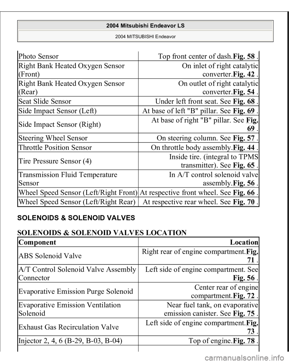
SOLENOIDS & SOLENOID VALVES SOLENOIDS & SOLENOID VALVES LOCATION Photo Sensor
Top front center of dash.Fig. 58
.
Right Bank Heated Oxygen Sensor
(Front)
On inlet of right catalytic
converter.Fig. 42
.
Right Bank Heated Oxygen Sensor
(Rear)
On outlet of right catalytic
converter.Fig. 54
.
Seat Slide Sensor
Under left front seat. See Fig. 68
.
Side Impact Sensor (Left)
At base of left "B" pillar. See Fig. 69
.
Side Impact Sensor (Right)
At base of right "B" pillar. See Fig.
69 .
Steering Wheel Sensor
On steering column. See Fig. 57
.
Throttle Position Sensor
On throttle body assembly.Fig. 44
.
Tire Pressure Sensor (4)
Inside tire. (integral to TPMS
transmitter). See Fig. 65
.
Transmission Fluid Temperature
Sensor
In A/T control solenoid valve
assembly.Fig. 56
.
Wheel Speed Sensor (Left/Right Front)
At respective front wheel. See Fig. 66
.
Wheel Speed Sensor (Left/Right Rear)
At respective rear wheel. See Fig. 70
.
Component
Location
ABS Solenoid Valve
Right rear of engine compartment.Fig.
71 .
A/T Control Solenoid Valve Assembly
Connector
Left side of engine compartment. See
Fig. 56
.
Evaporative Emission Purge Solenoid
Center rear of engine
compartment.Fig. 72
.
Evaporative Emission Ventilation
Solenoid
Near fuel tank, on evaporative
emission canister. See Fig. 75
.
Exhaust Gas Recirculation Valve
Left side of engine compartment.Fig.
73 .
Injector 2, 4, 6 (B-29, B-03, B-04)
Top of engine.Fig. 78
.
2004 Mitsubishi Endeavor LS
2004 MITSUBISHI Endeavor
Page 1863 of 3870
Fig. 11: Measuring Wheel Bearing Axial Play
Courtesy of MITSUBISHI MOTOR SALES OF AMERICA.
DRIVE SHAFT ASSEMBLY REMOVAL AND INSTALLATION
CAUTION:
For vehicles with ABS, do not strike the ABS
rotors installed to the BJ outer race of drive shaft
against other parts when removing or installing
the drive shaft. Otherwise the ABS rotors will be
damaged. For vehicles with ABS, be careful not to strike the
pole piece at the tip of the front ABS sensor with
tools during servicing work.
2004 Mitsubishi Endeavor LS
2004 DRIVELINE/AXLES Front Axle Hub & Axle Shafts - Endeavor
Page 1945 of 3870
Fig. 4: Special Tools (2 Of 2)
Courtesy of MITSUBISHI MOTOR SALES OF AMERICA.
ON-VEHICLE SERVICE FRONT WHEEL ALIGNMENT CHECK AND ADJUSTMENT Measure wheel alignment with alignment equipment on a level surface. The front
sus
pension, steerin
g system, wheels, and tires should be serviced to normal
CAUTION: On vehicles with ASC, if the wheel alignment is
adjusted, always carry out steering wheel sensor
calibration (STEERING WHEEL SENSOR
CALIBRATION
). This is necessary because the
TCL/ASC-ECU should update the steering neutral
point.
2004 Mitsubishi Endeavor LS 2004 SUSPENSION Front - Endeavor
Page 1947 of 3870

Tightening torque: 52 +/- 2 N.m (38 +
/-2 f
t-lb)
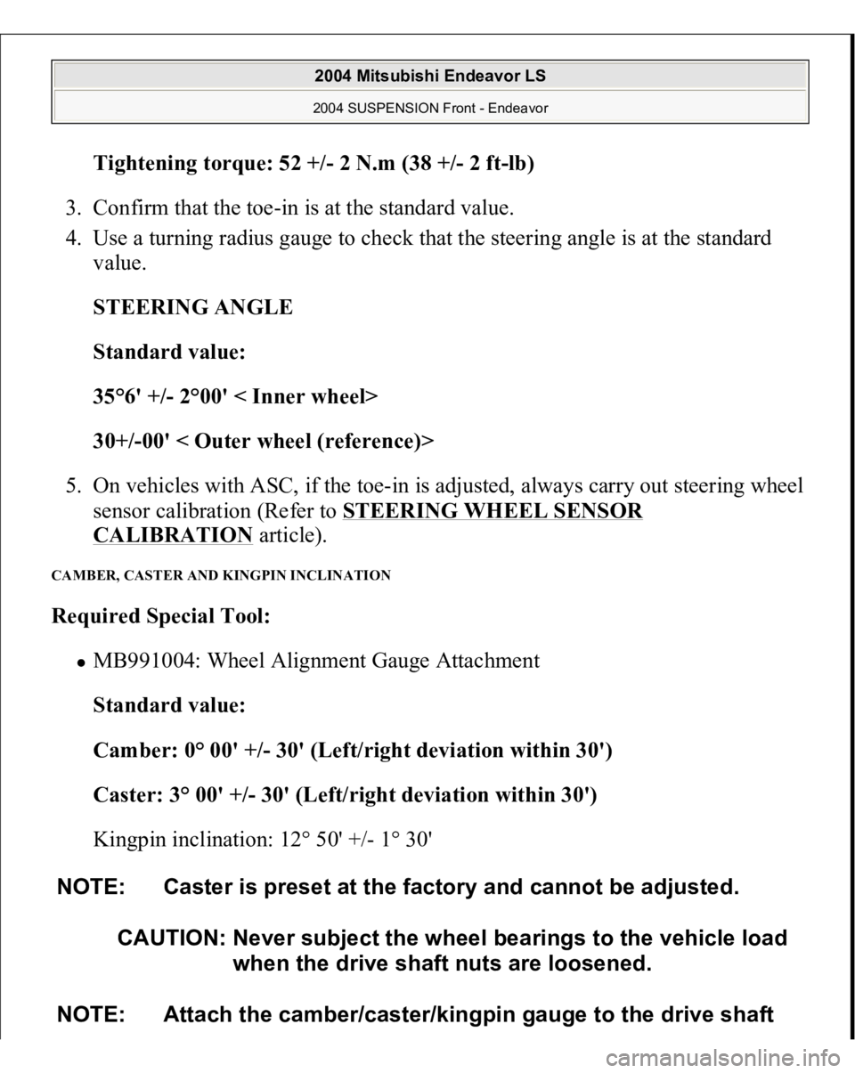
3. Confirm that the toe-in is at the standard value.
4. Use a turning radius gauge to check that the steering angle is at the standard
value.
STEERING ANGLE
Standard value:
35°6' +/- 2°00' < Inner wheel>
30+/-00' < Outer wheel (reference)>
5. On vehicles with ASC, if the toe-in is adjusted, always carry out steering wheel
sensor calibration (Refer to STEERING WHEEL SENSOR
CALIBRATION
article).
CAMBER, CASTER AND KINGPIN INCLINATION Required Special Tool:
MB991004: Wheel Alignment Gauge Attachment
Standard value:
Camber: 0° 00' +/- 30' (Left/right deviation within 30')
Caster: 3° 00' +/- 30' (Left/right deviation within 30')
Kingpin inclination: 12° 50' +/- 1° 30'
NOTE: Caster is preset at the factory and cannot be adjusted.
CAUTION: Never subject the wheel bearings to the vehicle load
when the drive shaft nuts are loosened.
NOTE: Attach the camber/caster/kingpin gauge to the drive shaft
2004 Mitsubishi Endeavor LS 2004 SUSPENSION Front - Endeavor
Page 2843 of 3870
wheel circumference and check the play.
Standard value (steering wheel play with the engine stopped): 10 mm (0.4
inch) or less
5. If the play exceeds the standard value, remove the steering gear (Refer to
POWER STEERING GEAR BOX AND LINKAGE
.) and check the total
pinion torque (Refer to STEERING GEAR TOTAL PINION TORQUE
CHECK
.).
STEERING ANGLE CHECK 1. Place the front wheel on a turnin
g radius
gauge an
d measure the steerin
g an
gle.
CAUTION: On vehicles with ASC, if the steering angle is
adjusted, always carry out steering wheel sensor
calibration (Refer to STEERING WHEEL SENSOR
CALIBRATION
). This is necessary because the
TCL/ASC-ECU should update the steering neutral
point.
2004 Mitsubishi Endeavor LS
2004 STEERING Power Steering - Endeavor
Page 2846 of 3870
Fig. 16: Adjusting Toe
Courtesy of MITSUBISHI MOTOR SALES OF AMERICA.
3. Recheck the steering angle.
4. On vehicles with ASC, if the steering angle is adjusted, always carry out
steering wheel sensor calibration (Refer to STEERING WHEEL SENSOR
CALIBRATION
).
TIE ROD END BALL JOINT BREAKAWAY TORQUE CHECK Required Special Tools:
MB990326: Preload Socket MB991897: Ball Joint Remover
CAUTION:
Do not remove the nut from ball
joint. Loosen it
2004 Mitsubishi Endeavor LS
2004 STEERING Power Steering - Endeavor
Page 2870 of 3870

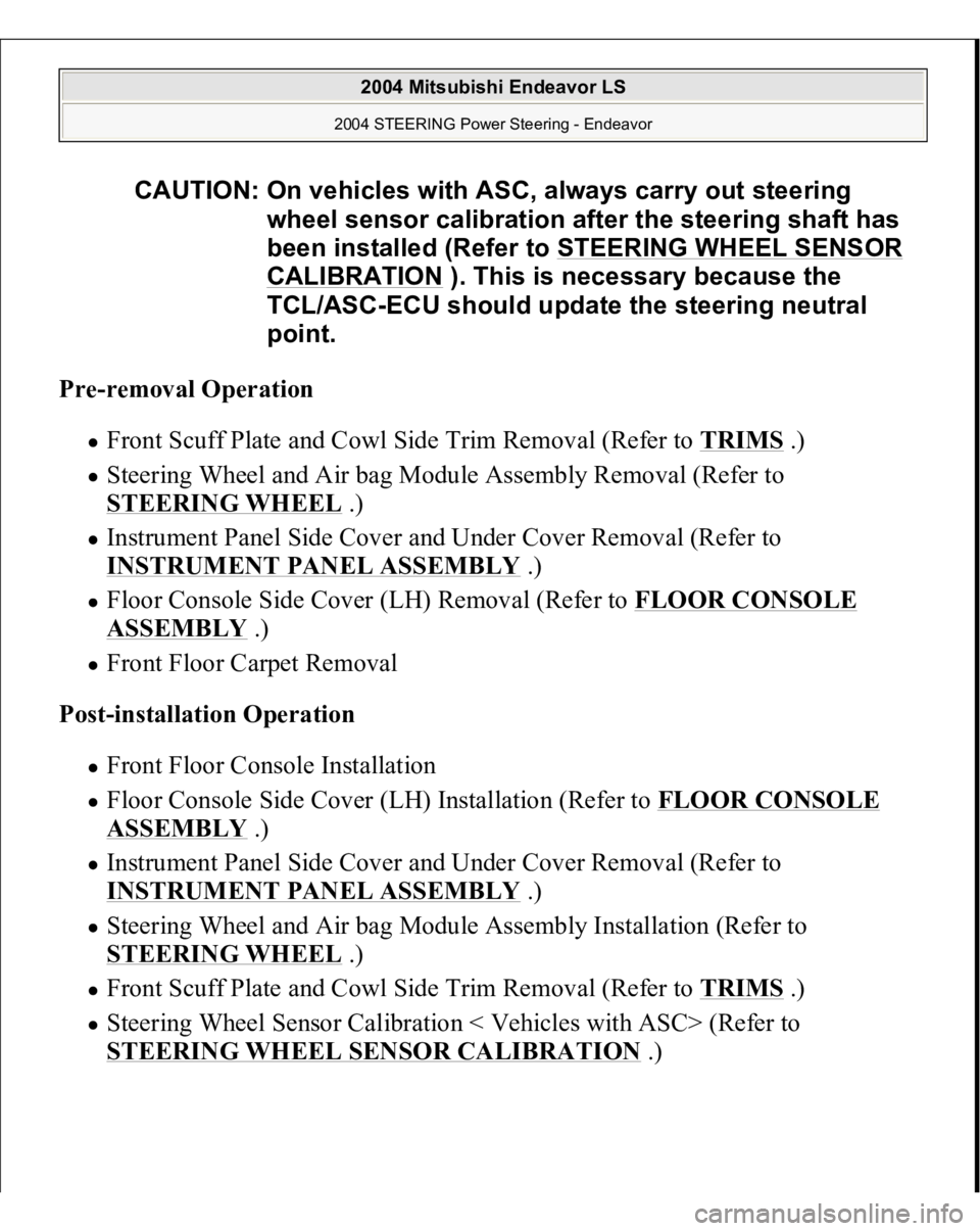
Pre-removal Operation
Front Scuff Plate and Cowl Side Trim Removal (Refer to TRIMS
.)
Steering Wheel and Air bag Module Assembly Removal (Refer to
STEERING WHEEL
.)
Instrument Panel Side Cover and Under Cover Removal (Refer to
INSTRUMENT PANEL ASSEMBLY
.)
Floor Console Side Cover (LH) Removal (Refer to FLOOR CONSOLE ASSEMBLY
.)
Front Floor Carpet Removal
Post-installation Operation Front Floor Console Installation Floor Console Side Cover (LH) Installation (Refer to FLOOR CONSOLE ASSEMBLY
.)
Instrument Panel Side Cover and Under Cover Removal (Refer to
INSTRUMENT PANEL ASSEMBLY
.)
Steering Wheel and Air bag Module Assembly Installation (Refer to
STEERING WHEEL
.)
Front Scuff Plate and Cowl Side Trim Removal (Refer to TRIMS
.)
Steering Wheel Sensor Calibration < Vehicles with ASC> (Refer to
STEERING WHEEL SENSOR CALIBRATION
.)
CAUTION: On vehicles with ASC, always carry out steering
wheel sensor calibration after the steering shaft has
been installed (Refer to STEERING WHEEL SENSOR
CALIBRATION
). This is necessary because the
TCL/ASC-ECU should update the steering neutral
point.
2004 Mitsubishi Endeavor LS
2004 STEERING Power Steering - Endeavor
Page 2876 of 3870
Fig. 34: Checking Tilt Lever Position
Courtesy of MITSUBISHI MOTOR SALES OF AMERICA.
INSTALLATION SERVICE POINT >>B<< STEERING WHEEL SENSOR < VEHICLES WITH ASC>, CLOCK
SPRING AND COLUMN SWITCH ASSEMBLY INSTALLATION 1. Align the mating marks of the clock spring.
WARNING:Ensure that the clock spring's mating marks are
properly aligned. If not, the steering wheel may not
rotate completely during a turn, or the flat cable in
the clock spring could be damaged, This would
prevent normal SRS operation and possibly cause
serious injury to the driver.
2004 Mitsubishi Endeavor LS
2004 STEERING Power Steering - Endeavor