Page 252 of 3870

Fig. 149: Identifying Output Voltage Grap
h
Courtesy of MITSUBISHI MOTOR SALES OF AMERICA.
Probable causes of low output voltage
ABS sensor pole piece-to-ABS rotor clearance too large Faulty ABS sensor
4. To observe the waveform with an oscilloscope:
Front Wheels: Shift into "D" range and drive the wheels. Rear Wheels: Turn the wheels manually at a constant speed
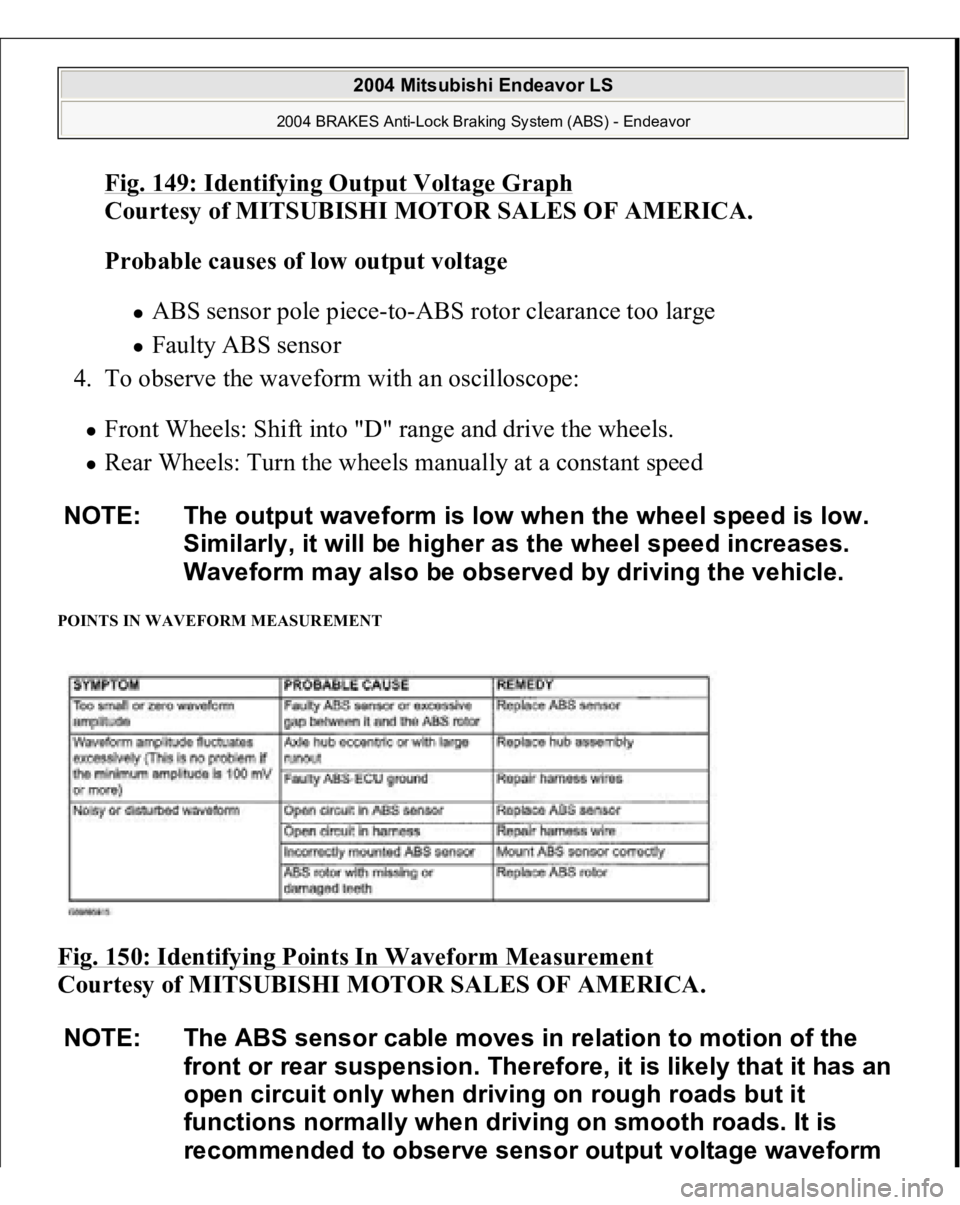
POINTS IN WAVEFORM MEASUREMENT Fig. 150: Identifying Points In Waveform Measurement
Courtesy of MITSUBISHI MOTOR SALES OF AMERICA. NOTE: The output waveform is low when the wheel speed is low.
Similarly, it will be higher as the wheel speed increases.
Waveform may also be observed by driving the vehicle.
NOTE: The ABS sensor cable moves in relation to motion of the
front or rear suspension. Therefore, it is likely that it has an
open circuit only when driving on rough roads but it
functions normally when driving on smooth roads. It is
recommended to observe sensor output voltage waveform
2004 Mitsubishi Endeavor LS
2004 BRAKES Anti-Lock Braking System (ABS) - Endeavor
Page 262 of 3870
Fig. 157: Identifying Brake Tube Connection
Courtesy of MITSUBISHI MOTOR SALES OF AMERICA.
WHEEL SPEED SENSOR REMOVAL AND INSTALLATION
2004 Mitsubishi Endeavor LS
2004 BRAKES Anti-Lock Braking System (ABS) - Endeavor
Page 263 of 3870
Fig. 158: Removing & Installing Wheel Speed Sensor
Courtesy of MITSUBISHI MOTOR SALES OF AMERICA.
Fig. 159: Wheel Speed Sensor Removal & Installation Legend
Courtesy of MITSUBISHI MOTOR SALES OF AMERICA.
2004 Mitsubishi Endeavor LS
2004 BRAKES Anti-Lock Braking System (ABS) - Endeavor
Page 266 of 3870
1. Check whether any metallic foreign material has adhered to the projection at
the speed sensor tip. Remove any foreign material. Also check whether the
pole piece is damaged. Replace it with a new one if it is damaged.
2. Measure the resistance between the ABS sensor terminals.
Standard value: 1.24 - 1.64 kohm
Fig. 161: Measuring Resistance Between ABS Sensor Terminals
Courtesy of MITSUBISHI MOTOR SALES OF AMERICA.
3. If the internal resistance of the ABS sensor is no
t within the standard value, NOTE: The projection can become magnetized due to the
magnet inside the ABS sensor, causing foreign material
to easily adhere to it. The projection may not be able to
correctly sense the wheel rotation speed if foreign
matter is on it or if it is damaged.
2004 Mitsubishi Endeavor LS
2004 BRAKES Anti-Lock Braking System (ABS) - Endeavor
Page 286 of 3870
Fig. 7: Identifying Front Impact Sensor (Dual
-stage Air Bag System)
Courtesy of MITSUBISHI MOTOR SALES OF AMERICA.
INSTRUMENT PANEL Removal & Installation 1. Before proceeding, see AIR BAG SAFETY PRECAUTIONS
. Turn ignition
off. Disable air bag system. See DISABLING & ACTIVATING AIR BAG
SYSTEM
.
2. Remove driver-side air bag module and steering wheel. See DRIVER
-SIDE
AIR BAG MODULE & CLOCKSPRING
. Remove front scuff plates.
Remove cowl side trim. Remove floor console assembl
y. See FLOOR
2004 Mitsubishi Endeavor Limited
2004 ACCESSORIES/SAFETY EQUIPMENT Mitsubishi - Air Bag Restraint Systems
Page 287 of 3870

CONSOLE ASSEMBL
Y . Remove left and right A-pillar trim panels.
Remove hood lock release handle.
3. Remove end panel. See Fig. 8
. Remove driver-side knee bolster. Remove fog
light switch. Remove steering column upper and lower covers. Remove
combination meter assembly. Remove center panel assembly. Remove air
vents. Remove radio panel. Remove AC-heater control assembly.
4. Remove hazard warning switch. Remove console meter hood. Remove multi-
center display unit. Remove audio components. Remove glove box assembly.
Remove left and right speaker covers. Remove speakers. Disconnect
clockspring and steering column switch connectors. Remove photo sensor and
photo sensor clamp.
5. Remove interior temperature sensor. Disconnect passenger-side air bag module
connector. Remove left and right center instrument panel brackets. Disconnect
remaining electrical connectors. Remove instrument panel nuts and bolts.
Remove instrument panel.
6. To install, reverse removal procedure. Tighten NEW steering wheel nut and
drive
r-side air ba
g module bolts to s
pecification. Activate air ba
g system.
2004 Mitsubishi Endeavor Limited
2004 ACCESSORIES/SAFETY EQUIPMENT Mitsubishi - Air Bag Restraint Systems
Page 299 of 3870

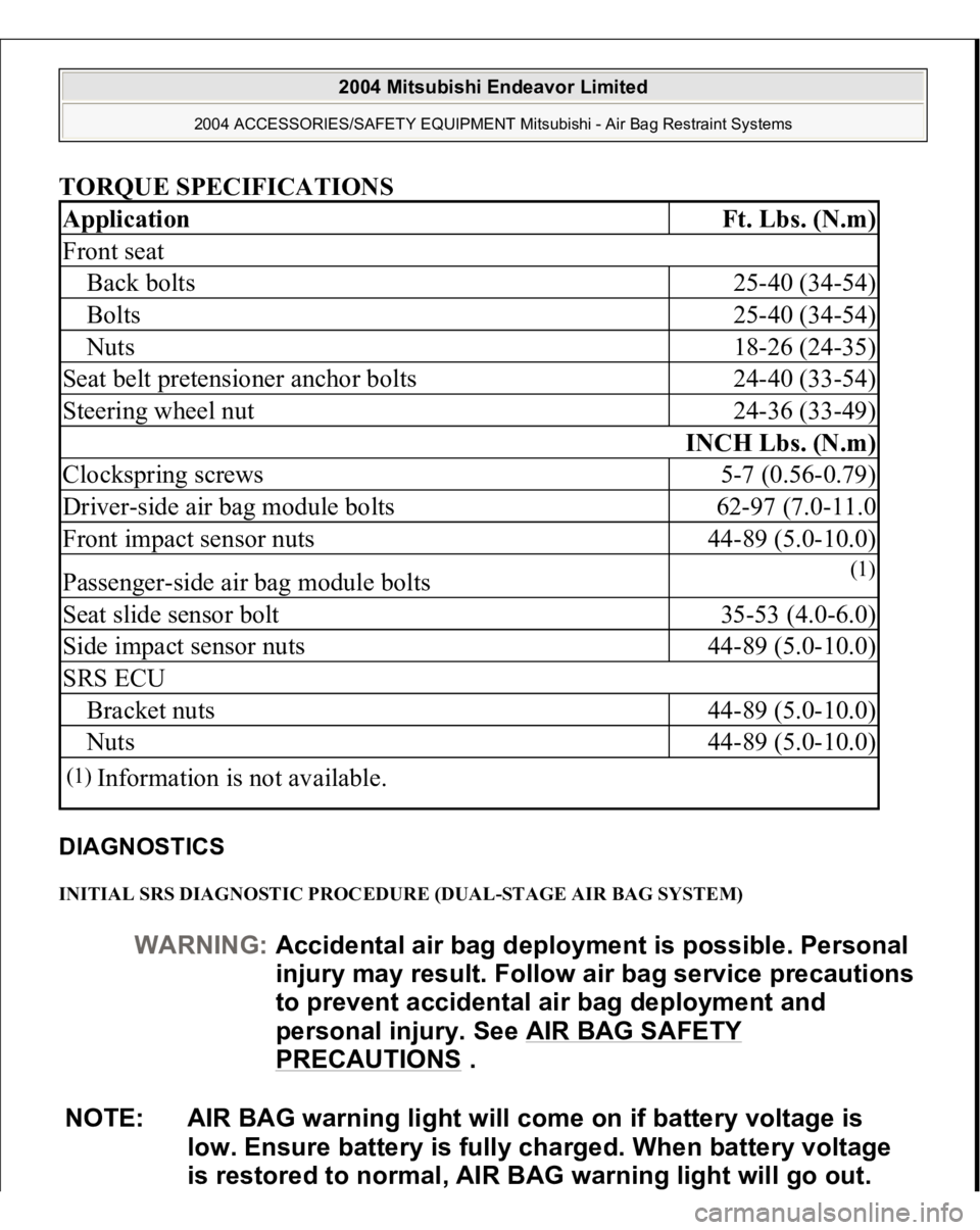
TORQUE SPECIFICATIONS DIAGNOSTICS INITIAL SRS DIAGNOSTIC PROCEDURE (DUAL-STAGE AIR BAG SYSTEM) Application
Ft. Lbs. (N.m)
Front seatBack bolts
25-40 (34-54)
Bolts
25-40 (34-54)
Nuts
18-26 (24-35)
Seat belt pretensioner anchor bolts
24-40 (33-54)
Steering wheel nut
24-36 (33-49)
INCH Lbs. (N.m)
Clockspring screws
5-7 (0.56-0.79)
Driver-side air bag module bolts
62-97 (7.0-11.0
Front impact sensor nuts
44-89 (5.0-10.0)
Passenger-side air bag module bolts
(1)
Seat slide sensor bolt
35-53 (4.0-6.0)
Side impact sensor nuts
44-89 (5.0-10.0)
SRS ECUBracket nuts
44-89 (5.0-10.0)
Nuts
44-89 (5.0-10.0)
(1)
Information is not available.
WARNING:Accidental air bag deployment is possible. Personal
in
jury ma
y result. Follow air ba
g service precautions
to prevent accidental air bag deployment and
personal injury. See AIR BAG SAFETY
PRECAUTIONS
.
NOTE: AIR BAG warning light will come on if battery voltage is
low. Ensure battery is fully charged. When battery voltage
is restored to normal, AIR BAG warning light will go out.
2004 Mitsubishi Endeavor Limited
2004 ACCESSORIES/SAFETY EQUIPMENT Mitsubishi - Air Bag Restraint Systems
Page 744 of 3870
The brake fluid level sensor is in good condition if there is no continuity when the
float surface is above "MIN" and if there is continuity when the float surface is
below "MIN".
Fig. 28: Checking Brake Fluid Level Sensor
Courtesy of MITSUBISHI MOTOR SALES OF AMERICA.
DISC BRAKE PAD CHECK AND REPLACEMENT NOTE: The brake pads (LH wheel) have indicators that contact the
brake disc when the brake pad thickness becomes 2 mm
(0.08 inch), and emit a squealing sound to warn the driver.
2004 Mitsubishi Endeavor LS
2004 BRAKES Basic Brake System - Endeavor