Page 2002 of 3870
INTRODUCTION TO HEATER, AIR CONDITIONING AND VENTILATION DIAGNOSISAir is drawn into the heater assembly from either the outside, or from the inside of
the passenger cabin if DEFROST, maximum cooling or RECIRCULATION are
selected. The air is then forced through the evaporator where heat is removed,
cooling and de-humidifying the air. Depending on the temperature selected, a
portion of this air is then forced through the heater core to achieve the selected
discharge temperature.
If the system does not cool properly, look for a problem with the refrigerant, blower
or air distribution systems. If the system does not heat properly, look for a problem
with the coolant, blower or air distribution systems. In either case all system fuses,
circuit breaker and relays should be checked. HEATER, AIR CONDITIONING AND VENTILATION DIAGNOSTIC TROUBLESHOOTING
STRATEGY Use these steps to plan your diagnostic strategy. If you follow them carefully, you
will be sure that you have exhausted most of the possible ways to find a heater, air
conditioning and ventilation fault.
1. Gather information from the customer.
2. Verify that the condition described by the customer exists.
3. Find the malfunction by following
SYMPTOM CHART
4. Verify that the malfunction is eliminated.
DIAGNOSTIC FUNCTION HOW TO CONNECT THE SCAN TOOL (MUT-III) REQUIRED SPECIAL TOOL:
MB991958: Scan Tool (MUT-III Sub Assembly)
MB991824: Vehicle Communication Interface (V.C.I.) MB991827: MUT-III USB Cable MB991910: MUT-III Main Harness A (Vehicles with CAN
communication system)
2004 Mitsubishi Endeavor LS
2004 HVAC Heater Air Conditioning, Ventilation - Endeavor
Page 2422 of 3870
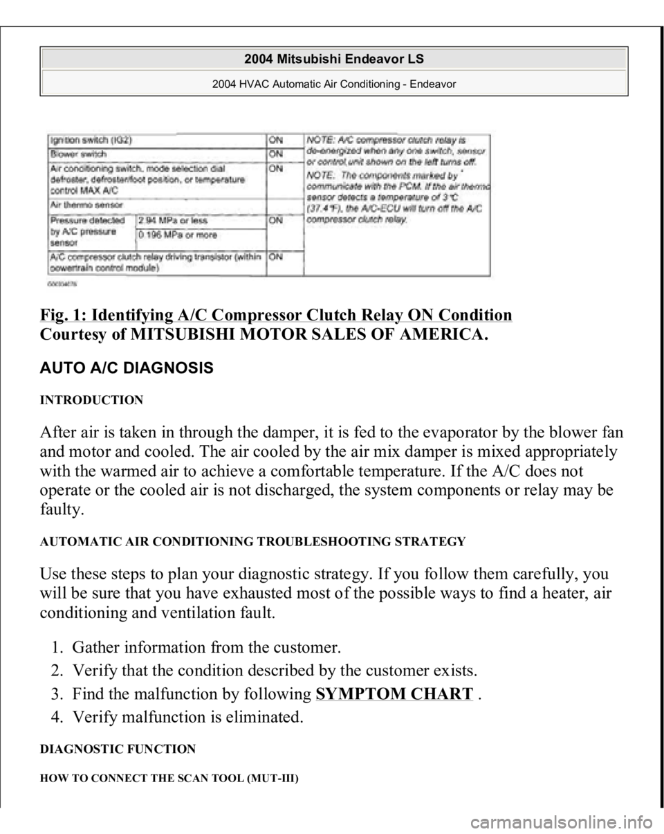
Fig. 1: Identifying A/C Compressor Clutch Relay ON Condition
Courtesy of MITSUBISHI MOTOR SALES OF AMERICA.
AUTO A/C DIAGNOSIS INTRODUCTION After air is taken in through the damper, it is fed to the evaporator by the blower fan
and motor and cooled. The air cooled by the air mix damper is mixed appropriately
with the warmed air to achieve a comfortable temperature. If the A/C does not
operate or the cooled air is not discharged, the system components or relay may be
faulty. AUTOMATIC AIR CONDITIONING TROUBLESHOOTING STRATEGY Use these steps to plan your diagnostic strategy. If you follow them carefully, you
will be sure that you have exhausted most of the possible ways to find a heater, air
conditioning and ventilation fault.
1. Gather information from the customer.
2. Verify that the condition described by the customer exists.
3. Find the malfunction by following
SYMPTOM CHART
.
4. Verify malfunction is eliminated.
DIAGNOSTIC FUNCTION HOW TO CONNECT THE SCAN TOOL (MUT-III)
2004 Mitsubishi Endeavor LS
2004 HVAC Automatic Air Conditioning - Endeavor
Page 2522 of 3870
Courtesy of MITSUBISHI MOTOR SALES OF AMERICA
.
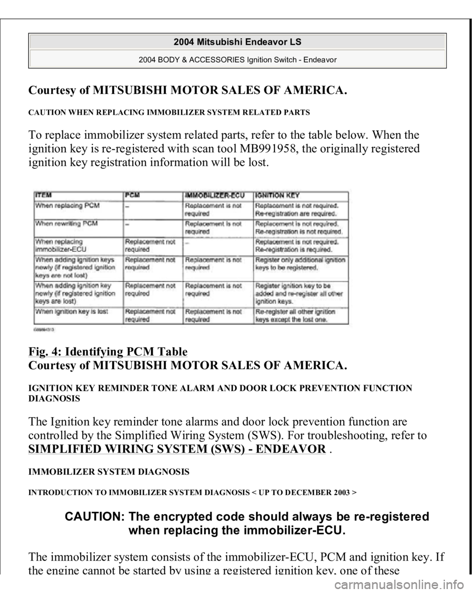
CAUTION WHEN REPLACING IMMOBILIZER SYSTEM RELATED PARTS To replace immobilizer system related parts, refer to the table below. When the
ignition key is re-registered with scan tool MB991958, the originally registered
ignition key registration information will be lost.
Fig. 4: Identifying PCM Table
Courtesy of MITSUBISHI MOTOR SALES OF AMERICA.
IGNITION KEY REMINDER TONE ALARM AND DOOR LOCK PREVENTION FUNCTION
DIAGNOSIS The Ignition key reminder tone alarms and door lock prevention function are
controlled by the Simplified Wiring System (SWS). For troubleshooting, refer to
SIMPLIFIED WIRING SYSTEM (SWS)
- ENDEAVOR
.
IMMOBILIZER SYSTEM DIAGNOSIS INTRODUCTION TO IMMOBILIZER SYSTEM DIAGNOSIS < UP TO DECEMBER 2003 > The immobilizer system consists of the immobilizer-ECU, PCM and ignition key. I
f
the engine cannot be sta
rted
by using a registe
red ignition k
ey,
one of these
CAUTION: The encrypted code should always be re-registered
when replacing the immobilizer-ECU.
2004 Mitsubishi Endeavor LS
2004 BODY & ACCESSORIES Ignition Switch - Endeavor
Page 2523 of 3870
components may be defective. If the immobilizer system has immobilized the
engine, MFI system DTC P0513 will be output. In this case, observe the
immobilizer system troubleshooting. INTRODUCTION TO IMMOBILIZER SYSTEM DIAGNOSIS < FROM TO JANUARY 2004 > The immobilizer system consists of the immobilizer-ECU, PCM, ignition key and
ignition key ring antenna. If the engine cannot be started by using a registered
ignition key, one of these components may be defective. If the immobilizer system
has immobilized the engine, MFI system DTC P0513 will be output. In this case,
observe the immobilizer system troubleshooting. IMMOBILIZER SYSTEM DIAGNOSTIC TROUBLESHOOTING STRATEGY Use the following steps to plan your diagnostic strategy.
1. Gather information about the problem from the customer.
2. Verify that the condition as described by the customer exists.
3. Check the vehicle for any immobilizer system DTCs.
4. If you cannot verify the condition and there are no immobilizer system DTCs,
the malfunction is intermittent. Refer to HOW TO COPE WITH
INTERMITTENT MALFUNCTIONS
.
5. If you can verify the condition but there are no immobilizer system DTCs, or
the system cannot communicate with scan tool MB991958, refer to
SYMPTOM CHART AND FIND THE FAULT
.
6. If there is an immobilizer system DTC, record the DTC, then erase it from the
memory using scan tool MB991958.
7. Recreate the immobilizer system DTC set conditions to see if the same
immobilizer system DTC will resets.
1. If the same immobilizer system DTC resets, perform the appropriate
diagnostic procedure. Refer to DIAGNOSTIC TROUBLE CODE
CHART
.
2. If the same immobilizer s
ystem DTC does not reset
, the malfunction is
CAUTION: The encrypted code should always be re-registered
when replacing the immobilizer-ECU.
2004 Mitsubishi Endeavor LS
2004 BODY & ACCESSORIES Ignition Switch - Endeavor
Page 2706 of 3870
2004 ENGINE
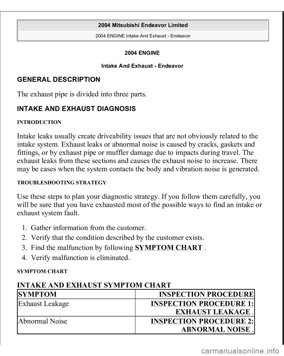
Intake And Exhaust - Endeavor
GENERAL DESCRIPTION The exhaust pipe is divided into three parts. INTAKE AND EXHAUST DIAGNOSIS INTRODUCTION Intake leaks usually create driveability issues that are not obviously related to the
intake system. Exhaust leaks or abnormal noise is caused by cracks, gaskets and
fittings, or by exhaust pipe or muffler damage due to impacts during travel. The
exhaust leaks from these sections and causes the exhaust noise to increase. There
may be cases when the system contacts the body and vibration noise is generated. TROUBLESHOOTING STRATEGY Use these steps to plan your diagnostic strategy. If you follow them carefully, you
will be sure that you have exhausted most of the possible ways to find an intake or
exhaust system fault.
1. Gather information from the customer.
2. Verify that the condition described by the customer exists.
3. Find the malfunction by following SYMPTOM CHART
.
4. Verify malfunction is eliminated.
SYMPTOM CHART INTAKE AND EXHAUST SYMPTOM CHART SYMPTOM
INSPECTION PROCEDURE
Exhaust Leakage
INSPECTION PROCEDURE 1:
EXHAUST LEAKAGE
.
Abnormal Noise
INSPECTION PROCEDURE 2:
ABNORMAL NOISE
.
2004 Mitsubishi Endeavor Limited 2004 ENGINE Intake And Exhaust - Endeavor
2004 Mitsubishi Endeavor Limited 2004 ENGINE Intake And Exhaust - Endeavor
Page 2787 of 3870
Fig. 1: Identifying Parking Brakes Assembly
Courtesy of MITSUBISHI MOTOR SALES OF AMERICA.
PARKING BRAKE DIAGNOSIS INTRODUCTION If the parking brake is faulty, parking brake effort will become insufficient. The
cause may be a malfunction of parking brake parts or the parking brake pedal being
out of ad
justment.
2004 Mitsubishi Endeavor LS 2004 BRAKES Parking Brakes - Endeavor
Page 2816 of 3870
INTRODUCTION TO POWER STEERING DIAGNOSISHydraulic power steering is used for all vehicles. Faults in the power steering can
include excessive play of the steering wheel, difficult steering wheel operation,
noise, vibration, and oil leaks, etc. Possible causes of these faults can include
defects in the gear box, oil pump or steering linkage. POWER STEERING DIAGNOSIS TROUBLESHOOTING STRATEGY Use these steps to plan your diagnostic strategy. If you follow them carefully, you
will be sure that you have exhausted most of the possible ways to find a power
steering fault.
1. Gather information from the customer.
2. Verify that the condition described by the customer exists.
3. Find the malfunction by following the Symptom Chart.
4. Verify malfunction is eliminated. SYMPTOM CHART
2004 Mitsubishi Endeavor LS
2004 STEERING Power Steering - Endeavor
Page 2926 of 3870
Fig. 1: Identifying Rear Axle Components
Courtesy of MITSUBISHI MOTOR SALES OF AMERICA.
REAR AXLE DIAGNOSIS INTRODUCTION Noise from the drive shaft or differential may be caused by defects in the
components. TROUBLESHOOTING STRATEGY Use these steps to plan your diagnostic strategy. If you follow them carefully, you
will be sure that you have exhausted most of the possible ways to find a rear axle
fault.
1. Gather information from the customer.
2004 Mitsubishi Endeavor LS
2004 SUSPENSION Rear Axle < AWD > - Endeavor