2004 MITSUBISHI ENDEAVOR can bus
[x] Cancel search: can busPage 388 of 3870
SRS ELECTRONIC CONTROL UNIT (SRS ECU)
under REMOVAL &
INSTALLATION. If DTC B1464 is not retrieved, an intermittent condition
may exist.
DTC B1465: BELT PRETENSIONER (RH) IGNITION DRIVE CIRCUIT SHORT DETECTED 1. Connect scan tool to Data Link Connector (DLC). See INITIAL SRS
DIAGNOSTIC PROCEDURE
under DIAGNOSTICS. If scan tool is able to
diagnose CAN bus lines and CAN bus lines are satisfactory, go to next step. If
scan tool cannot diagnose CAN bus lines, repair CAN bus lines. Go to next
step.
2. Erase, then retrieve DTCs. If DTC B1465 is retrieved, replace SRS ECU. See
SRS ELECTRONIC CONTROL UNIT (SRS ECU)
under REMOVAL &
INSTALLATION. If DTC B1465 is not retrieved, an intermittent condition
may exist.
DTC B1466: ANALOG G SENSOR MALFUNCTION 1. Connect scan tool to Data Link Connector (DLC). See INITIAL SRS
DIAGNOSTIC PROCEDURE
under DIAGNOSTICS. If scan tool is able to
diagnose CAN bus lines and CAN bus lines are satisfactory, go to next step. If
scan tool cannot diagnose CAN bus lines, repair CAN bus lines. Go to next
step.
2. Erase, then retrieve DTCs. If DTC B1466 is retrieved, replace SRS ECU. See
SRS ELECTRONIC CONTROL UNIT (SRS ECU)
under REMOVAL &
INSTALLATION. If DTC B1466 is not retrieved, an intermittent condition
may exist.
DTC B1467: SAFING G SENSOR OPEN CIRCUIT (FRONTAL IMPACT) 1. Connect scan tool to Data Link Connector (DLC). See INITIAL SRS
DIAGNOSTIC PROCEDURE
under DIAGNOSTICS. If scan tool is able to
diagnose CAN bus lines and CAN bus lines are satisfactory, go to next step. If
scan tool cannot diagnose CAN bus lines, repair CAN bus lines. Go to next
step.
2. Erase, then retrieve DTCs. If DTC B1467 is retrieved, replace SRS ECU. See
SRS ELECTRONIC CONTROL UNIT (SRS ECU)
under REMOVAL &
2004 Mitsubishi Endeavor Limited
2004 ACCESSORIES/SAFETY EQUIPMENT Mitsubishi - Air Bag Restraint Systems
Page 389 of 3870
INSTALLATION. If DTC B1467 is not retrieved, an intermittent condition
may exist.
DTC B1468: SAFING G SENSOR SHORT CIRCUIT (FRONTAL IMPACT) 1. Connect scan tool to Data Link Connector (DLC). See INITIAL SRS
DIAGNOSTIC PROCEDURE
under DIAGNOSTICS. If scan tool is able to
diagnose CAN bus lines and CAN bus lines are satisfactory, go to next step. If
scan tool cannot diagnose CAN bus lines, repair CAN bus lines. Go to next
step.
2. Erase, then retrieve DTCs. If DTC B1468 is retrieved, replace SRS ECU. See
SRS ELECTRONIC CONTROL UNIT (SRS ECU)
under REMOVAL &
INSTALLATION. If DTC B1468 is not retrieved, an intermittent condition
may exist.
DTC B1469: SAFING G SENSOR MALFUNCTION (SIDE IMPACT) 1. Connect scan tool to Data Link Connector (DLC). See INITIAL SRS
DIAGNOSTIC PROCEDURE
under DIAGNOSTICS. If scan tool is able to
diagnose CAN bus lines and CAN bus lines are satisfactory, go to next step. If
scan tool cannot diagnose CAN bus lines, repair CAN bus lines. Go to next
step.
2. Erase, then retrieve DTCs. If DTC B1469 is retrieved, replace SRS ECU. See
SRS ELECTRONIC CONTROL UNIT (SRS ECU)
under REMOVAL &
INSTALLATION. If DTC B1469 is not retrieved, an intermittent condition
may exist.
DTC B1470: SEAT BELT PRETENSIONER (LH) SHORT CIRCUIT 1. Connect scan tool to Data Link Connector (DLC). See INITIAL SRS
DIAGNOSTIC PROCEDURE
under DIAGNOSTICS. If scan tool is able to
diagnose CAN bus lines and CAN bus lines are satisfactory, go to next step. If
scan tool cannot diagnose CAN bus lines, repair CAN bus lines. Go to next
step.
2. Erase, then retrieve DTCs. Turn ignition off. If DTC B1470 is retrieved, go to
next step. If DTC B1470 is not retrieved, an intermittent condition may exist.
3. Turn ignition on. If DTC B1519 is retrieved by scan tool, go to next step. I
f
2004 Mitsubishi Endeavor Limited
2004 ACCESSORIES/SAFETY EQUIPMENT Mitsubishi - Air Bag Restraint Systems
Page 391 of 3870
diagnose CAN bus lines and CAN bus lines are satisfactory, go to next step. If
scan tool cannot diagnose CAN bus lines, repair CAN bus lines. Go to next
step.
2. Erase, then retrieve DTCs. Turn ignition off. If DTC B1471 is retrieved, go to
next step. If DTC B1471 is not retrieved, an intermittent condition may exist.
3. Disconnect negative battery cable. Disconnect driver seat belt pretensioner
connector D-24. See SEAT BELT PRETENSIONER
under REMOVAL &
INSTALLATION. See Fig. 30
. Connect Load Resistor (MB991865) to Load
Resistor Adapter (MB991844). Connect load resistor adapter to driver seat belt
pretensioner connector D-24. Connect negative battery cable. Erase, then
retrieve DTCs. If DTC B1471 is retrieved, go to next step. If DTC B1471 is
not retrieved, replace driver seat belt pretensioner connector. Go to step 6 .
4. Disconnect negative battery cable. Leaving load resistor adapter connected to
connector D-24, remove load resistor. Disconnect SRS ECU connector C-40.
Release SRS ECU connector shorting bar using a cable tie. Measure resistance
of Red/Yellow wire between SRS ECU C-40, connector terminal No. 8 and
driver seat belt pretensioner connector D-24, terminal No. 2. See Fig. 33
&
Fig. 38
. Measure resistance of Red/Blue wire between SRS ECU connector C-
40, terminal No. 7 and driver seat belt pretensioner connector D-24, terminal
No. 1. If resistance is less than 2 ohms in each wire, reconnect SRS
components. Erase, then retrieve DTCs. If DTC B1471 is retrieved, replace
SRS ECU. Go to step 6 . If resistance is more than 2 ohms in either wire, go to
next step.
5. Replace wire harness between SRS ECU and driver seat belt pretensioner. Go
to next step.
6. Reconnect all SRS components. Activate air bag system. Using scan tool,
retrieve DTCs. If DTC B1471 is retrieved, go to step 1 . If DTC B1471 is not
retrieved, system is normal at this time.
DTC B1472: SEAT BELT PRETENSIONER (LH) SHORT TO VOLTAGE 1. Connect scan tool to Data Link Connector (DLC). See INITIAL SRS
DIAGNOSTIC PROCEDURE
under DIAGNOSTICS. If scan tool is able to
diagnose CAN bus lines and CAN bus lines are satisfactory, go to next step. If
scan tool cannot dia
gnose CAN bus lines, re
pair CAN bus lines. Go to next
2004 Mitsubishi Endeavor Limited
2004 ACCESSORIES/SAFETY EQUIPMENT Mitsubishi - Air Bag Restraint Systems
Page 392 of 3870
step.
2. Erase, then retrieve DTCs. Turn ignition off. If DTC B1472 is retrieved, go to
next step. If DTC B1472 is not retrieved, an intermittent condition may exist.
3. Disconnect negative battery cable. Disconnect driver seat belt pretensioner
connector D-24. See SEAT BELT PRETENSIONER
under REMOVAL &
INSTALLATION. See Fig. 30
. Connect Load Resistor (MB991865) to Load
Resistor Adapter (MB991844). Connect load resistor adapter to driver seat belt
pretensioner connector D-24. Connect negative battery cable. Erase, then
retrieve DTCs. If DTC B1472 is retrieved, go to next step. If DTC B1472 is
not retrieved, replace driver seat belt pretensioner connector. Go to step 6 .
4. Remove load resistor and load resistor adapter from connector D-24.
Disconnect SRS ECU connector C-40 See SRS ELECTRONIC CONTROL
UNIT (SRS ECU)
under REMOVAL & INSTALLATION. Release SRS ECU
connector shorting bar using a cable tie. Measure voltage between ground and
SRS ECU connector C-40, connector terminal No. 8 (Red/Yellow wire). See
Fig. 33
. Measure voltage between ground and SRS ECU connector C-40,
terminal No. 7 (Red/Blue wire). If zero volt is measured at each terminal,
reconnect SRS components. Erase, then retrieve DTCs. If DTC B1472 is
retrieved, replace SRS ECU. Go to step 6 . If voltage is measured at either
terminal, go to next step.
5. Replace wire harness between SRS ECU and driver seat belt pretensioner. Go
to next step.
6. Reconnect all SRS components. Activate air bag system. Using scan tool,
retrieve DTCs. If DTC B1472 is retrieved, go to step 1 . If DTC B1472 is not
retrieved, system is normal at this time.
DTC B1473: SEAT BELT PRETENSIONER (LH) CIRCUIT SHORT TO GROUND 1. Connect scan tool to Data Link Connector (DLC). See INITIAL SRS
DIAGNOSTIC PROCEDURE
under DIAGNOSTICS. If scan tool is able to
diagnose CAN bus lines and CAN bus lines are satisfactory, go to next step. If
scan tool cannot diagnose CAN bus lines, repair CAN bus lines. Go to next
step.
2. Erase, then retrieve DTCs. Turn ignition off. If DTC B1473 is retrieved, go to
next ste
p. If DTC B1473 is not retrieved, an intermittent condition ma
y exist.
2004 Mitsubishi Endeavor Limited
2004 ACCESSORIES/SAFETY EQUIPMENT Mitsubishi - Air Bag Restraint Systems
Page 393 of 3870
3. Disconnect negative battery cable. Disconnect driver seat belt pretensioner
connector D-24. See SEAT BELT PRETENSIONER
under REMOVAL &
INSTALLATION. See Fig. 30
. Connect Load Resistor (MB991865) to Load
Resistor Adapter (MB991844). Connect load resistor adapter to driver seat belt
pretensioner connector D-24. Connect negative battery cable. Erase, then
retrieve DTCs. If DTC B1473 is retrieved, go to next step. If DTC B1473 is
not retrieved, replace driver seat belt pretensioner. Go to step 6 .
4. Disconnect negative battery cable. Remove load resistor and load resistor
adapter from connector D-24. Disconnect SRS ECU connector C-40. See SRS
ELECTRONIC CONTROL UNIT (SRS ECU)
under REMOVAL &
INSTALLATION. Release SRS ECU connector shorting bar using a cable tie.
Measure resistance between ground and SRS ECU connector C-40, terminal
No. 8 (Red/Yellow wire). See Fig. 33
. Measure resistance between ground and
SRS ECU connector C-40, terminal No. 7 (Red/Blue wire). If resistance is
infinite at both terminals, reconnect SRS components. Erase, then retrieve
DTCs. If DTC B1473 is retrieved, replace SRS ECU. Go to step 6 . If
resistance is not infinite at both terminals, go to next step.
5. Replace wire harness between SRS ECU and driver seat belt pretensioner. Go
to next step.
6. Reconnect all SRS components. Activate air bag system. Using scan tool,
retrieve DTCs. If DTC B1473 is retrieved, go to step 1 . If DTC B1473 is not
retrieved, system is normal at this time.
DTCB1474: SEAT BELT PRETENSIONER (LH) IGNITION DRIVE CIRCUIT SHORT DETECTED 1. Connect scan tool to Data Link Connector (DLC). See INITIAL SRS
DIAGNOSTIC PROCEDURE
under DIAGNOSTICS. If scan tool is able to
diagnose CAN bus lines and CAN bus lines are satisfactory, go to next step. If
scan tool cannot diagnose CAN bus lines, repair CAN bus lines. Go to next
step.
2. Erase, then retrieve DTCs. If DTC B1474 is retrieved, replace SRS ECU. See
SRS ELECTRONIC CONTROL UNIT (SRS ECU)
under REMOVAL &
INSTALLATION. If DTC B1474 is not retrieved, an intermittent condition
may exist.
DTCB1475: SEAT BELT PRETENSIONER
(LH
) IGNITION DRIVE CIRCUIT OPEN
2004 Mitsubishi Endeavor Limited
2004 ACCESSORIES/SAFETY EQUIPMENT Mitsubishi - Air Bag Restraint Systems
Page 394 of 3870
1. Connect scan tool to Data Link Connector (DLC). See INITIAL SRS
DIAGNOSTIC PROCEDURE
under DIAGNOSTICS. If scan tool is able to
diagnose CAN bus lines and CAN bus lines are satisfactory, go to next step. If
scan tool cannot diagnose CAN bus lines, repair CAN bus lines. Go to next
step.
2. Erase, then retrieve DTCs. If DTC B1475 is retrieved, replace SRS ECU. See
SRS ELECTRONIC CONTROL UNIT (SRS ECU)
under REMOVAL &
INSTALLATION. If DTC B1475 is not retrieved, an intermittent condition
may exist.
DTCB1476: POWER SUPPLY VOLTAGE DROPS ABNORMALLY 1. Connect scan tool to Data Link Connector (DLC). See INITIAL SRS
DIAGNOSTIC PROCEDURE
under DIAGNOSTICS. If scan tool is able to
diagnose CAN bus lines and CAN bus lines are satisfactory, go to next step. If
scan tool cannot diagnose CAN bus lines, repair CAN bus lines. Go to next
step.
2. Erase, then retrieve DTCs. Turn ignition off. If DTC B1476 is retrieved, go to
next step. If DTC B1476 is not retrieved, an intermittent condition may exist.
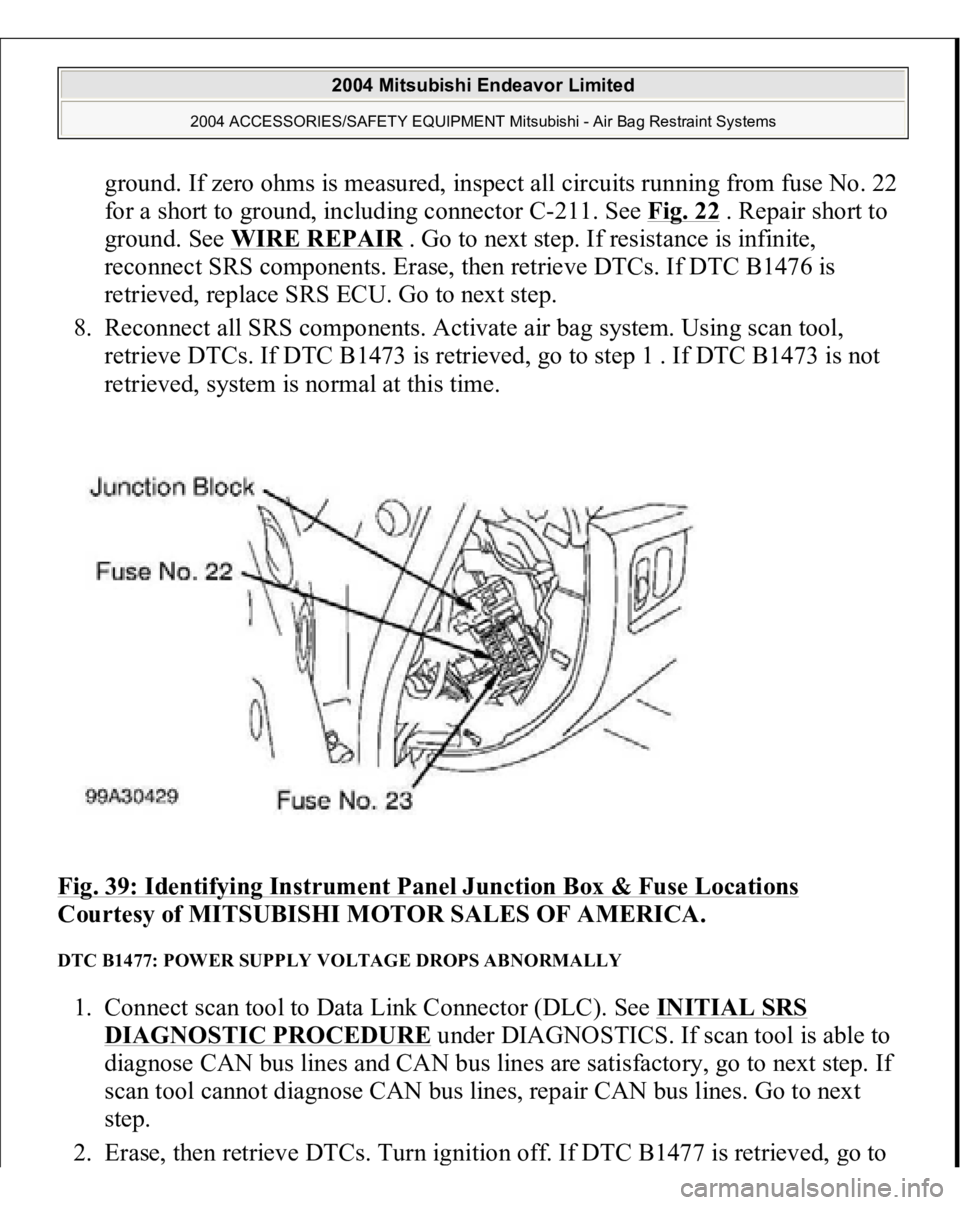
3. Remove fuse No. 22 from instrument panel junction block. See Fig. 39
. If fuse
is blown, go to step 6 . If fuse is not blown, go to next step.
4. Disconnect negative battery cable. Disconnect SRS ECU connector C-26. See
SRS ELECTRONIC CONTROL UNIT (SRS ECU)
under REMOVAL &
INSTALLATION. See Fig. 30
. Connect negative battery cable. Turn ignition
on. Measure voltage between ground and SRS ECU connector C-26, terminal
No. 23 (Black/White wire). If voltage is 9 volts or more, reconnect SRS
components. Erase, then retrieve DTCs. If DTC B1476 is retrieved, replace
SRS ECU. Go to step 8 . If DTC B1476 is not retrieved, go to next step.
5. Inspect Black/White wire between SRS ECU connector C-26, terminal No. 23
and ignition switch connector C-308, terminal No. 2. If wire is okay, go to step
8 . If wire is not okay, replace harness between SRS ECU and ignition switch.
Go to step 8 .
6. Replace fuse. Turn ignition on for one minute, then turn off. Inspect fuse. If
fuse is okay, go to step 8 . If fuse is not okay, go to next step.
7. Measure resistance between SRS ECU connector C-26
, terminal No. 23 and
2004 Mitsubishi Endeavor Limited
2004 ACCESSORIES/SAFETY EQUIPMENT Mitsubishi - Air Bag Restraint Systems
Page 395 of 3870
ground. If zero ohms is measured, inspect all circuits running from fuse No. 22
for a short to ground, including connector C-211. See Fig. 22
. Repair short to
ground. See WIRE REPAIR
. Go to next step. If resistance is infinite,
reconnect SRS components. Erase, then retrieve DTCs. If DTC B1476 is
retrieved, replace SRS ECU. Go to next step.
8. Reconnect all SRS components. Activate air bag system. Using scan tool,
retrieve DTCs. If DTC B1473 is retrieved, go to step 1 . If DTC B1473 is not
retrieved, system is normal at this time.
Fig. 39: Identifying Instrument Panel Junction Box & Fuse Locations
Courtesy of MITSUBISHI MOTOR SALES OF AMERICA.
DTC B1477: POWER SUPPLY VOLTAGE DROPS ABNORMALLY 1. Connect scan tool to Data Link Connector (DLC). See INITIAL SRS
DIAGNOSTIC PROCEDURE
under DIAGNOSTICS. If scan tool is able to
diagnose CAN bus lines and CAN bus lines are satisfactory, go to next step. If
scan tool cannot diagnose CAN bus lines, repair CAN bus lines. Go to next
step.
2. Erase, then retrieve DTCs. Turn ignition off. If DTC B1477 is retrieved,
go to
2004 Mitsubishi Endeavor Limited
2004 ACCESSORIES/SAFETY EQUIPMENT Mitsubishi - Air Bag Restraint Systems
Page 396 of 3870
next step. If DTC B1477 is not retrieved, an intermittent condition may exist.
3. Remove fuse No. 23 from instrument panel junction block. See Fig. 39
. If fuse
is blown, go to step 6 . If fuse is not blown, go to next step.
4. Disconnect negative battery cable. Disconnect SRS ECU connector C-26. See
SRS ELECTRONIC CONTROL UNIT (SRS ECU)
under REMOVAL &
INSTALLATION. See Fig. 30
. Connect negative battery cable. Turn ignition
on. Measure voltage between ground and SRS ECU connector C-26, terminal
No. 24 (Black/Yellow wire). If voltage is 9 volts or more, reconnect SRS
components. Erase, then retrieve DTCs. If DTC B1477 is retrieved, replace
SRS ECU. Go to step 8 . If DTC B1477 is not retrieved, go to next step.
5. Inspect Black/Yellow wire between SRS ECU connector C-26, terminal No. 24
and ignition switch connector C-308, terminal No. 2. See WIRING
DIAGRAMS
. If wire is okay, go to step 8 . If wire is not okay, replace
harness between SRS ECU and ignition switch. Go to step 8 .
6. Replace fuse. Turn ignition on for one minute, then turn off. Inspect fuse. If
fuse is okay, go to step 8 . If fuse is not okay, go to next step.
7. Measure resistance between SRS ECU connector terminal No. 24 and ground.
If zero ohms is measured, inspect all circuits running from fuse No. 23 for a
short to ground. including connector C-211. See Fig. 22
. Repair short to
ground. See WIRE REPAIR
. Go to next step. If continuity does not exist,
reconnect SRS components. Erase, then retrieve DTCs. If DTC B1477 is
retrieved, replace SRS ECU. Go to next step.
8. Reconnect all SRS components. Activate air bag system. Using scan tool,
retrieve DTCs. If DTC B1473 is retrieved, go to step 1 . If DTC B1473 is not
retrieved, system is normal at this time.
DTC B1478: SRS ECU CAPACITOR CIRCUIT VOLTAGE HIGH 1. Connect scan tool to Data Link Connector (DLC). See INITIAL SRS
DIAGNOSTIC PROCEDURE
under DIAGNOSTICS. If scan tool is able to
diagnose CAN bus lines and CAN bus lines are satisfactory, go to next step. If
scan tool cannot diagnose CAN bus lines, repair CAN bus lines. Go to next
step.
2. Erase, then retrieve DTCs. If DTC B1478 is retrieved, replace SRS ECU. See
SRS ELECTRONIC CONTROL UNIT (SRS ECU)
under REMOVAL &
2004 Mitsubishi Endeavor Limited
2004 ACCESSORIES/SAFETY EQUIPMENT Mitsubishi - Air Bag Restraint Systems