2004 MITSUBISHI ENDEAVOR electrical
[x] Cancel search: electricalPage 187 of 3870
a predetermined value or lower. C1861 will be set when the power supply voltage
to the ABS-ECU has increased to a predetermined value or higher. TROUBLESHOOTING HINTS (THE MOST LIKELY CAUSES FOR THESE DTCS ARE TO SET ARE:)
Current trouble
Excessive electrical load Defective battery Damaged wiring harness or connector Malfunction of the hydraulic unit (integrated with ABS-ECU) Charging system failed
PAST TROUBLE Carry out diagnosis with particular emphasis on connector(s) or wiring harness in
the power supply circuit (terminal 20) to the ABS-ECU. For diagnosis procedures,
refer to HOW TO USE TROUBLESHOOTING/ INSPECTION SERVIC
.
DIAGNOSIS Required Special Tools:
MB991958: Scan Tool (MUT-III Sub Assembly)
MB991824: Vehicle Communication Interface (V.C.I.) MB991827: MUT-III USB Cable MB991910: MUT-III Main Harness A
MB991970: ABS Check Harness
STEP 1. Using scan tool MB991958, diagnose the CAN bus line.
1. Connect scan tool MB991958 to the data link connec
tor. CAUTION: To prevent damage to scan tool MB991958,
always turn the ignition switch to the
"LOCK" (OFF) position before connecting or
disconnecting scan tool MB991958.
2004 Mitsubishi Endeavor LS
2004 BRAKES Anti-Lock Braking System (ABS) - Endeavor
Page 276 of 3870
Observe these precautions when servicing the air bag system:
Disable SRS before servicing any SRS component. Failure to do this may
result in accidental air bag deployment and possible personal injury. See DISABLING & ACTIVATING AIR BAG SYSTEM
.
After disabling SRS, wait at least 60 seconds before servicing SRS. After servicing, always turn ignition on from outside of vehicle in case of
accidental air bag module deployment. After servicing, check AIR BAG warning light to verify system operation. See SYSTEM OPERATION CHECK
.
Always wear safety glasses when servicing or handling an SRS component. Hearing protection must be worn when performing deployment procedures. DO NOT expose air bag modules, clockspring or SRS ECU to temperatures
greater than 200°F (93°C ). DO NOT expose seat belt pretensioners to temperatures greater than 194°F
(90°C ). When placing a live air bag module on a bench or other surface, always place
air bag module with trim cover facing up and away from surface. This will
reduce motion of air bag module if accidental deployment occurs. After air bag module deploys, surrounding surfaces may contain deposits of
sodium hydroxide, which irritates skin. Always wear safety glasses, rubber
gloves and a long-sleeved shirt during clean-up. Wash hands using mild soap
and water. Follow correct clean-up and disposal procedures. See
DISPOSAL
PROCEDURES
.
Because of critical system operating requirements, DO NOT service any SRS
components. Repairs are only made by replacing defective components. DO NOT allow any electrical source near inflator on back of air bag module. When carrying a live (undeployed) air bag module, trim cover must be pointed
away from body to minimize injury in case of accidental air bag deployment. If instructed to probe wire harness, do so from harness side of connector. DO NOT probe a wire through insulator. Wire will be damaged and eventually
fail due to corrosion. When
performin
g electrical tests,
prevent accidental shortin
g of terminals.
2004 Mitsubishi Endeavor Limited
2004 ACCESSORIES/SAFETY EQUIPMENT Mitsubishi - Air Bag Restraint Systems
Page 277 of 3870
Such shorts can damage fuses or components and may cause a second
Diagnostic Trouble Code (DTC) to set, making diagnosis of original problem
more difficult. Never use an analog volt/ohm meter or test light in place of a Digital Volt/Ohm
Meter (DVOM). Use only a DVOM with a maximum test current of 2 mA
(milliamps) at minimum range of resistance measurement. If SRS is not fully functional for any reason, DO NOT drive vehicle until
system is repaired and fully functional. DO NOT remove bulbs, modules,
sensors, or other components or in any way disable system from operating
normally. If SRS is not functional, park vehicle until repairs are made.
DISABLING & ACTIVATING AIR BAG SYSTEM To disable system, turn ignition off. Disconnect negative battery cable. Shield cable
end with electrical tape. Wait at least 60 seconds before servicing air bag system.
To activate system, reconnect negative battery cable. Check system operation. See SYSTEM OPERATION CHECK
.
DISPOSAL PROCEDURES DEPLOYED AIR BAG OR SEAT BELT PRETENSIONER Place deployed component in a strong plastic bag and seal tightly. Dispose of
component as you would any other part. No other special disposal procedure is
required. UNDEPLOYED AIR BAG OR SEAT BELT PRETENSIONER
WARNING:Accidental air bag deployment is possible. Personal
injury may result. Read and follow all WARNINGS
and AIR BAG SAFETY PRECAUTIONS
before
working on air bag system or related components.
NOTE: Undeployed air bag modules must be deployed before
disposal. Disposing of an undeployed air bag may violate
federal, state and/or local laws. This also applies to vehicles
that are to be scrapped.
2004 Mitsubishi Endeavor Limited
2004 ACCESSORIES/SAFETY EQUIPMENT Mitsubishi - Air Bag Restraint Systems
Page 280 of 3870
leads. Wrap connections with electrical tape.
3. Secure driver-side air bag module to an old tire and wheel. Run harness wires
through hole at rear of air bag module, through hole in wheel and out beneath
tire. Stack 3 more tires on top of first tire. Tie tires together with rope in four
locations. Untwist ends of deployment harness. Connect ends of deployment
harness to terminals of a 12-volt battery to deploy air bag module. If air bag
module fails to deploy, go to step 7 . If air bag module deploys, wait at least 30
minutes for air bag module to cool before touching. Go to next step.
4. Remove remaining components. See
REMOVAL & INSTALLATION
. For
passenger-side air bag modules and seat belt pretensioners, place component
on ground at least 20 feet (6.1 m) away from people or objects. Ensure trim
cover of passenger-side air bag module is facing up. For side impact air bag
modules, position seat back so rear of seat back is in contact with ground
surface, at least 20 feet (6.1 m) away from people or objects.
5. Make a deployment harness using two wires at least 20 feet (6.1 m) in length.
Temporarily twist wires on one end of harness together to prevent unexpected
deployment. Connect wires at other end of harness to stripped wires of SRS
Air Bag Adapter Harness "B" (MB686560) for passenger-side or side impact
air bag modules or SRS Air Bag Adapter Harness (MR991885) for seat belt
pretensioners.
6. Wrap connections with insulating tape. Connect appropriate adapter harness to
component connector. If deploying passenger-side air bag module or seat belt
pretensioner, secure component to a scrap tire and wheel. Run harness wires
through air bag module mounting hole, through hole in wheel and out beneath
tire. Stack 3 more tires on top of first tire. Tie tires together with rope in four
locations.
7. To deploy appropriate component, connect ends of deployment harness to
terminals of a 12-volt battery. If any component fails to deploy, stay away from
component. Contact manufacturer for further instructions. After deployment,
allow at least 30 minutes for component to cool before touching. Tightly seal
deployed component in a strong plastic bag and dispose of it as you would any
other part.
POST
-COLLISION INSPECTION
2004 Mitsubishi Endeavor Limited
2004 ACCESSORIES/SAFETY EQUIPMENT Mitsubishi - Air Bag Restraint Systems
Page 281 of 3870
When a vehicle has been involved in a collision, certain components of the passive
restraint system must be inspected or replaced. See
AIR BAG/SRS
COMPONENT INSPECTION & REPLACEMENT TABLES
article in the
GENERAL INFORMATION section.
REMOVAL & INSTALLATION DRIVER-SIDE AIR BAG MODULE & CLOCKSPRING Removal & Installation (With Single-stage AIR Bag System) 1. Before proceeding, see
AIR BAG SAFETY PRECAUTIONS
. Ensure front
wheels are in straight-ahead position. Turn ignition off. Disable air bag system.
See
DISABLING & ACTIVATING AIR BAG SYSTEM
.
2. Remove lower cover from steering wheel. Remove driver-side air bag module
bolts from rear of steering wheel. Remove driver-side air bag module. See
Fig.
3 . Remove damper weight from steering wheel. Remove steering wheel nut
and discard. Using Steering Wheel Puller (MB990803), remove steering wheel.
3. Remove upper and lower steering column covers. Disconnect clockspring
electrical connectors. Remove clockspring screws. Remove clockspring from
steering column.
4. To install, reverse removal procedure. If necessary, center clockspring. See CENTERING CLOCKSPRING
under ADJUSTMENTS. Tighten
clockspring screws, NEW steering wheel nut and driver-side air bag module
bolts to specification. See
TORQUE SPECIFICATIONS
. Activate air bag
s
ystem. WARNING:Accidental air bag deployment is possible. Personal
injury may result. Read and follow all WARNINGS
and AIR BAG SAFETY PRECAUTIONS
before
working on air bag system or related components.
2004 Mitsubishi Endeavor Limited
2004 ACCESSORIES/SAFETY EQUIPMENT Mitsubishi - Air Bag Restraint Systems
Page 282 of 3870
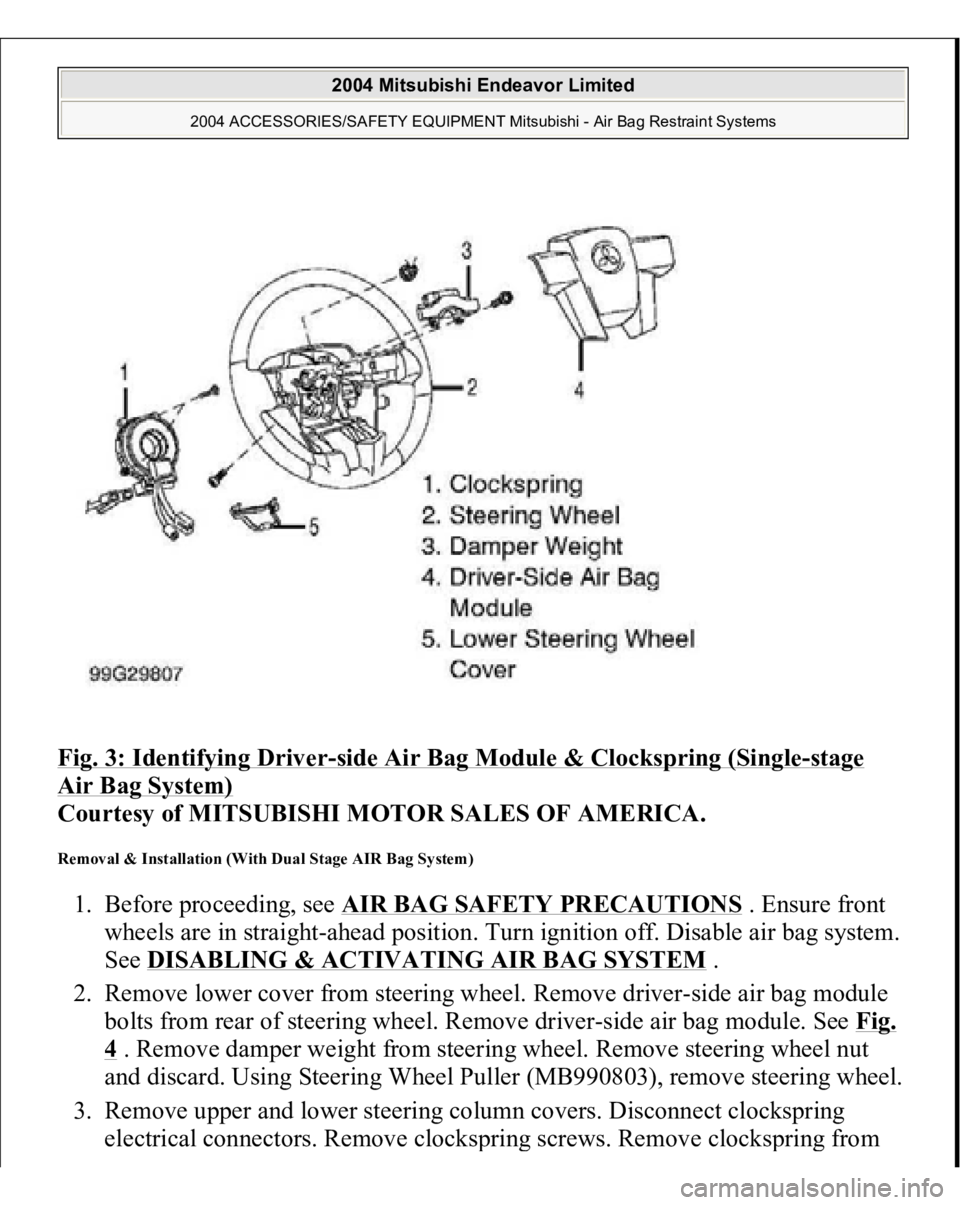
Fig. 3: Identifying Driver
-side Air Bag Module & Clockspring (Single
-stage
Air Bag System)
Courtesy of MITSUBISHI MOTOR SALES OF AMERICA.
Removal & Installation (With Dual Stage AIR Bag System) 1. Before proceeding, see
AIR BAG SAFETY PRECAUTIONS
. Ensure front
wheels are in straight-ahead position. Turn ignition off. Disable air bag system.
See
DISABLING & ACTIVATING AIR BAG SYSTEM
.
2. Remove lower cover from steering wheel. Remove driver-side air bag module
bolts from rear of steering wheel. Remove driver-side air bag module. See Fig.
4 . Remove damper weight from steering wheel. Remove steering wheel nut
and discard. Using Steering Wheel Puller (MB990803), remove steering wheel.
3. Remove upper and lower steering column covers. Disconnect clockspring
electrical connectors. Remove clocks
prin
g screws. Remove clocks
prin
g from
2004 Mitsubishi Endeavor Limited
2004 ACCESSORIES/SAFETY EQUIPMENT Mitsubishi - Air Bag Restraint Systems
Page 285 of 3870
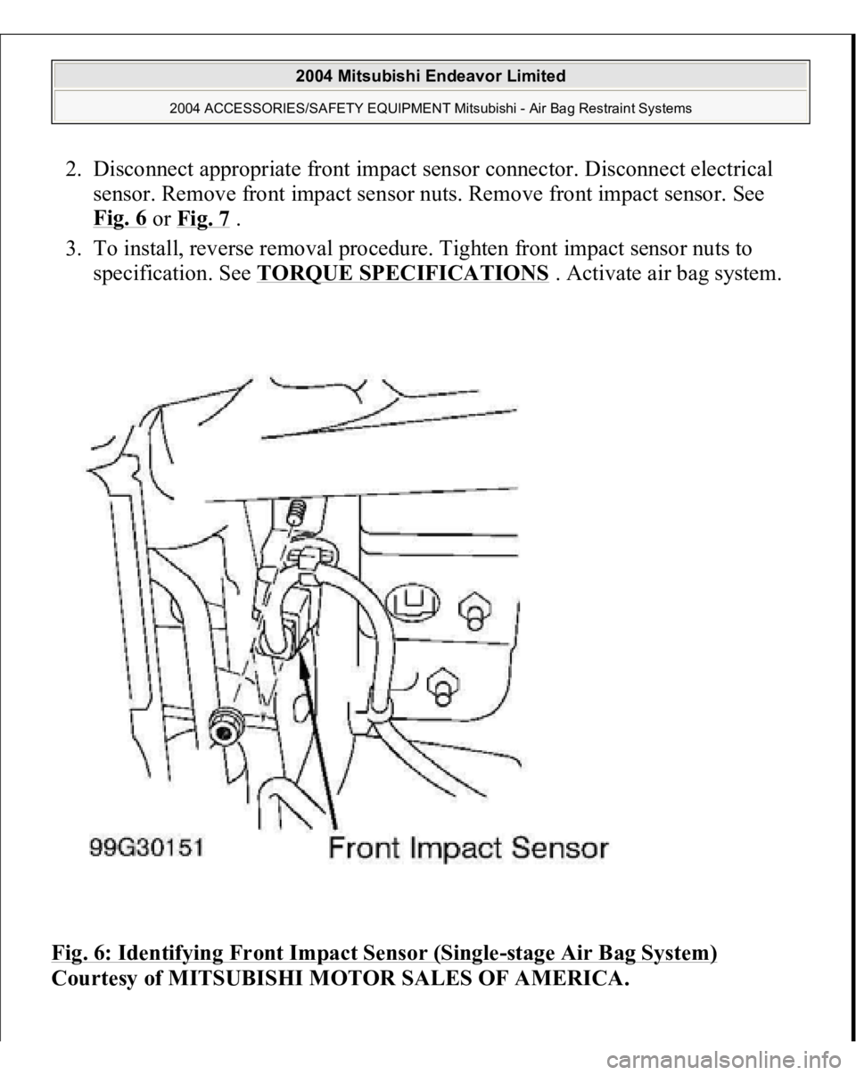
2. Disconnect appropriate front impact sensor connector. Disconnect electrical
sensor. Remove front impact sensor nuts. Remove front impact sensor. See
Fig. 6
or Fig. 7
.
3. To install, reverse removal procedure. Tighten front impact sensor nuts to
specification. See TORQUE SPECIFICATIONS
. Activate air bag system.
Fig. 6: Identifying Front Impact Sensor (Single
-stage Air Bag System)
Courtesy of MITSUBISHI MOTOR SALES OF AMERICA.
2004 Mitsubishi Endeavor Limited
2004 ACCESSORIES/SAFETY EQUIPMENT Mitsubishi - Air Bag Restraint Systems
Page 287 of 3870
CONSOLE ASSEMBL
Y . Remove left and right A-pillar trim panels.
Remove hood lock release handle.
3. Remove end panel. See Fig. 8
. Remove driver-side knee bolster. Remove fog
light switch. Remove steering column upper and lower covers. Remove
combination meter assembly. Remove center panel assembly. Remove air
vents. Remove radio panel. Remove AC-heater control assembly.
4. Remove hazard warning switch. Remove console meter hood. Remove multi-
center display unit. Remove audio components. Remove glove box assembly.
Remove left and right speaker covers. Remove speakers. Disconnect
clockspring and steering column switch connectors. Remove photo sensor and
photo sensor clamp.
5. Remove interior temperature sensor. Disconnect passenger-side air bag module
connector. Remove left and right center instrument panel brackets. Disconnect
remaining electrical connectors. Remove instrument panel nuts and bolts.
Remove instrument panel.
6. To install, reverse removal procedure. Tighten NEW steering wheel nut and
drive
r-side air ba
g module bolts to s
pecification. Activate air ba
g system.
2004 Mitsubishi Endeavor Limited
2004 ACCESSORIES/SAFETY EQUIPMENT Mitsubishi - Air Bag Restraint Systems