Page 238 of 442
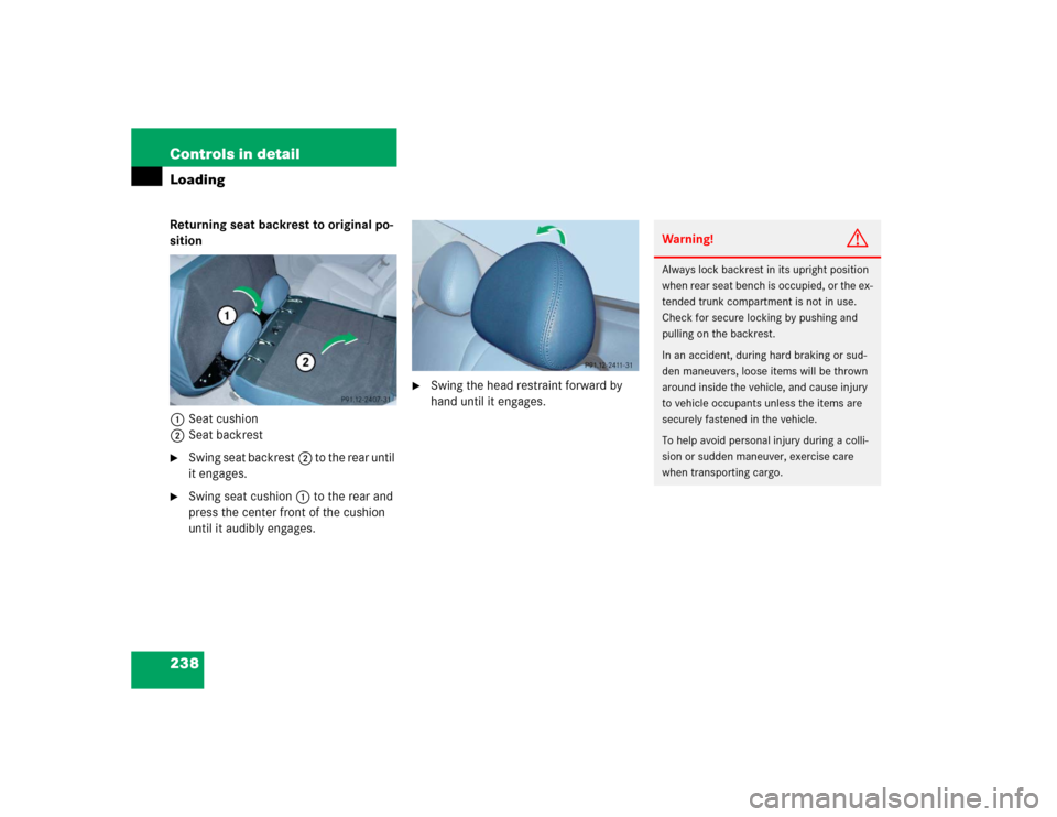
238 Controls in detailLoadingReturning seat backrest to original po-
sition
1Seat cushion
2Seat backrest�
Swing seat backrest2 to the rear until
it engages.
�
Swing seat cushion1 to the rear and
press the center front of the cushion
until it audibly engages.
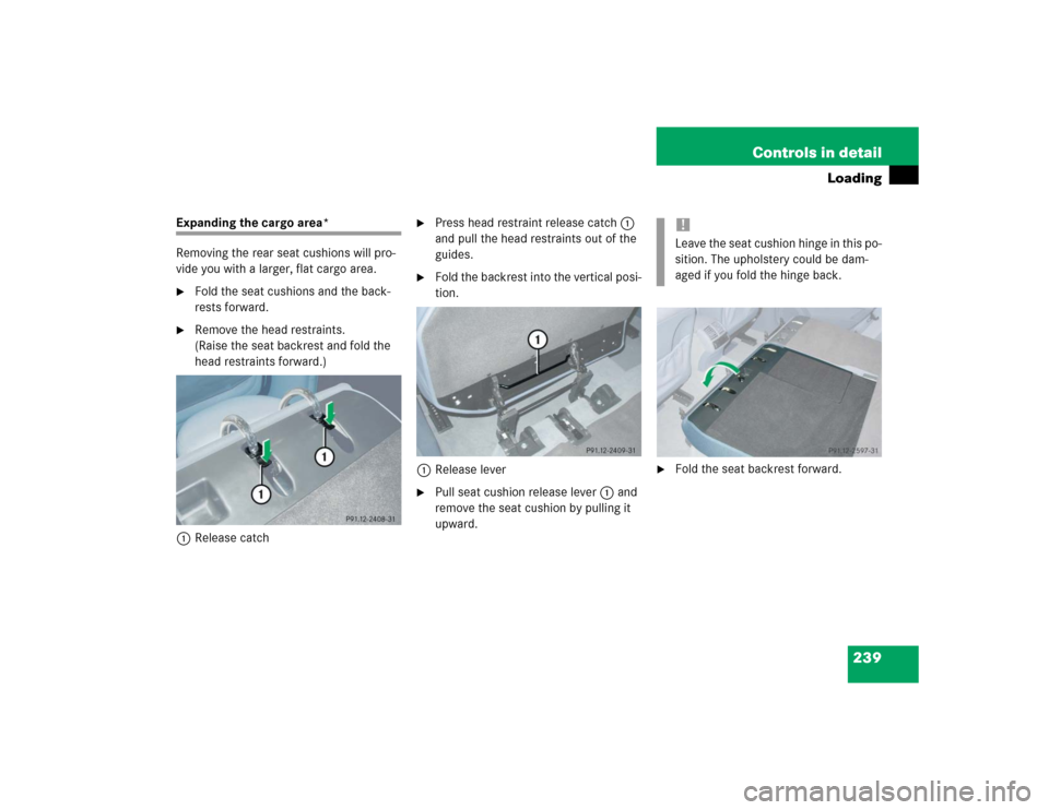
�
Swing the head restraint forward by
hand until it engages.
Warning!
G
Always lock backrest in its upright position
when rear seat bench is occupied, or the ex-
tended trunk compartment is not in use.
Check for secure locking by pushing and
pulling on the backrest.
In an accident, during hard braking or sud-
den maneuvers, loose items will be thrown
around inside the vehicle, and cause injury
to vehicle occupants unless the items are
securely fastened in the vehicle.
To help avoid personal injury during a colli-
sion or sudden maneuver, exercise care
when transporting cargo.
Page 239 of 442
239 Controls in detail
Loading
Expanding the cargo area*
Removing the rear seat cushions will pro-
vide you with a larger, flat cargo area.�
Fold the seat cushions and the back-
rests forward.
�
Remove the head restraints.
(Raise the seat backrest and fold the
head restraints forward.)
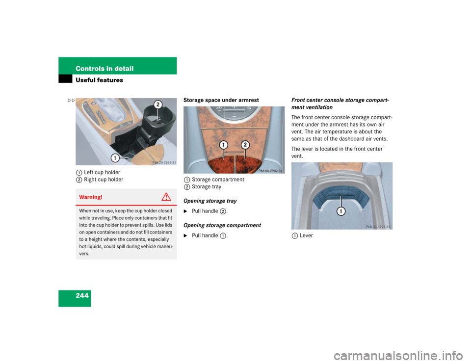
1Release catch
�
Press head restraint release catch1
and pull the head restraints out of the
guides.
�
Fold the backrest into the vertical posi-
tion.
1Release lever
�
Pull seat cushion release lever1 and
remove the seat cushion by pulling it
upward.
�
Fold the seat backrest forward.!Leave the seat cushion hinge in this po-
sition. The upholstery could be dam-
aged if you fold the hinge back.
Page 240 of 442

240 Controls in detailLoadingLoading instructions
The total load weight including vehicle oc-
cupants and luggage / cargo should not ex-
ceed the vehicle capacity weight indicated
on the certification tag which can be found
on the left door pillar.The handling characteristics of a fully load-
ed vehicle depend greatly on the load dis-
tribution. It is therefore recommended to
load the vehicle according to the illustra-
tions shown, with the heaviest items being
placed towards the front of the vehicle.
Always place items being carried against
front or rear seat backrests, and fasten
them as securely as possible.
The heaviest portion of the cargo should al-
ways be kept as low as possible since it in-
fluences the handling characteristics of
the vehicle.
Warning!
G
Always fasten items being carried as secure-
ly as possible.
In an accident, during hard braking or sud-
den maneuvers, loose items will be thrown
around inside the vehicle and can cause in-
jury to vehicle occupants unless the items
are securely fastened in the vehicle.
To help avoid personal injury during a colli-
sion or sudden maneuver, exercise care
when transporting cargo. Put luggage or car-
go in the trunk if possible. Do not pile lug-
gage or cargo higher than the seat backs.
Do not place anything on the rear-window
shelf.
Never drive vehicle with trunk open. Deadly
carbon monoxide (CO) gases may enter ve-
hicle interior resulting in unconsciousness
and death.
Page 244 of 442
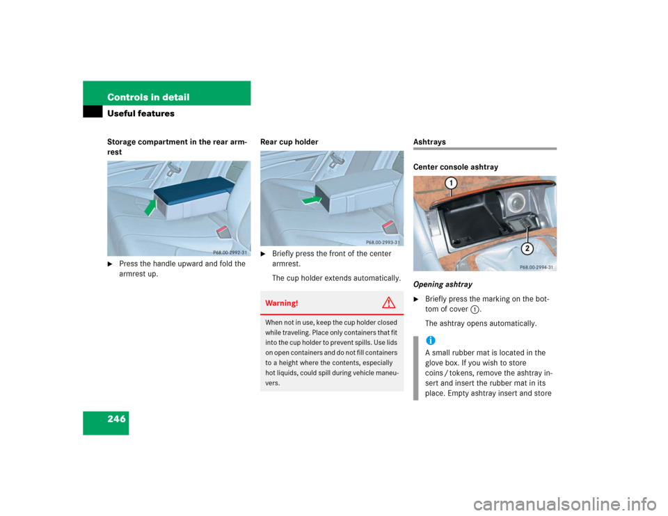
244 Controls in detailUseful features1Left cup holder
2Right cup holderStorage space under armrest
1Storage compartment
2Storage tray
Opening storage tray
�
Pull handle2.
Opening storage compartment
�
Pull handle1.Front center console storage compart-
ment ventilation
The front center console storage compart-
ment under the armrest has its own air
vent. The air temperature is about the
same as that of the dashboard air vents.
The lever is located in the front center
vent.
1Lever
Warning!
G
When not in use, keep the cup holder closed
while traveling. Place only containers that fit
into the cup holder to prevent spills. Use lids
on open containers and do not fill containers
to a height where the contents, especially
hot liquids, could spill during vehicle maneu-
vers.
��
Page 246 of 442
246 Controls in detailUseful featuresStorage compartment in the rear arm-
rest�
Press the handle upward and fold the
armrest up.Rear cup holder
�
Briefly press the front of the center
armrest.
The cup holder extends automatically.
Ashtrays
Center console ashtray
Opening ashtray�
Briefly press the marking on the bot-
tom of cover1.
The ashtray opens automatically.
Warning!
G
When not in use, keep the cup holder closed
while traveling. Place only containers that fit
into the cup holder to prevent spills. Use lids
on open containers and do not fill containers
to a height where the contents, especially
hot liquids, could spill during vehicle maneu-
vers.
iA small rubber mat is located in the
glove box. If you wish to store
coins / tokens, remove the ashtray in-
sert and insert the rubber mat in its
place. Empty ashtray insert and store
Page 247 of 442

247 Controls in detail
Useful features
Removing ashtray insert
�
Secure vehicle from movement by set-
ting the parking brake. Move the gear
selector lever to positionN.
Now you have more room to take out
the insert.
�
Push sliding button2 to the right and
hold.
�
Grip and remove insert from ashtray
frame.
Reinstalling ashtray insert
�
Install insert by pushing it back into
frame until it engages again.
Rear seat ashtrayOpening rear seat ashtray
�
Briefly press the top of the ashtray.
The ashtray opens.
Cigarette lighter
The cigarette lighter is located in the cen-
ter console compartment in front of the
armrest (
�page 26).
1Cigarette lighter
�
Turn ignition on.
�
Push in cigarette lighter1.
The lighter will pop out automatically
when hot. it in a convenient location in the vehi-
cle.
Warning!
G
Only use rubber mat in conjunction with
storing coins / tokens. Always remove rub-
ber mat and / or all other contents and rein-
sert ashtray insert before placing hot
cigarettes or other hot smoking materials in
this compartment.Warning!
G
Remove front ashtray only with vehicle
standing still. Set the parking brake to se-
cure vehicle from movement. Move gear se-
lector lever to positionN. With gear selector
lever in positionN, turn off the engine.
Page 251 of 442

251 Controls in detail
Useful features
Shortly after the completion of your ac-
quaintance call, you will receive a user ID
and password via first call mail. By visiting
www.mbusa.com and selecting “Tele Aid”
(USA only), you will have access to account
information, remote door unlock and
more.System self-check
Initially, after turning the ignition on, mal-
functions are detected and indicated (the
indicator lamps in the SOS button, the
Roadside Assistance button• and the
Information button¡ stay on longer
than ten seconds or do not come on). The
message
TELE AID – VISIT WORKSHOP!
ap-
pears for approximately 10 seconds in the
multifunction display.
iThe SOS button is located above the in-
terior rear view mirror.
The Roadside Assistance button•
and the Information button¡ are
located below the center armrest cov-
er.
!The Tele Aid system utilizes the cellular
network for communication and the
GPS (Global Positioning System) satel-
lites for vehicle location. If either of
these signals are unavailable, the
Tele Aid system may not function and if
this occurs, assistance must be sum-
moned by other means.
Warning!
G
If the indicator lamps in the SOS button, in
the Roadside Assistance button and / or in
the Information button remain illuminated
constantly in red and / or the message
TELE
AID - VISIT WORKSHOP!
is displayed in
the multifunction display after the system
self-check, a malfunction in the system has
been detected.
If a malfunction is indicated as outlined
above, the system may not operate as ex-
pected. Have the system checked at the
nearest Mercedes-Benz Center as soon as
possible.
Page 254 of 442
")
254 Controls in detailUseful featuresRoadside Assistance button•
Located below the center armrest cover is
the Roadside Assistance button•.�
Press and hold the button (for longer
than 2 seconds).
A call to a Mercedes-Benz Roadside As-
sistance dispatcher will be initiated.
The button will flash while the call is in
progress. The message
ROADSIDE AS-
SISTANCE – CONNECTING CALL
will ap-
pear in the multifunction display.
When the connection is established, the
message
ROADSIDE ASSISTANCE –
CALL CONNECTED
appears in the multifunc-
tion display. The Tele Aid system will trans-
mit data generating the vehicle
identification number, model, color and lo-
cation (subject to availability of cellular
and GPS signals).
A voice connection between the Roadside
Assistance dispatcher and the occupants
of the vehicle will be established. When a
voice connection is established, the
audio system mutes and the message
TELE AID – ROADSIDE ASSISTANCE
CALL ACTIVE
appears in the multifunction
display.
�
Describe the nature of the need for as-
sistance.
The Mercedes-Benz Roadside Assistance
dispatcher will either dispatch a qualified
Mercedes-Benz technician or arrange to
tow your vehicle to the nearest authorized
Mercedes-Benz Center. For services such
as labor and / or towing, charges may ap-
ply. Refer to the Roadside Assistance man-
ual for more information.
These programs are only available in the
USA:
�
Sign and Drive services: Services such
as a jump start, a few gallons of fuel or
the replacement of a flat tire with the
vehicle spare tire are obtainable.
�
Remote Vehicle Diagnostics: This func-
tion permits the Mercedes-Benz Road-
side Assistance dispatcher to
download malfunction codes and actu-
al vehicle data.
iThe indicator lamp on the Roadside As-
sistance button• remains illumi-
nated in red for approximately
10 seconds during the system
self-check after turning the ignition on
(together with the SOS button and the
Information button¡).
See system self-check (
�page 251)
when the indicator lamp does not come
on in red or stays on longer than ap-
proximately 10 seconds.
If the indicator lamp on the Roadside
Assistance button• is illuminated
continuously and there was no voice
connection to the Response Center es-
tablished, then the Tele Aid system
could not initiate a Roadside Assis-
tance call (e.g. the relevant cellular
phone network is not available). The
message
ROADSIDE ASSISTANCE –
CALL FAILED
appears in the multifunc-
tion display.