2004 ISUZU TF SERIES Manual codes
[x] Cancel search: Manual codesPage 32 of 4264
9A-12 SUPPLEMENTAL RESTRAINT SYSTEM
Diagnosis
WARNING: TO AVOID DEPLOYMENT WHEN
TROUBLESHOOTING THE SRS, DO NOT USE
ELECTRICAL TEST EQUIPMENT SUCH AS A
BATTERY–POWERED OR AC–POWERED
VOLTMETER, OHMMETER, ETC., OR ANY TYPE
OF ELECTRICAL EQUIPMENT OTHER THAN THAT
SPECIFIED IN THIS MANUAL. DO NOT USE A
NONPOWERED PROBE–TYPE TESTER.
INSTRUCTIONS IN THIS MANUAL MUST BE
FOLLOWED CAREFULLY, OTHERWISE
PERSONAL INJURY MAY RESULT.
Diagnostic Trouble Codes
The “SRS Diagnostic System Check” must always be
the starting point of any SRS diagnosis. The “SRS
Diagnostic System Check” checks for proper “AIR
BAG” warning lamp operation and checks for SRS
diagnostic trouble codes using the scan tool.
1. Current diagnostic trouble codes – Malfunctions
that are presently being detected. Curren
t
diagnostic trouble codes are stored in RAM
(Random Access Memory).
2. History diagnostic trouble codes – All malfunctions
detected since the last time the history memor
y
was cleared. History diagnostic trouble codes are
stored in EEPROM.
Scan Tool Diagnostics
A scan tool is used to read current and history
diagnostic trouble codes and to clear all diagnostic
trouble codes after a repair is completed. The scan
tool must be updated to communicate with the SRS
through a replaceable cartridge before it can be used
for SRS diagnostics. To use the scan tool, connect it
to the data link connector and turn the ignition switch
“ON”. The scan tool reads serial data from the SRS
control unit “Serial Data” line terminal “21” to the data
link connector terminal “2”.
Use Of Special Tools
WARNING: TO AVOID DEPLOYMENT WHEN
TROUBLESHOOTING THE SRS, DO NOT USE
ELECTRICAL TEST EQUIPMENT SUCH AS A
BATTERY–POWERED OR AC–POWERED
VOLTMETER, OHMMETER, ETC, OR ANY TYPE OF
ELECTRICAL EQUIPMENT OTHER THAN THAT
SPECIFIED IN THIS MANUAL. DO NOT USE A NON
POWERED PROBE–TYPE TESTER.
INSTRUCTIONS IN THIS MANUAL MUST BE
FOLLOWED CAREFULLY, OTHERWISE
PERSONAL INJURY MAY RESULT. YOU SHOULD
BE FAMILIAR WITH THE TOOLS LISTED IN THIS
SECTION UNDER THE HANDLING SRS SPECIAL
TOOLS.
You should be able to measure voltage and
resistance. You should be familiar with proper use of
a scan tool such as the Tech 2 Diagnostic Computer,
SRS Driver/Passenger Load Tool 5-8840-2421-0,
Connector Test Adapter Kit 5-8840-0385-0 and the
DVM (Digital Multimeter) 5-8840-0285-0.
Page 69 of 4264

SUPPLEMENTAL RESTRAINT SYSTEM 9A-49
The Tech 2 is used to read and clear SRS Diagnostic
Trouble Codes (DTCs). Refer to the Tech 2
Operators, Manual for specific information on how to
use the Tech 2.
5-8840-0385-0 Connector Test Adapter Kit
901RS151
The 5-8840-0385-0 Connector Test Adapter Kit must
be used whenever a diagnostic procedure requests
checking or probing a terminal. Using the appropriate
adapter will ensure that no damage to the terminal will
occur from the DVM prove, such as spreading or
bending. The adapter will also give an idea of
whether contact tension is sufficient, helping to find an
open or intermittent open due to poor terminal contact.
5-8840-2468-0 SRS Deployment Tool
901RW106
The 5-8840-2468-0 SRS Deployment Tool must be
used for deployment of the undeployed air bag.
5-8840-2420-0 SRS Deployment Fixture
901RV056
The 5-8840-2420-0 SRS Deployment Fixture must be
used for deployment of the undeployed passenger
side air bag.
5-8840-2796-0 SRS Adapter for Load Tool
901RW107
The 5-8840-2796-0 SRS Adapter for Load Tool must
be used with 5-8840-2421-0 SRS Driver/Passenger
Load Tool.
Page 73 of 4264
RESTRAINT CONTROL 9A1-3
Diagnostic Information
CAUTION: When fasteners are removed, always
reinstall them at the same location from which they
were removed. if a fastener needs to be replaced,
use the correct part number fastener for that
application. if the correct part number fastener is
not available, a fastener of equal size and strength
(or stronger) may be used. fasteners that are not
reused, and those requiring thread locking
compound will be called out. the correct torque
value must be used when installing fasteners that
require it. if the above conditions are not followed,
parts or system damage could result.
Diagnostic Procedures
WARNING: TO AVOID DEPLOYMENT WHEN
TROUBLESHOOTING THE SRS, DO NOT USE
ELECTRICAL TEST EQUIPMENT SUCH AS A
BATTERY-POWERED OR AC-POWERED
VOLTMETER, OHMMETER, ETC., OR ANY TYPE OF
ELECTRICAL EQUIPMENT OTHER THAN THAT
SPECIFIED IN THIS MANUAL. DO NOT USE A NON
POWERED, PROBE-TYPE TESTER.
INSTRUCTIONS IN THIS MANUAL MUST BE
FOLLOWED CAREFULLY, OTHERWISE PERSONAL
INJURY MAY RESULT.
The diagnostic procedures used in this section are
designed to aid in finding and repairing SRS problems.
Outlined below are the steps to find and repair SRS
problems quickly and effectively. Failure to carefully
follow these procedures may result in extended
diagnostic time, incorrect diagnosis and incorrect parts
replacement.
1. Perform The “SRS Diagnostic System Check”.
The “SRS Diagnostic System Check” should always
be the starting point of any SRS diagnostics. The
“SRS Diagnostic System Check” checks for prope
r
“AIR BAG” warning lamp operation and checks for
SRS trouble codes using both “Flash Code” and
“Scan Tool” Methods.
2. Refer To The Proper Diagnostic Chart As
Directed By The “SRS Diagnostic System
Check”.
The “SRS Diagnostic System Check” will lead you to
the correct chart to diagnose any SRS problems.
Bypassing these procedures may result in extended
diagnostic time, incorrect diagnosis and incorrect
parts replacement.
3. Repeat The “SRS Diagnostic System Check”
After Any Repair Or Diagnostic Procedures Have
Been Performed.
Preforming the “SRS Diagnostic System Check”
after all repair or diagnostic procedures will assure
that the repair has been made correctly and that no
other conditions exist.
Diagnostic Codes
The SRS control unit maintains a history record of all
diagnostic codes that have been detected since the
SRS codes were last cleared during service.
1. Active Codes - Faults that are presently detected this
ignition cycle. Active codes are stored in RAM
(Random Access Memory).
2. History Codes - All faults detected since the last time
the history fault memory was cleared. History codes
are stored in EEPROM. (Electronically Erasable
Programmable Read only Memory)
How To Read Trouble Codes
All codes (Active and history) can be read (or cleared)
by using a scan tool or equivalent.
If a PDT is not available, have the vehicle serviced by
HOLDEN dealer.
How To Clear Trouble Codes
Trouble codes can only be cleared by using a Scan
Tool. If a “scan tool” is not available then inform the
owner of the stored codes and suggest that the codes
are cleared upon the next visit to an Isuzu dealership.
Scan Tool Diagnostics
A scan tool can be used to read current and history
codes and to clear all history codes after a repair is
complete. The scan tool must be updated to
communicate with the SRS through a replaceable
cartridge or a manufacturer's update before it can be
used for SRS diagnostics. To use the scan tool,
connect it to the DLC connector and turn the ignition
switch “ON”. Then follow the manufacturer's directions
for communication with the SRS. The scan tool reads
serial data from the SRS control unitSRS control unit
“Serial Data” output (terminal 21) to the DLC connector
(terminal 2).
Basic Knowledge Required
Before using this section of the Service Manual, there is
some basic knowledge which will be required. Without
this knowledge, you will have trouble using the
diagnostic procedures in this section. Use care to
prevent harm or unwanted deployment. Read all
Page 74 of 4264

9A1-4 RESTRAINT CONTROL SYSTEM
cautions in the service manual and on warning labels
attached to SRS components.
Basic Electrical Circuits
You should understand the basic theory of electricity
including series and parallel circuits, and understand
the voltage drops across series resistors. You should
know the meaning of voltage (volts), current (amps),
and resistance (ohms). You should understand what
happens in a circuit with an open or a shorted wire. You
should be able to read and understand a wiring
diagram.
“Flash Code” Diagnostics
Flash code diagnostics can be used to read active
codes and to determine if history codes are present but
cannot be used to clear codes or read history codes.
Flash code diagnostics is enabled by grounding by
terminal 4 shorting to terminal 13 of the DLC connector
with the ignition switch “ON”. Grounding terminal 4 of
the DLC connector pulls the “Diagnostics Request”
input (Terminal 1) of the SRS control unit low and
signals the SRS control unit to enter the flash code
diagnostic display mode.
060R300052
Page 78 of 4264

9A1-8 RESTRAINT CONTROL SYSTEM
Circuit Description
When the ignition switch is first turned “ON”, “Ignition 1”
voltage is applied from the “SRS” fuse to the SRS
control unit at the “Ignition 1” input terminals “35”. The
SRS control unit responds by flashing the “AIR BAG”
warning lamp seven times, while performing tests on
the SRS.
Notes On System Check Chart
1.
The “AIR BAG” warning lamp should flash seven
times after ignition is first turned “ON”.
2.
After the “AIR BAG” warning lamp flashes seven
times, it should turn “OFF”
3.
This test checks for the proper operation of the
“Serial Data” line. This test will also determine
whether history diagnostic trouble codes are stored
and, if so, identify them.
4.
Improper operation of the “AIR BAG” warning lamp
is indicated. This test differentiates a warning lamp
stays “ON” condition from a warning lamp does not
come “ON” condition.
5.
This test checks for proper operation of the “Serial
Data” line. This test will also identify the stored
diagnostic trouble codes and whether they are
current or history.
Diagnostic Aids
The order in which diagnostic trouble codes are
diagnosed is very important. Failure to diagnose the
diagnostic trouble codes in the order specified may
result in extended diagnostic time, incorrect diagnosis
and incorrect parts replacement.
SRS Diagnostic System Check
Step Action Yes No
1 Note the “Air Bag” warning lamp as ignition switch is turned “ON.”
Does the “AIR BAG” warning lamp flash seven 7 times? Go to Step 2 Go to Step 3
2 Note the “AIR BAG” warning lamp after it flashed 7 times.
Does the “AIR BAG” warning lamp go “OFF”? Go to Step 4 Go to Step 5
3 Note the “AIR BAG” warning lamp as ignition switch is turned
“ON”.
Does the “AIR BAG” warning lamp come “ON” steady? Go to Chart B. Go to Chart C.
4
1.
Note the “AIR BAG” warning lamp as that ignition switch is
turned “ON.”
Ignition switch “OFF.”
2.
Connect a scan tool to data link connector.
3.
Follow direction given in the scan tool instruction manual.
Ignition switch “ON.”
4.
Request the SRS diagnostic trouble code display, recode all
history diagnostic trouble code(s). specify as such, on repair
order
Is (are) diagnostic trouble code(s) displayed? Ignition switch
“OFF.”
When DTC B1000 is
set, go to DTC
B1000 Chart.
For all other history
codes refer to
“Diagnostic Aids”
For that specific
DTC.
A history DTC
indicates the
malfunction has
been repaired or is
intermittent. SRS is functional
and free of
malfuncitons, no
further diagnosis is
required.
If scan tool indicated
“NO DATA
RECEIVED,” refer to
chassis electrical
section 8.
Page 1454 of 4264
6E–82 4JA1/4JH1 ENGINE DRIVEABILITY AND EMISSIONS
GENERAL SERVICE INFORMATION
Serviceability Issues
Non-OEM Parts
All of the OBD diagnostics have been calibrated to run
with OEM parts. Accordingly, if commercially sold
sensor or switch is installed, it makes a wrong diagnosis
and turns on the check engine lamp.
Aftermarket electronics, such as cellular phones,
stereos, and anti-theft devices, may radiate EMI into the
control system if they are improperly installed. This may
cause a false sensor reading and turn on the check
engine lamp.
Poor Vehicle Maintenance
The sensitivity of OBD diagnostics will cause the check
engine lamp to turn on if the vehicle is not maintained
properly. Restricted oil filters, fuel filters, and crankcase
deposits due to lack of oil changes or improper oil
viscosity can trigger actual vehicle faults that were not
previously monitored prior to OBD. Poor vehicle
maintenance can not be classified as a “non-vehicle
fault”, but with the sensitivity of OBD diagnostics,
vehicle maintenance schedules must be more closely
followed.
Related System Faults
Many of the OBD system diagnostics will not run if the
ECM detects a fault on a related system or component.
Visual/Physical Engine Compartment
Inspection
Perform a careful visual and physical engine
compartment inspection when performing any
diagnostic procedure or diagnosing the cause of an
emission test failure. This can often lead to repairing a
problem without further steps. Use the following
guidelines when performing a visual/physical
inspection:
Inspect all vacuum hoses for punches, cuts,
disconnects, and correct routing.
Inspect hoses that are difficult to see behind other
components.
Inspect all wires in the engine compartment for
proper connections, burned or chafed spots, pinched
wires, contact with sharp edges or contact with hot
exhaust manifolds or pipes.
Basic Knowledge of Tools Required
NOTE: Lack of basic knowledge of this powertrain
when performing diagnostic procedures could result in
an incorrect diagnosis or damage to powertrain
components. Do not attempt to diagnose a powertrain
problem without this basic knowledge.
A basic understanding of hand tools is necessary to
effectively use this section of the Service Manual.
ON-BOARD DIAGNOSTIC (OBD)
On-Board Diagnostic (Self Diagnosis
System) Tests
A diagnostic test is a series of steps, the result of which
is a pass or fail reported to the diagnostic ex ecutive.
When a diagnostic test reports a pass result, the
diagnostic ex ecutive records the following data:
The diagnostic test has been completed since the
last ignition cycle.
The diagnostic test has passed during the current
ignition cycle.
The fault identified by the diagnostic test is not
currently active.
When a diagnostic test reports a fail result, the
diagnostic ex ecutive records the following data:
The diagnostic test has been completed since the
last ignition cycle.
The fault identified by the diagnostic test is currently
active.
The fault has been active during this ignition cycle.
The operating conditions at the time of the failure.
The Diagnostic Executive
The Diagnostic Executive is a unique segment of
software which is designed to coordinate and prioritize
the diagnostic procedures as well as define the protocol
for recording and displaying their results. The main
responsibilities of the Diagnostic Ex ecutive are listed as
follow s:
Commanding the check engine lamp on and off
DTC logging and clearing
Current status information on each diagnostic
Diagnostic Information
The diagnostic charts and functional checks are
designed to locate a faulty circuit or component through
a process of logical decisions. The charts are prepared
with the requirement that the vehicle functioned
correctly at the time of assembly and that there are not
multiple faults present.
There is a continuous self-diagnosis on certain control
functions. This diagnostic capability is complemented
by the diagnostic procedures contained in this manual.
The language of communicating the source of the
malfunction is a system of diagnostic trouble codes.
When a malfunction is detected by the control module, a
diagnostic trouble code is set and the check engine
lamp is illuminated.
Check Engine Lamp
The check engine lamp looks the same as the check
engine lamp you are already familiar with, the “Check
Engine” lamp.
Basically, the check engine lamp is turned on when the
Page 1541 of 4264
4JA1/4JH1 ENGINE DRIVEABILITY AND EMISSIONS 6E–169
moving connectors and wiring harness related to the
sensor.
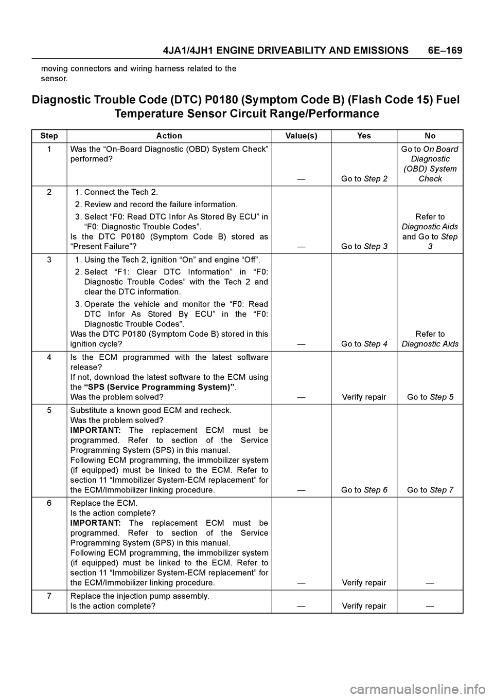
Diagnostic Trouble Code (DTC) P0180 (Sy mptom Code B) (Flash Code 15) Fuel
Temperature Sensor Circuit Range/Performance
Step Action Value(s) Yes No
1Was the “On-Board Diagnostic (OBD) System Check”
performed?
—Go to Step 2Go to On Board
Diagnostic
(OBD) System
Check
2 1. Connect the Tech 2.
2. Review and record the failure information.
3. Select “F0: Read DTC Infor As Stored By ECU” in
“F0: Diagnostic Trouble Codes”.
Is the DTC P0180 (Symptom Code B) stored as
“Present Failure”?—Go to Step 3Refer to
Diagnostic Aids
and Go to Step
3
3 1. Using the Tech 2, ignition “On” and engine “Off”.
2. Select “F1: Clear DTC Information” in “F0:
Diagnostic Trouble Codes” with the Tech 2 and
clear the DTC information.
3. Operate the vehicle and monitor the “F0: Read
DTC Infor As Stored By ECU” in the “F0:
Diagnostic Trouble Codes”.
Was the DTC P0180 (Symptom Code B) stored in this
ignition cycle?—Go to Step 4Refer to
Diagnostic Aids
4 Is the ECM programmed with the latest software
release?
If not, download the latest software to the ECM using
the “SPS (Service Programming System)”.
Was the problem solved?—Verify repair Go to Step 5
5 Substitute a known good ECM and recheck.
Was the problem solved?
IMPORTANT: The replacement ECM must be
programmed. Refer to section of the Service
Programming System (SPS) in this manual.
Following ECM programming, the immobilizer system
(if equipped) must be linked to the ECM. Refer to
section 11 “Immobilizer System-ECM replacement” for
the ECM/Immobilizer linking procedure. —Go to Step 6Go to Step 7
6 Replace the ECM.
Is the action complete?
IMPORTANT: The replacement ECM must be
programmed. Refer to section of the Service
Programming System (SPS) in this manual.
Following ECM programming, the immobilizer system
(if equipped) must be linked to the ECM. Refer to
section 11 “Immobilizer System-ECM replacement” for
the ECM/Immobilizer linking procedure.—Verify repair—
7 Replace the injection pump assembly.
Is the action complete?—Verify repair—
Page 1549 of 4264
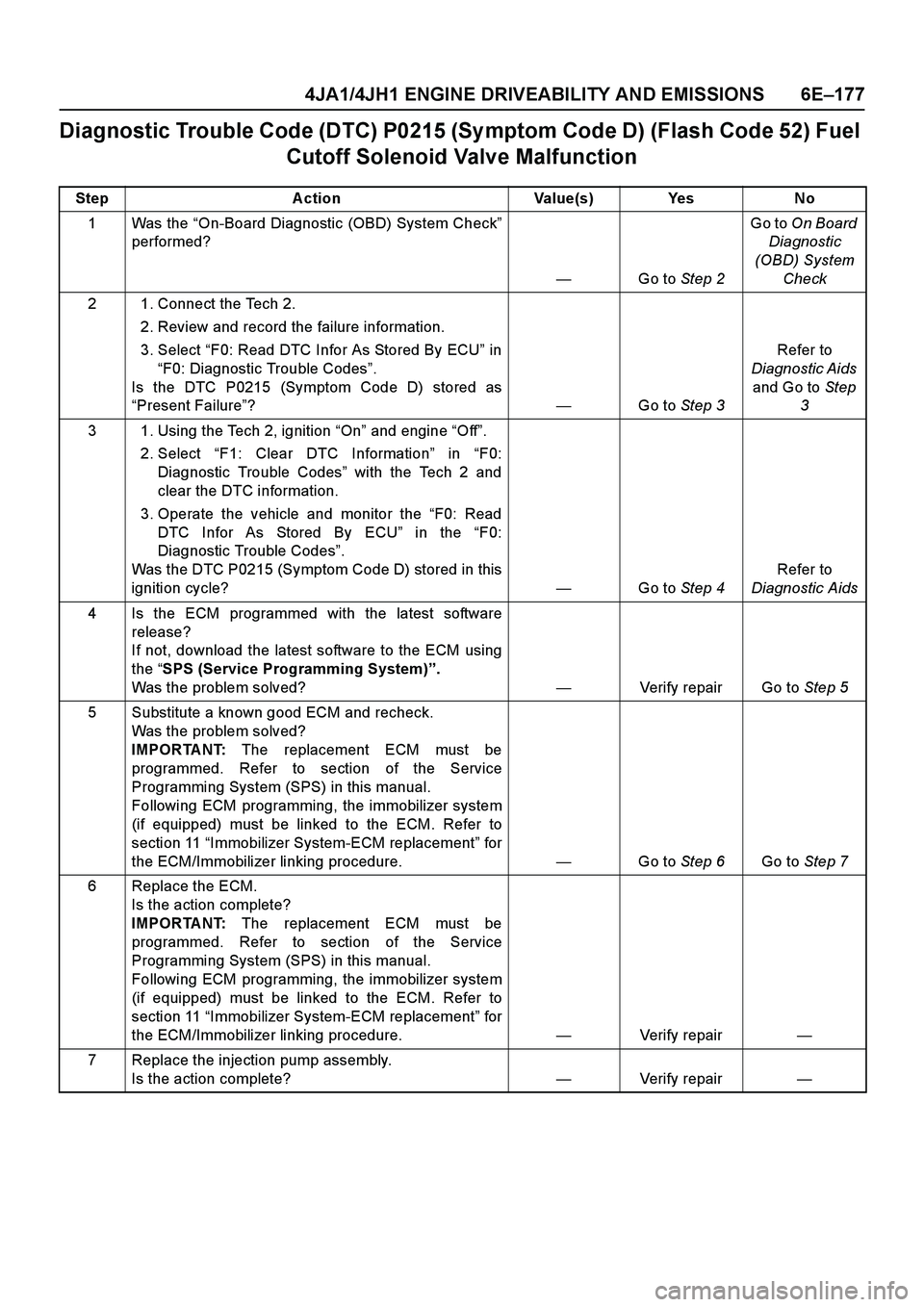
4JA1/4JH1 ENGINE DRIVEABILITY AND EMISSIONS 6E–177
Diagnostic Trouble Code (DTC) P0215 (Sy mptom Code D) (Flash Code 52) Fuel
Cutoff Solenoid Valve Malfunction
Step Action Value(s) Yes No
1Was the “On-Board Diagnostic (OBD) System Check”
performed?
—Go to Step 2Go to On Board
Diagnostic
(OBD) System
Check
2 1. Connect the Tech 2.
2. Review and record the failure information.
3. Select “F0: Read DTC Infor As Stored By ECU” in
“F0: Diagnostic Trouble Codes”.
Is the DTC P0215 (Symptom Code D) stored as
“Present Failure”?—Go to Step 3Refer to
Diagnostic Aids
and Go to Step
3
3 1. Using the Tech 2, ignition “On” and engine “Off”.
2. Select “F1: Clear DTC Information” in “F0:
Diagnostic Trouble Codes” with the Tech 2 and
clear the DTC information.
3. Operate the vehicle and monitor the “F0: Read
DTC Infor As Stored By ECU” in the “F0:
Diagnostic Trouble Codes”.
Was the DTC P0215 (Symptom Code D) stored in this
ignition cycle?—Go to Step 4Refer to
Diagnostic Aids
4 Is the ECM programmed with the latest software
release?
If not, download the latest software to the ECM using
the “SPS (Service Programming System)”.
Was the problem solved?—Verify repair Go to Step 5
5 Substitute a known good ECM and recheck.
Was the problem solved?
IMPORTANT: The replacement ECM must be
programmed. Refer to section of the Service
Programming System (SPS) in this manual.
Following ECM programming, the immobilizer system
(if equipped) must be linked to the ECM. Refer to
section 11 “Immobilizer System-ECM replacement” for
the ECM/Immobilizer linking procedure. —Go to Step 6Go to Step 7
6 Replace the ECM.
Is the action complete?
IMPORTANT: The replacement ECM must be
programmed. Refer to section of the Service
Programming System (SPS) in this manual.
Following ECM programming, the immobilizer system
(if equipped) must be linked to the ECM. Refer to
section 11 “Immobilizer System-ECM replacement” for
the ECM/Immobilizer linking procedure.—Verify repair—
7 Replace the injection pump assembly.
Is the action complete?—Verify repair—