Page 4105 of 4264
DIAGNOSIS (JR405E) 7A2-113
Step Action Yes No
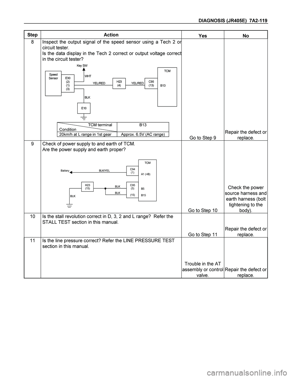
6 Inspect the output voltage and throttle opening signal of the
throttle position sensor using a Tech 2 or circuit tester.
Is a voltage value in proportion to the throttle opening output?
TPSTCM
A16
C56
(28)C94
(16) RED/ WHT
C56
(49)
(38)
(57)
(69)ECM
A47 (GND)
A35 (Out put )
A26
A55 (+5V)
A69 (I dl e SW)
Go to Step 7
Repair the defect or
replace.
8 Check of power supply to and earth of TCM.
Are the power supply and earth proper?
TCM
A1 (+B)
B5
B15
H23
(15)C95
(5)
(15) BLK/YEL
BLK BLK Battery
C94
(1)
BLK
Go to Step 9
Check the power
source harness and
earth harness (bolt
tightening to the
body).
9 Is the stall revolution correct in D, 3, 2 and L range? Refer the
STALL TEST section in this manual.
Go to Step 10
Repair the defect or
replace.
10 Is the line pressure correct? Refer the LINE PRESSURE TEST
section in this manual.
Trouble in the AT
assembly or control
valve.
Repair the defect or
replace.
Page 4111 of 4264

DIAGNOSIS (JR405E) 7A2-119
Step Action Yes No
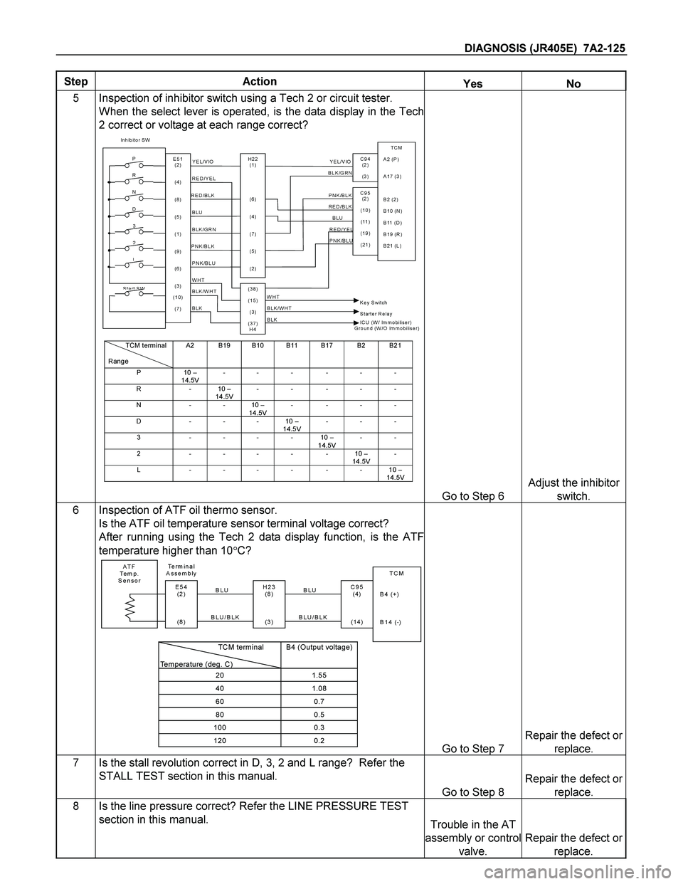
8 Inspect the output signal of the speed sensor using a Tech 2 or
circuit tester.
Is the data display in the Tech 2 correct or output voltage correct
in the circuit tester?
Speed
SensorTCM
B13
H23
(4)C95
(13)E30
(2)
(1)
(3)
E10
Key SW
YEL/RED WHT
BLKYEL/RED
TCM terminal
ConditionB13
20km/h at L range in 1st gear Approx. 6.5V (AC range)Go to Step 9
Repair the defect or
replace.
9 Check of power supply to and earth of TCM.
Are the power supply and earth proper?
TCM
A1 (+B)
B5
B15
H23
(15)C95
(5)
(15) BLK/YEL
BLK BLK Battery
C94
(1)
BLK
Go to Step 10
Check the power
source harness and
earth harness (bolt
tightening to the
body).
10 Is the stall revolution correct in D, 3, 2 and L range? Refer the
STALL TEST section in this manual.
Go to Step 11
Repair the defect or
replace.
11 Is the line pressure correct? Refer the LINE PRESSURE TEST
section in this manual.
Trouble in the AT
assembly or control
valve.
Repair the defect or
replace.
Page 4115 of 4264
DIAGNOSIS (JR405E) 7A2-123
Step Action Yes No
6 Check of power supply to and earth of TCM.
Are the power supply and earth proper?
TCM
A1 (+B)
B5
B15
H23
(15)C95
(5)
(15) BLK/YEL
BLK BLK Battery
C94
(1)
BLK
Go to Step 7
Check the power
source harness and
earth harness (bolt
tightening to the
body).
7 Inspection of speed sensor and turbine sensor
Have the speed sensor and turbine sensor failed at the same
time? (No DTC is stored at the time of trouble) Repair the defect or
replace. Go to Step 8
8 Is the stall revolution correct in D, 3, 2 and L range? Refer the
STALL TEST section in this manual.
Go to Step 9
Repair the defect or
replace.
9 Is the line pressure correct? Refer the LINE PRESSURE TEST
section in this manual. Trouble in the AT
assembly or control
valve.
Repair the defect or
replace.
Page 4117 of 4264

DIAGNOSIS (JR405E) 7A2-125
Step Action Yes No
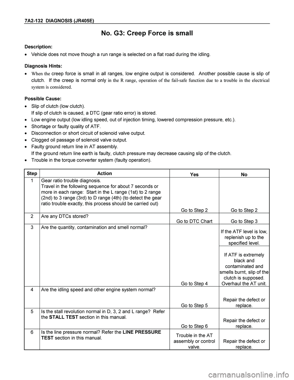
5 Inspection of inhibitor switch using a Tech 2 or circuit tester.
When the select lever is operated, is the data display in the Tech
2 correct or voltage at each range correct?
Inhibitor SW
TCM
A2 (P)
A17 (3)
B2 (2)
B10 (N)
B11 (D)
B19 (R)
B21 (L)
C95
(2 )
(10)
(11 )
(19)
(21) Y E L /V IO
RED/BLK
BLUBLK/GRN
Starter Relay
C94
(2 )
(3 )
BH22
(1)
(6)
(4)
(7)
(5)
(2) P
2
R
N
D
3
L
Start SW
PNK/BLU
E51
(2)
(4)
(8)
(5)
(1)
(9)
(6)
(3)
(10)
(7)
(38)
(15)
(3)
(37)
H4PNK/BLK
RED/YEL Y E L /V IO
BLK/GRN
PNK/BLK RED/BLK
BLU RED/YEL
PNK/BLU
BLK/WHT
BLK
BLK BLK/WHT Key Switch WHT
WHT
ICU (W/ Immobilis e r)
Ground (W/O Immobilis e r)
TCM terminal
RangeA2 B19 B10 B11 B17 B2 B21
P10 –
14.5V-- - - - -
R-10 –
14.5V-- ---
N--10 –
14.5V----
D - - - 10 –
14.5V---
3----10 –
14.5V--
2-----10 –
14.5V-
L------10 –
14.5V
Go to Step 6
Adjust the inhibitor
switch.
6 Inspection of ATF oil thermo sensor.
Is the ATF oil temperature sensor terminal voltage correct?
After running using the Tech 2 data display function, is the ATF
temperature higher than 10�C?
ATF
Te m p .
SensorTCM
B4 (+)
B14 (-)
H23
(8 )
(3 )C95
(4)
(14) BLU Te rm i n a l
Assembly
BLU/BLKE54
(2 )
(8 ) BLU
BLU/BLK
TCM terminal
Temperature (deg. C)
B4 (Output voltage)
201.55
401.08
600.7
800.5
1000.3
1200.2Go to Step 7
Repair the defect or
replace.
7 Is the stall revolution correct in D, 3, 2 and L range? Refer the
STALL TEST section in this manual.
Go to Step 8
Repair the defect or
replace.
8 Is the line pressure correct? Refer the LINE PRESSURE TEST
section in this manual. Trouble in the AT
assembly or control
valve.
Repair the defect or
replace.
Page 4121 of 4264
DIAGNOSIS (JR405E) 7A2-129
Step Action Yes No
6 Inspect the output voltage and throttle opening signal of the
throttle position sensor using a Tech 2 or circuit tester.
Is a voltage value in proportion to the throttle opening output?
TPSTCM
A16
C56
(28)C94
(16) RED/ WHT
C56
(49)
(38)
(57)
(69)ECM
A47 (GND)
A35 (Out put )
A26
A55 (+5V)
A69 (I dl e SW)
Go to Step 7
Repair the defect or
replace.
7 Check of power supply to and earth of TCM.
Are the power supply and earth proper?
TCM
A1 (+B)
B5
B15
H23
(15)C95
(5)
(15) BLK/YEL
BLK BLK Battery
C94
(1)
BLK
Go to Step 8
Check the power
source harness and
earth harness (bolt
tightening to the
body).
8 Is the stall revolution correct in D, 3, 2 and L range? Refer the
STALL TEST section in this manual.
Go to Step 6
Repair the defect or
replace.
9 Is the line pressure correct? Refer the LINE PRESSURE TEST
section in this manual. Trouble in the AT
assembly or control
valve.
Repair the defect or
replace.
Page 4124 of 4264

7A2-132 DIAGNOSIS (JR405E)
No. G3: Creep Force is small
Description:
� Vehicle does not move though a run range is selected on a flat road during the idling.
Diagnosis Hints:
� When the creep force is small in all ranges, low engine output is considered. Another possible cause is slip of
clutch. If the creep is normal only in the R range, operation of the fail-safe function due to a trouble in the electrical
system is considered.
Possible Cause:
� Slip of clutch (low clutch).
If slip of clutch is caused, a DTC (gear ratio error) is stored.
� Low engine output (low idling speed, out of injection timing, lowered compression pressure, etc.).
� Shortage or faulty quality of ATF.
� Disconnection or short circuit of solenoid valve output.
� Clogged oil passage of solenoid valve output.
� Faulty ground return line in AT assembly.
If the ground return line earth is faulty, clutch pressure may decrease causing slip of the clutch.
� Trouble in the torque converter system (faulty operation).
Step Action Yes No
1 Gear ratio trouble diagnosis.
Travel in the following sequence for about 7 seconds or
more in each range: Start in the L range (1st) to 2 range
(2nd) to 3 range (3rd) to D range (4th) (to detect the gear
ratio trouble exactly, this process should be carried out)
Go to Step 2 Go to Step 2
2 Are any DTCs stored?
Go to DTC Chart Go to Step 3
3 Are the quantity, contamination and smell normal? If the ATF level is low,
replenish up to the
specified level.
Go to Step 4
If ATF is extremely
black and
contaminated and
smells burnt, slip of the
clutch is supposed.
Overhaul the AT unit.
4 Are the idling speed and other engine system normal?
Go to Step 5
Repair the defect or
replace.
5 Is the stall revolution normal in D, 3, 2 and L range? Refer
the STALL TEST section in this manual.
Go to Step 6
Repair the defect or
replace.
6 Is the line pressure normal? Refer the LINE PRESSURE
TEST section in this manual. Trouble in the AT
assembly or control
valve.
Repair the defect or
replace.
Page 4137 of 4264

DIAGNOSIS (JR405E) 7A2-145
5. R range test.
1) Shift into the R range and while starting at full throttle,
check for slipping.
6.P range test.
1) Stop the vehicle on a grade and after shifting into the P
range, release the parking brake. Then check to see tha
t
the parking lock pawl holds the vehicle in place.
Select
Lever
Position
Gear
Position
Gear
Shift
P �
�� � �
�� �
R Reverse �
�� �
N �
�� � �
�� �
D 1st
2nd
3rd
4th
3 1st
2nd
3rd
4th(*1)
2 1st
2nd
3rd(*1)
4th(*1)
L 1st
2nd(*1)
3rd(*1)
4th(*1)
Evaluation
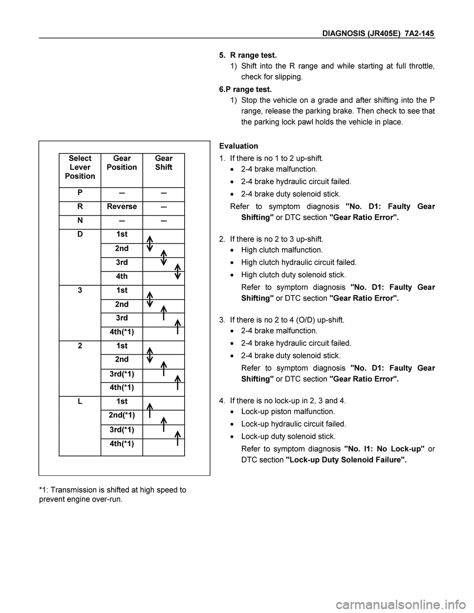
1. If there is no 1 to 2 up-shift.
� 2-4 brake malfunction.
� 2-4 brake hydraulic circuit failed.
� 2-4 brake duty solenoid stick.
Refer to symptom diagnosis "No. D1: Faulty Gea
r
Shifting" or DTC section "Gear Ratio Error".
2. If there is no 2 to 3 up-shift.
� High clutch malfunction.
� High clutch hydraulic circuit failed.
� High clutch duty solenoid stick.
Refer to symptom diagnosis "No. D1: Faulty Gea
r
Shifting" or DTC section "Gear Ratio Error".
3. If there is no 2 to 4 (O/D) up-shift.
� 2-4 brake malfunction.
� 2-4 brake hydraulic circuit failed.
� 2-4 brake duty solenoid stick.
Refer to symptom diagnosis "No. D1: Faulty Gea
r
Shifting" or DTC section "Gear Ratio Error".
4. If there is no lock-up in 2, 3 and 4.
� Lock-up piston malfunction.
� Lock-up hydraulic circuit failed.
� Lock-up duty solenoid stick.
Refer to symptom diagnosis "No. I1: No Lock-up"o
r
DTC section "Lock-up Duty Solenoid Failure".
*1: Transmission is shifted at high speed to
prevent engine over-run.
Page 4138 of 4264
7A2-146 DIAGNOSIS (JR405E)
5. If there is no reverse.
� Reverse clutch malfunction.
� Reverse clutch hydraulic circuit failed.
� Low & reverse brake hydraulic circuit failed.
� Low & reverse brake duty solenoid stick.
Refer to symptom diagnosis "No. A2: Vehicle Dose Not
Run in R Range" or DTC section "Low & Reverse
Brake Duty Solenoid Failure".
6. If there is no parking.
� Parking pawl malfunction.
Refer to symptom diagnosis "No. G1: Vehicle Moves in
P Range or Parking Gear in Not Disengaged othe
r
than P Range".
NOTE:
The check for the cause of abnormal noise and vibration
must be made with extreme care as it could also be due to
loss of balance in propeller shaft, differential, the torque
converter, etc. Or insufficient bending, rigidity, etc. in the
powertran.