Page 3724 of 4264
 (V6 3.5L)
Diagnostic Aids
Inspect the wiring for poor electrical connection at
the TCM. Look for possible bent, backed out,
deformed or damaged")
7A2-44 TRANSMISSION CONTROL SYSTEM (AW30–40LE) (V6 3.5L)
Diagnostic Aids
Inspect the wiring for poor electrical connection at
the TCM. Look for possible bent, backed out,
deformed or damaged terminals. Check for weak
terminal tension as well. Also check for a chafed wire
that could short to bare metal or other wiring. Inspect
for a broken wire inside the insulation.
When diagnosing for a possible intermittent short o
r
open condition, move the wiring harness while
observing test equipment for a change.
Check oil temperature sensor for proper mounting
and adjustment.
DTC P0712 (FLASHING CODE 15) Transmission Oil Temperature Sensor
Circuit Low Input
Step Action Value(s) YES NO
1
Was the powertrain On-Board Diagnostic (OBD)
System Check performed? — Go to Step 2 Go to OBD
System Check
2 Perform the transmission fluid checking procedure.
Refer to checking Transmission Fluid level and
Condition in Automatic Transmission 7A section.
Was the fluid checking procedure performed ? — Go to Step 3 Refer to
Checking
Transmission
Fluid level and
Condition in
Automatic
Transmission
(AW30-40LE)
section
3
1. Install the scan tool.
2. Key “ON"
3. Review and record scan tool data.
4. Operate the vehicle with in scan tool data.
Does the scan tool indicate DTC P0712 ? — Go to Step 4 Refer to
Diagnostic Aids
4 Measure the voltage of the transmission fluid
temperature sensor by the J39200 DMM.
1. Key “OFF".
2. Disconnect the oil temperature sensor connector.
3. Key “ON".
4. Connect the J39200 DMM to the each terminal of
the oil temperature sensor connector E83-2 and
E83-1.
Does the scan tool indicate less than specified
value ? 5V Go to Step 5 Go to Step 6
5 Replace the transmission fluid temperature sensor.
Is the action complete ? — Verify repair —
Page 3727 of 4264
 (V6 3.5L) 7A2-47
Diagnostic Aids
Inspect the wiring for poor electrical connection at
the TCM. Look for possible bent, backed out,
deformed or damaged")
TRANSMISSION CONTROL SYSTEM (AW30–40LE) (V6 3.5L) 7A2-47
Diagnostic Aids
Inspect the wiring for poor electrical connection at
the TCM. Look for possible bent, backed out,
deformed or damaged terminals. Check for weak
terminal tension as well. Also check for a chafed wire
that could short to bare metal or other wiring. Inspect
for a broken wire inside the insulation.
When diagnosing for a possible intermittent short o
r
open condition, move the wiring harness while
observing test equipment for a change.
Check oil temperature sensor for proper mounting
and adjustment.
DTC P0713 (FLASHING CODE 16) Transmission Oil Temperature Sensor
Circuit Hight Input
Step Action Value(s) YES NO
1
Was the powertrain On-Board Diagnostic (OBD)
System Check performed ? — Go to Step 2 Go to OBD
System check
2 Perform the transmission fluid checking procedure.
Refer to Checking Transmission Fluid Level and
condition Automatic Transmission7A section.
Was the fluid checking procedure performed ? — Go to Step 3 Refer to
checking
Transmission
Fluid Level and
Condition
Automatic
Transmission
(AW30-40LE)
section
3
1. Install the scan tool ?
2. Key “ON"
3. Review and record scan tool date.
4. Operate the vehicle with in scan tool data.
Does the scan tool indicator DTC P0713 ? — Go to Step 4 Go to
Diagnostic Aids
4 Observe the voltage of the transmission fluid
temperature sensor on the TECH2 data.
1. Key “OFF".
2. Disconnect the transmission fluid temperature
sensor connector E-83
3. Install a fused jumper wire from terminal E83-2 to
E83-1 on the mission harness.
4. Key “ON".
Does the scan tool indicate more than specified
value ? 0.4V Go to Step 5 Go to Step 6
5 Replace the transmission fluid temperature sensor .
If the action complete ? — Verify repair —
Page 3739 of 4264
 (V6 3.5L) 7A2-59
DTC stored.
Conditions For Clearing The DTC
The DTC can be cleared from the TCM history by
using a scan tool.
The DTC will be")
TRANSMISSION CONTROL SYSTEM (AW30–40LE) (V6 3.5L) 7A2-59
DTC stored.
Conditions For Clearing The DTC
The DTC can be cleared from the TCM history by
using a scan tool.
The DTC will be cleared from history when the
vehicle has achieved 40 warm-up cycles without a
failure reported.
After more than 1 second has elapsed after the
ignition key has been turned “ON", short between
No.11 and No.4 (ground) of DLC (Data Link
Connector). Then, after 1 second, but within 6
seconds, discontinue shorting.
Diagnostic Aids
Inspect the wiring for poor electrical connection at
the TCM. Look for possible bent, backed out,
deformed or damaged terminals. Check for weak
terminal tension as well. Also check for a chafed wire
that could short to bare metal or other wiring.
Inspect for a broken wire inside the insulation.
When diagnosing for a possible intermittent short o
r
open condition, move the wiring harness while
observing test equipment for a change.
DTC P0748 (FLASHING CODE 35) Pressure Control Solenoid Malfunction
Step Action Value(s) YES NO
1
Was the Powertrain On-Board Diagnostic (OBD)
System Check performed? — Go to Step 2 Go to OBD
System Check
2
1. Install the scan tool.
2. Key “ON".
3. Review and record scan tool data.
4. Operate the vehicle within scan tool data.
Does the scan tool indicate DTC P0748? — Go to Step 3 Refer to
Diagnostic Aids
3 Perform the transmission fluid checking procedure.
Refer to checking Transmission Fluid level and
Condition in Automatic Transmission 7A section.
Was the fluid checking procedure performed? — Go to Step 4 Refer to
checking
Transmission
Fluid level and
Condition in
Automatic
Transmission
(AW30-40LE)
section
Page 3772 of 4264

Evaluation
i. If there is no 1 �
2 upshift:
Solenoid S2 is stuck
1 –2 shift valve is stuck
ii. If there is no 2 �
3 upshift:
")
7A3-16 ON-VEHICLE SERVICE (AW30 –40LE)
Evaluation
i. If there is no 1 �
2 upshift:
Solenoid S2 is stuck
1 –2 shift valve is stuck
ii. If there is no 2 �
3 upshift:
Solenoid S1 is stuck
2 –3 shift valve is stuck
iii. If there is no 3 �
OD upshift (throttle valve opening
1/2):
Solenoid S2 is stuck
3 –OD shift valve is stuck
iv. If the shift point is defective: Refer to TROUBLESHOOTING CHART in this
section.
v. If the lock-up is defective: Refer to TROUBLESHOOTING CHART in this
section.
2. In the same manner, check the shock and slip at the 1 �
2, 2 �
3 and 3 �
OD upshifts.
NOTE: Drive the vehicle on level ground.
Evaluation
If the shock is excessive:
Refer to TROUBLESHOOTING CHART in this section.
3. Run at “D" range lock-up or OD gear and check fo
r
abnormal noise and vibration.
NOTE: The check for the cause of abnormal noise and
vibration must be made with extreme care as it could
also be due to loss of balance in the propeller shaft,
differential, the torque converter, etc. or insufficient
bending, rigidity, etc. in the power train.
RUW37ASH000201
4. While running in “D" range, 2nd, 3rd gears and OD,
check to see that the possible kick-down vehicle
speed limits for 2 �1, 3 �1, 3 �2, OD �3 and
OD �
2 kick-downs conform to those indicated on
the automatic shift diagram.
RUW37AMH000101
5. Check for abnormal shock and slip at kick-down.
6. While running in “D" range, OD gear or “lock-up",
shift to “2" and “L" ranges and check the engine
braking effect at each of these ranges.
7. Also check to see that downshift is made from 3 �
2
or from OD to 3 and then to 2 immediately and that
2 �
1 downshift point is within the limits shown in the
diagram when tested by releasing the accelerato
r
pedal and shifting into position of “L" while driving in
the third gear or in overdrive.
Page 3791 of 4264
 7A3-35
Shift Solenoid and Lock-Up Solenoid
Removal
Preparation:
Disconnect negative ( –) battery cable.
Drain the fluid.
Refer to ATF REPL")
ON-VEHICLE SERVICE (AW30 –40LE) 7A3-35
Shift Solenoid and Lock-Up Solenoid
Removal
Preparation:
Disconnect negative ( –) battery cable.
Drain the fluid.
Refer to ATF REPLACEMENT in this section.
1. Remove oil lever gage and oil filler tube.
2. Support transfer case (4
�4) or rear cover (4�2)
with a transmission jack.
3. Remove engine rear mounting nuts.
F07RW008
4. Remove fule pipe heat protector on tansmission
corssmenber.
5. Remove fuel pipe from the crossmenber.
6. Remove transmission crossmenber.
7. Remove the nineteen bolts.
8. Remove oil pan, using seal cutter J –37228.
RUW37ASH002901
NOTE: Do not turn over the transmission as this will
contaminate the valve body with foreign materials in the
bottom of the oil pan.
Remove oil pan by lifting the transmission case.
Oil pan seal cutter: J –37228
Examine particles in oil pan
Remove the magnet and use it to collect any steel
chips.
Look carefully at the chips and particles in the oil
pan and on the magnet to anticipate what type o
f
wear you will find in the transmission:
Steel (magnetic) ..................bearing, gear and
clutch plate wear
Brass (non-magnetic) ..........bushing wear
240RY00008
9. Remove the oil strainer assembly.
244RY00003
Page 3792 of 4264
7A3-36 ON-VEHICLE SERVICE (AW30 –40LE)
10.Disconnect the solenoid wiring connectors from the
shift solenoid S1(1), S2(2), lock-up solenoid(3) and
pressure control solenoid(4).
249RY 00011
249RY 00012
11. Remove each retaining bolts and solenoids. (Except
pressure control solenoid:)
Pressure control solenoid cannot be removed.
Installation
To install, follow the removal steps in reverse order
noting the following point;
Refer to the section Reassembly of Majo
r
Components(2) and Transmission Removal an
d
Installation .
Torque:
Solenoid S1, S2 bolt – 7 N �m (61 Ib in)
Lock-up solenoid bolt – 10 N �m (87 Ib in)
Page 3793 of 4264
ON-VEHICLE SERVICE (AW30 –40LE) 7A3-37
Valve Body Assembly and Pressure Control Solenoid
244RY00009
Removal
Preparation:
Disconnect negative ( –) battery cable.
Drain the fluid.
Refer to ATF REPLACEMENT in this section.
1. Remove the nineteen bolts and oil pan.
Page 3796 of 4264
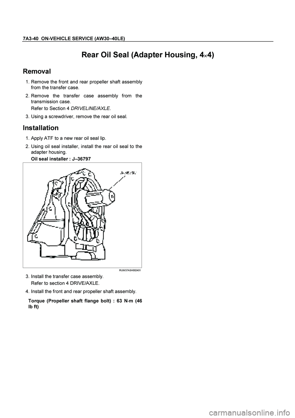
7A3-40 ON-VEHICLE SERVICE (AW30 –40LE)
Rear Oil Seal (Adapter Housing, 4�
� �
�4)
Removal
1. Remove the front and rear propeller shaft assembly
from the transfer case.
2. Remove the transfer case assembly from the transmission case.
Refer to Section 4 DRIVELINE/AXLE.
3. Using a screwdriver, remove the rear oil seal.
Installation
1. Apply ATF to a new rear oil seal lip.
2. Using oil seal installer, install the rear oil seal to the adapter housing.
Oil seal installer : J –36797
RUW37ASH002401
3. Install the transfer case assembly.
Refer to section 4 DRIVE/AXLE.
4. Install the front and rear propeller shaft assembly.
Torque (Propeller shaft flange bolt) : 63 N �
��
�
m (46
Ib ft)

10.Disconnect the solenoid wiring connectors from the
shift solenoid S1(1), S2(2), lock-up solenoid(3) and
pressure control solenoid(4).
249RY 0")
 7A3-37
Valve Body Assembly and Pressure Control Solenoid
244RY00009
Removal
Preparation:
Disconnect negative ( –) battery cable.
")