Page 2345 of 4264

3.5L ENGINE DRIVEABILITY AND EMISSIONS 6E-349
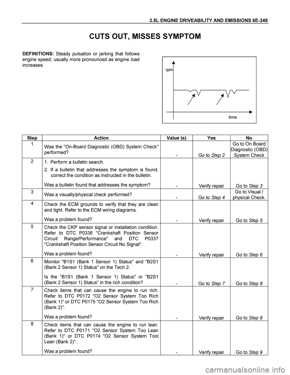
CUTS OUT, MISSES SYMPTOM
DEFINITIONS: Steady pulsation or jerking that follows
engine speed; usually more pronounced as engine load
increases.
time rpm
Step Action Value (s) Yes No
1
Was the "On-Board Diagnostic (OBD) System Check"
performed?
- Go to Step 2 Go to On Board
Diagnostic (OBD)
System Check
2
1. Perform a bulletin search.
2. If a bulletin that addresses the symptom is found,
correct the condition as instructed in the bulletin.
Was a bulletin found that addresses the symptom?
- Verify repair Go to Step 3
3
Was a visually/physical check performed?
- Go to Step 4 Go to Visual /
physical Check.
4
Check the ECM grounds to verify that they are clean
and tight. Refer to the ECM wiring diagrams.
Was a problem found?
- Verify repair Go to Step 5
5
Check the CKP sensor signal or installation condition.
Refer to DTC P0336 "Crankshaft Position Sensor
Circuit Range/Performance" and DTC P0337
"Crankshaft Position Sensor Circuit No Signal".
Was a problem found?
- Verify repair Go to Step 6
6
Monitor "B1S1 (Bank 1 Sensor 1) Status" and "B2S1
(Bank 2 Sensor 1) Status" on the Tech 2.
Is the "B1S1 (Bank 1 Sensor 1) Status" or "B2S1
(Bank 2 Sensor 1) Status" in the rich condition?
- Go to Step 7 Go to Step 8
7
Check items that can cause the engine to run rich.
Refer to DTC P0172 "O2 Sensor System Too Rich
(Bank 1)" or DTC P0175 "O2 Sensor System Too Rich
(Bank 2)".
Was a problem found?
- Verify repair Go to Step 9
8
Check items that can cause the engine to run lean.
Refer to DTC P0171 "O2 Sensor System Too Lean
(Bank 1)" or DTC P0174 "O2 Sensor System Tool
Lean (Bank 2)".
Was a problem found?
- Verify repair Go to Step 9
Page 2562 of 4264

6D3-8 STARTING AND CHARGING SYSTEM
General On-Vehicle Inspection
The operating condition of charging system is indicated by the
charge warning lamp. The warning lamp comes on when the
starter switch is turned to "ON" position. The charging system
operates normally if the lamp goes off when the engine starts.
If the warning lamp shows abnormality or if undercharged or
overcharged battery condition is suspected, perform diagnosis
by checking the charging system as follows:
1. Check visually the belt and wiring connector.
2. With the engine stopped, turn the stator switch to "ON"
position and observe the warning lamp.
If lamp does not come on:
Disconnect wiring connector from generator, and ground
the terminal "L" on connector side.
If lamp comes on:
Repair or replace the generator.
Generator
Removal
1. Disconnect battery ground cable.
2. Move drive belt tensioner to loose side using wrench then
remove drive belt.
3. Disconnect terminal "B" wiring connector and connector.
4. Remove generator assembly.
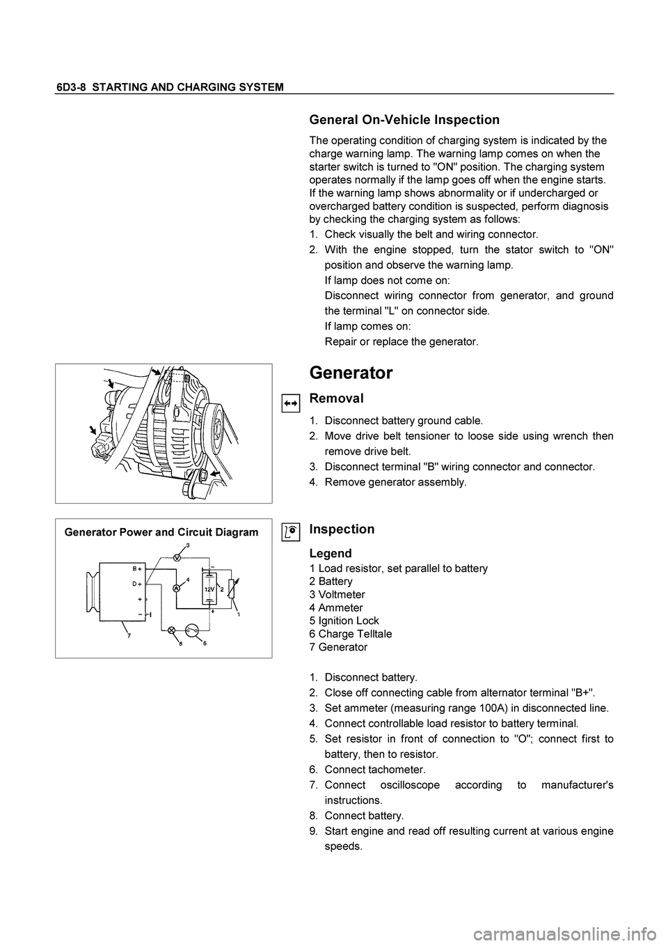
Generator Power and Circuit Diagram
Inspection
Legend
1 Load resistor, set parallel to battery
2 Battery
3 Voltmeter
4 Ammeter
5 Ignition Lock
6 Charge Telltale
7 Generator
1. Disconnect battery.
2. Close off connecting cable from alternator terminal "B+".
3. Set ammeter (measuring range 100A) in disconnected line.
4. Connect controllable load resistor to battery terminal.
5. Set resistor in front of connection to "O"; connect first to
battery, then to resistor.
6. Connect tachometer.
7. Connect oscilloscope according to manufacturer's
instructions.
8. Connect battery.
9. Start engine and read off resulting current at various engine
speeds.
Page 2563 of 4264

STARTING AND CHARGING SYSTEM 6D3-9
Generator Power
1. Adjust load resistor, if the required load currents are not
attained.
2. The shape of the voltage curves on oscilloscope curve
should be regular.
3. Test value: 5 to 7A.
4. If the required minimum current intensity is not attained, o
r
if the oscilloscope picture shows variations, the alternator
should be overhauled.
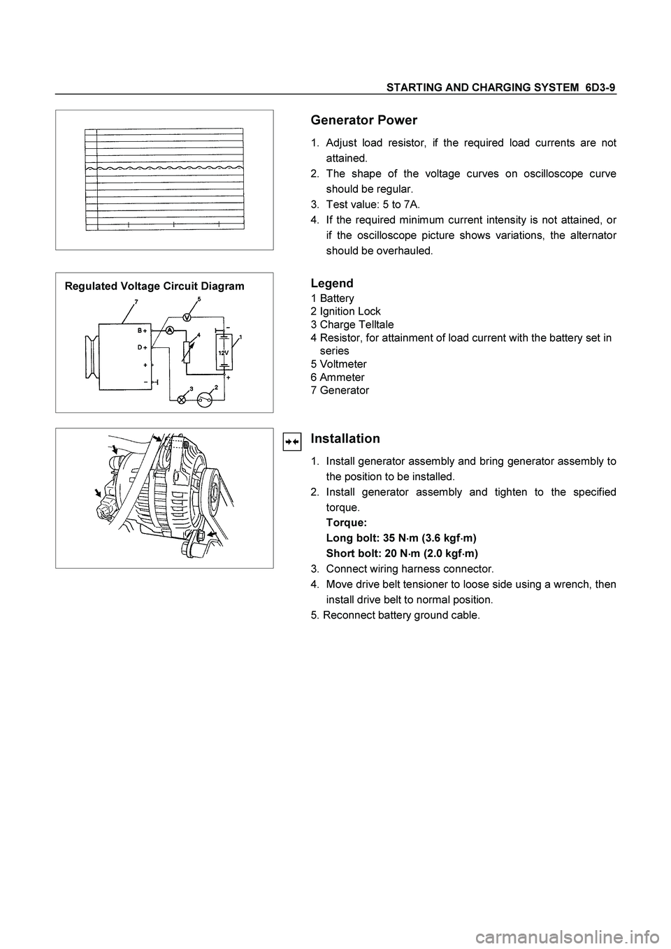
Regulated Voltage Circuit Diagram
Legend
1 Battery
2 Ignition Lock
3 Charge Telltale
4 Resistor, for attainment of load current with the battery set in
series
5 Voltmeter
6 Ammeter
7 Generator
Installation
1. Install generator assembly and bring generator assembly to
the position to be installed.
2. Install generator assembly and tighten to the specified
torque.
Torque:
Long bolt: 35 N�
�� �m (3.6 kgf�
�� �m)
Short bolt: 20 N
�
�� �m (2.0 kgf
�
�� �m)
3. Connect wiring harness connector.
4. Move drive belt tensioner to loose side using a wrench, then
install drive belt to normal position.
5. Reconnect battery ground cable.
Page 2577 of 4264

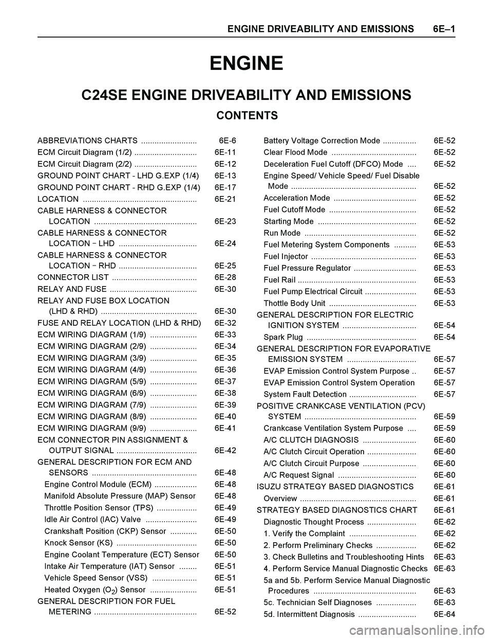
ENGINE DRIVEABILITY AND EMISSIONS 6E–1
ENGINE
CONTENTS
C24SE ENGINE DRIVEABILITY AND EMISSIONS
ABBREVIATIONS CHARTS ......................... 6E-6
ECM Circuit Diagram (1/2) ............................ 6E-11
ECM Circuit Diagram (2/2) ............................ 6E-12
GROUND POINT CHART - LHD G.EXP (1/4) 6E-13
GROUND POINT CHART - RHD G.EXP (1/4) 6E-17
LOCATION ................................................... 6E-21
CABLE HARNESS & CONNECTOR
LOCATION .............................................. 6E-23
CABLE HARNESS & CONNECTOR
LOCATION � LHD ................................... 6E-24
CABLE HARNESS & CONNECTOR
LOCATION � RHD ................................... 6E-25
CONNECTOR LIST ...................................... 6E-28
RELAY AND FUSE ....................................... 6E-30
RELAY AND FUSE BOX LOCATION
(LHD & RHD) ........................................... 6E-30
FUSE AND RELAY LOCATION (LHD & RHD) 6E-32
ECM WIRING DIAGRAM (1/9) ..................... 6E-33
ECM WIRING DIAGRAM (2/9) ..................... 6E-34
ECM WIRING DIAGRAM (3/9) ..................... 6E-35
ECM WIRING DIAGRAM (4/9) ..................... 6E-36
ECM WIRING DIAGRAM (5/9) ..................... 6E-37
ECM WIRING DIAGRAM (6/9) ..................... 6E-38
ECM WIRING DIAGRAM (7/9) ..................... 6E-39
ECM WIRING DIAGRAM (8/9) ..................... 6E-40
ECM WIRING DIAGRAM (9/9) ..................... 6E-41
ECM CONNECTOR PIN ASSIGNMENT &
OUTPUT SIGNAL .................................... 6E-42
GENERAL DESCRIPTION FOR ECM AND
SENSORS ............................................... 6E-48
Engine Control Module (ECM) ................... 6E-48
Manifold Absolute Pressure (MAP) Sensor 6E-48
Throttle Position Sensor (TPS) .................. 6E-49
Idle Air Control (IAC) Valve ....................... 6E-49
Crankshaft Position (CKP) Sensor ............ 6E-50
Knock Sensor (KS) .................................... 6E-50
Engine Coolant Temperature (ECT) Sensor 6E-50
Intake Air Temperature (IAT) Sensor ........ 6E-51
Vehicle Speed Sensor (VSS) .................... 6E-51
Heated Ox ygen (O
2) Sensor ..................... 6E-51
GENERAL DESCRIPTION FOR FUEL
METERING .............................................. 6E-52Battery Voltage Correction Mode ............... 6E-52
Clear Flood Mode ...................................... 6E-52
Deceleration Fuel Cutoff (DFCO) Mode .... 6E-52
Engine Speed/ Vehicle Speed/ Fuel Disable
Mode ........................................................ 6E-52
Acceleration Mode ..................................... 6E-52
Fuel Cutoff Mode ....................................... 6E-52
Starting Mode ............................................ 6E-52
Run Mode .................................................. 6E-52
Fuel Metering System Components .......... 6E-53
Fuel Injector ............................................... 6E-53
Fuel Pressure Regulator ............................ 6E-53
Fuel Rail ..................................................... 6E-53
Fuel Pump Electrical Circuit ....................... 6E-53
Thottle Body Unit ....................................... 6E-53
GENERAL DESCRIPTION FOR ELECTRIC
IGNITION SYSTEM ................................. 6E-54
Spark Plug ................................................. 6E-54
GENERAL DESCRIPTION FOR EVAPORATIVE
EMISSION SYSTEM ............................... 6E-57
EVAP Emission Control System Purpose .. 6E-57
EVAP Emission Control System Operation 6E-57
System Fault Detection .............................. 6E-57
POSITIVE CRANKCASE VENTILATION (PCV)
SYSTEM .................................................. 6E-59
Crankcase Ventilation System Purpose .... 6E-59
A/C CLUTCH DIAGNOSIS ........................ 6E-60
A/C Clutch Circuit Operation ...................... 6E-60
A/C Clutch Circuit Purpose ........................ 6E-60
A/C Request Signal ................................... 6E-60
ISUZU STRATEGY BASED DIAGNOSTICS 6E-61
Overview .................................................... 6E-61
STRATEGY BASED DIAGNOSTICS CHART 6E-61
Diagnostic Thought Process ...................... 6E-62
1. Verify the Complaint .............................. 6E-62
2. Perform Preliminary Checks .................. 6E-62
3. Check Bulletins and Troubleshooting Hints 6E-63
4. Perform Service Manual Diagnostic Checks 6E-63
5a and 5b. Perform Service Manual Diagnostic
Procedures .............................................. 6E-63
5c. Technician Self Diagnoses .................. 6E-63
5d. Intermittent Diagnosis .......................... 6E-64
Page 2609 of 4264
ENGINE DRIVEABILITY AND EMISSIONS 6E–33
ECM WIRING DIAGRAM (1/9)
Page 2610 of 4264
6E–34 ENGINE DRIVEABILITY AND EMISSIONS
ECM WIRING DIAGRAM (2/9)
Page 2611 of 4264
ENGINE DRIVEABILITY AND EMISSIONS 6E–35
ECM WIRING DIAGRAM (3/9)
Page 2612 of 4264
6E–36 ENGINE DRIVEABILITY AND EMISSIONS
ECM WIRING DIAGRAM (4/9)