Page 3125 of 4264

MSG MODEL 7B-7
REMOVAL AND INSTALLATION
Read this Section carefully before performing any removal and installation procedure. This Section gives you
important points as well as the order of operation. Be sure that you understand everything in this Section before
you begin.
Important Operations - Removal
Battery Cable
Disconnect the negative (-) cable from the battery terminal.
Engine Hood
Apply setting marks to the engine hood and the engine hood
hinges before removing the engine hood.
Gear Shift Lever
1. Place the gear shift lever in the neutral position.
2. Remove the gear shift lever knob.
3. Remove the front console assembly.
4. Remove the gear shift lever grommet and dust cover.
5. Remove the gear shift lever cover bolts.
6. Remove the gear shift lever.
Note:
Cover the shift lever hole to prevent the entry of foreign
material into the transmission.
Lifting the Vehicle
1. Jack up the vehicle.
2. Place chassis stands at the front and the rear of the
vehicle.
Transmission Oil Draining
1. Remove the transmission oil drain plug.
2. Replace the drain plug after draining the oil.
Page 3132 of 4264
7B-14 MSG MODEL
Exhaust Pipe
1. Install the exhaust pipe to the exhaust manifold and the
2nd exhaust pipe.
2. Install the exhaust pipe bracket to the transmission case.
Gear Shift Lever
1. Replenish the transmission case with the specified engine
oil.
Transmission Case Oil lit(US gal.)
1.55 (0.41)
2. Install the gear shift lever to the gear control box.
3. Tighten the gear shift lever cover bolts to the specified
torque.
Shift Lever Cover Bolt Torque N�
m(kgf�
m/lb�
ft)
19.6 (2.0 / 14.5)
4. Install the dust cover and the grommet.
5. Install the front console assembly.
6. Install the gear shift lever knob.
Lowering the Vehicle
1. Place a jack beneath the vehicle.
2. Raise the jack to remove the chassis stands.
3. Lower the vehicle to the ground.
Engine Hood
Align the setting marks(applied at removal)on the engine hood
and the engine hood hinges to install the engine hood.
Battery Cable
Connect the negative (-) cable to the battery terminal.
Page 3133 of 4264
MSG MODEL 7B-15
DISASSEMBLY
MAJOR COMPONENTS
RTW47BLF000301
Disassembly Steps
1. Clutch shift block and release bearing
2. Clutch shift fork
3. Speedometer sensor
4. Speedometer driven gear assembly
5. Gear control box assembly
�
6. Front cover with oil seal
�
7. Counter gear snap ring
�
8. Bearing snap ring
9. Rear cover with oil seal
10. Transmission case
11. Intermediate plate with gear assembly
Page 3134 of 4264
7B-16 MSG MODEL
Important Operations
6. Front Cover with Oil Seal
Remove the front cover with oil seal from the transmission
case.
7. Counter Gear Snap Ring
8. Bearing Snap Ring
Use pair of snap ring pliers to remove the snap ring.
Page 3149 of 4264
 Apply the engine oil to the 2nd needle bearing and the 2nd
gear.
2) Install the needle bearing and the 2nd gear to")
MSG MODEL 7B-31
Important Operations
2. Needle Bearing
3. 2nd Gear
1) Apply the engine oil to the 2nd needle bearing and the 2nd
gear.
2) Install the needle bearing and the 2nd gear to the
mainshaft.
The dog teeth of the 2nd gear must be facing the rear side
of the transmission.
5. 1st-2nd Synchronizer Assembly
1) Apply the engine oil to the clutch hub spline.
2) Install the synchronizer assembly to the mainshaft.
The outside sleeve heavy chamfering must be facing the
rear of the transmission.
1 Chamfer Angle = 30�
2 Chamfer Angle = 45�
7. Needle Bearing Collar
Use a bench press and the collar installer to install the needle
bearing collar.
Collar Installer : 5-8840-0178-0 (J-33851)
8. Needle Bearing
9. 1st Gear
1) Apply the engine oil to the 1st needle bearing and the 1st
gear.
2) Install the needle bearing and the gear to the mainshaft.
The dog teeth of the 1st gear must be facing the front side
of the transmission.
10. 1st Gear Thrust Washer
Install the thrust washer to the mainshaft.
The thrust washer oil groove must be facing the 1st gear side.
Page 3150 of 4264
 Apply the engine oil to the ball bearing inside
circumference.
2) Use a bench press and the bearing installer to install the
bearing.")
7B-32 MSG MODEL
11. Mainshaft Ball Bearing
1) Apply the engine oil to the ball bearing inside
circumference.
2) Use a bench press and the bearing installer to install the
bearing.
The bearing snap ring groove must be facing the front o
f
the transmission.
Bearing Installer : 5-8840-0015-0 (J-22912-01)
12. Needle Bearing
13. 3rd Gear
1) Apply the engine oil to the 3rd needle bearing and the 3rd
gear.
2) Install the needle bearing and the gear to the mainshaft.
The dog teeth of the 3rd gear must, be facing the front side
of the transmission.
15. 3rd-4th Synchronizer Assembly
1)
Apply the recommended lubricating oil to the clutch hub
spline.
2) Install the synchronizer assembly to the mainshaft.
The sleeve light chamfering
1 and the clutch hub heavy
boss
2 must be facing the rear of the transmission.
16. Mainshaft Snap Ring
1) Select the snap ring which will provide the minimum
clearance between the mainshaft and the snap ring.
There are four snap ring sizes available.
The snap rings are numbered to indicate their thickness.
Mainshaft and Snap Ring Clearance mm(in)
Standard
0 - 0.05 (0.002)
Snap Ring Availability mm(in)Thickness Identification Number
1.50 (0.059) 1
1.55 (0.061) 2
1.60 (0.063) 3
1.65 (0.065) 4
2) Use a pair of snap ring pliers to install the snap ring to the
mainshaft.
Page 3154 of 4264
 Apply the engine oil to the clutch hub spline.
2) Install the synchronizer assembly to the mainshaft.
The sleeve heavy chamfer
1")
7B-36 MSG MODEL
13. Rev.-5th Synchronizer Assembly
1) Apply the engine oil to the clutch hub spline.
2) Install the synchronizer assembly to the mainshaft.
The sleeve heavy chamfer
1 and the insert short side
2
must be facing to the rear side of the transmission.
14. Mainshaft Lock Nut and Washer
1) Install a new lock nut and washer to the mainshaft.
Never reinstall the used lock nut and washer.
2) Use the lock nut wrench to tighten the lock nut to the
specified torque.
Lock Nut Wrench : 5-8840-0353-0 (J-36629)
Lock Nut Torque N�m(kgf�m/lb�ft)
107.8 (11 / 79.6)
22. Counter Reverse Gear Nut and Washer
Tighten the counter gear lock nut to the specified torque.
Reverse Gear Nut Torque N�
m(kgf�
m/lb�
ft)
107.8 (11 / 79.6)
18. Thrust Washer and Lock Ball
23. Thrust Washer Thrust Ring
24. Thrust Ring Snap ring
1) Install the thrust washer with lock ball together with the
thrust ring to the mainshaft.
2) Use a pair of snap ring pliers to install the snap ring.
3) Use a thickness gauge to measure the clearance between
the 5th gear and the thrust washer.
5th Gear and Thrust Washer Clearance mm(in)
Standard
0.1 - 0.3 (0.004 - 0.012)
If required, replace the existing thrust washer with a new
thrust washer to bring the clearance to specification.
Page 3158 of 4264
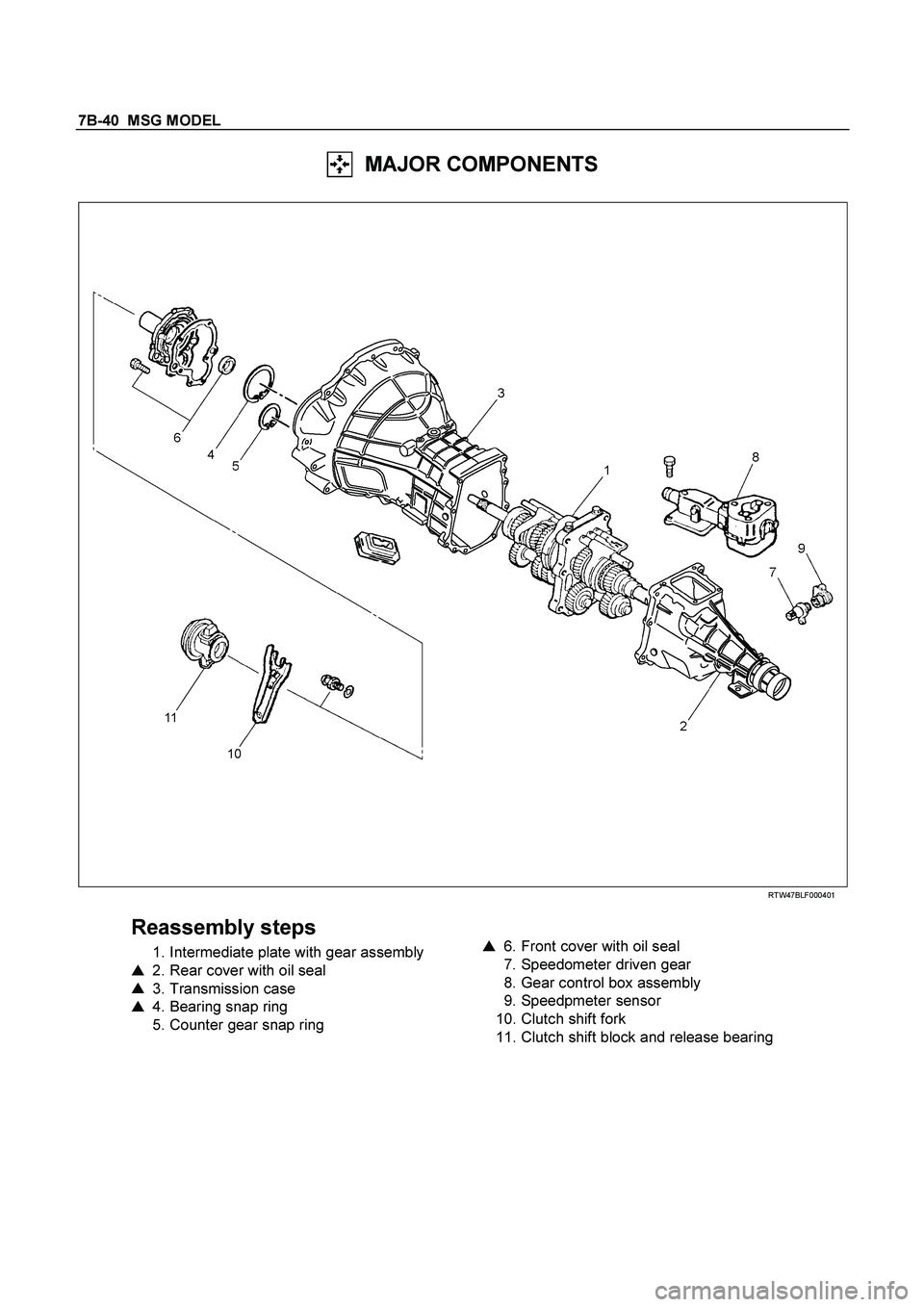
7B-40 MSG MODEL
MAJOR COMPONENTS
RTW47BLF000401
Reassembly steps
1. Intermediate plate with gear assembly
�
2. Rear cover with oil seal
�
3. Transmission case
�
4. Bearing snap ring
5. Counter gear snap ring
�
6. Front cover with oil seal
7. Speedometer driven gear
8. Gear control box assembly
9. Speedpmeter sensor
10. Clutch shift fork
11. Clutch shift block and release bearing