Page 4105 of 4264
DIAGNOSIS (JR405E) 7A2-113
Step Action Yes No
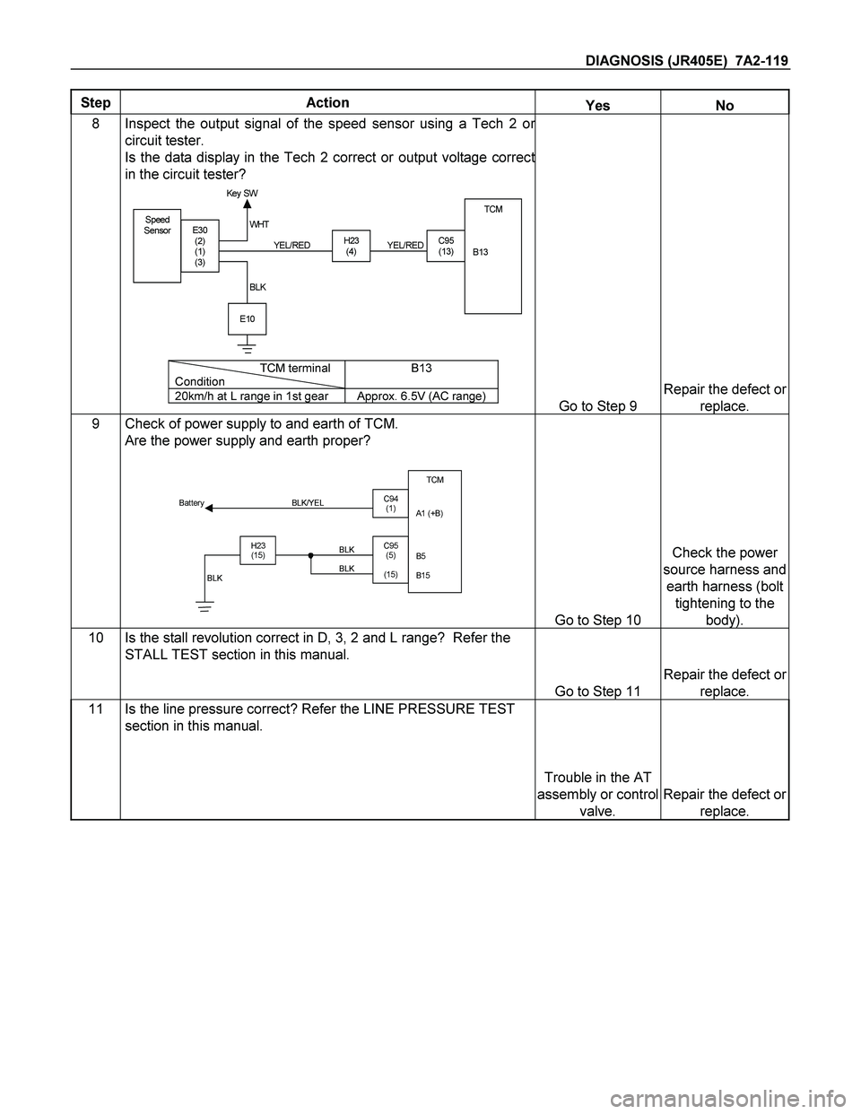
6 Inspect the output voltage and throttle opening signal of the
throttle position sensor using a Tech 2 or circuit tester.
Is a voltage value in proportion to the throttle opening output?
TPSTCM
A16
C56
(28)C94
(16) RED/ WHT
C56
(49)
(38)
(57)
(69)ECM
A47 (GND)
A35 (Out put )
A26
A55 (+5V)
A69 (I dl e SW)
Go to Step 7
Repair the defect or
replace.
8 Check of power supply to and earth of TCM.
Are the power supply and earth proper?
TCM
A1 (+B)
B5
B15
H23
(15)C95
(5)
(15) BLK/YEL
BLK BLK Battery
C94
(1)
BLK
Go to Step 9
Check the power
source harness and
earth harness (bolt
tightening to the
body).
9 Is the stall revolution correct in D, 3, 2 and L range? Refer the
STALL TEST section in this manual.
Go to Step 10
Repair the defect or
replace.
10 Is the line pressure correct? Refer the LINE PRESSURE TEST
section in this manual.
Trouble in the AT
assembly or control
valve.
Repair the defect or
replace.
Page 4111 of 4264

DIAGNOSIS (JR405E) 7A2-119
Step Action Yes No
8 Inspect the output signal of the speed sensor using a Tech 2 or
circuit tester.
Is the data display in the Tech 2 correct or output voltage correct
in the circuit tester?
Speed
SensorTCM
B13
H23
(4)C95
(13)E30
(2)
(1)
(3)
E10
Key SW
YEL/RED WHT
BLKYEL/RED
TCM terminal
ConditionB13
20km/h at L range in 1st gear Approx. 6.5V (AC range)Go to Step 9
Repair the defect or
replace.
9 Check of power supply to and earth of TCM.
Are the power supply and earth proper?
TCM
A1 (+B)
B5
B15
H23
(15)C95
(5)
(15) BLK/YEL
BLK BLK Battery
C94
(1)
BLK
Go to Step 10
Check the power
source harness and
earth harness (bolt
tightening to the
body).
10 Is the stall revolution correct in D, 3, 2 and L range? Refer the
STALL TEST section in this manual.
Go to Step 11
Repair the defect or
replace.
11 Is the line pressure correct? Refer the LINE PRESSURE TEST
section in this manual.
Trouble in the AT
assembly or control
valve.
Repair the defect or
replace.
Page 4115 of 4264
DIAGNOSIS (JR405E) 7A2-123
Step Action Yes No
6 Check of power supply to and earth of TCM.
Are the power supply and earth proper?
TCM
A1 (+B)
B5
B15
H23
(15)C95
(5)
(15) BLK/YEL
BLK BLK Battery
C94
(1)
BLK
Go to Step 7
Check the power
source harness and
earth harness (bolt
tightening to the
body).
7 Inspection of speed sensor and turbine sensor
Have the speed sensor and turbine sensor failed at the same
time? (No DTC is stored at the time of trouble) Repair the defect or
replace. Go to Step 8
8 Is the stall revolution correct in D, 3, 2 and L range? Refer the
STALL TEST section in this manual.
Go to Step 9
Repair the defect or
replace.
9 Is the line pressure correct? Refer the LINE PRESSURE TEST
section in this manual. Trouble in the AT
assembly or control
valve.
Repair the defect or
replace.
Page 4121 of 4264
DIAGNOSIS (JR405E) 7A2-129
Step Action Yes No
6 Inspect the output voltage and throttle opening signal of the
throttle position sensor using a Tech 2 or circuit tester.
Is a voltage value in proportion to the throttle opening output?
TPSTCM
A16
C56
(28)C94
(16) RED/ WHT
C56
(49)
(38)
(57)
(69)ECM
A47 (GND)
A35 (Out put )
A26
A55 (+5V)
A69 (I dl e SW)
Go to Step 7
Repair the defect or
replace.
7 Check of power supply to and earth of TCM.
Are the power supply and earth proper?
TCM
A1 (+B)
B5
B15
H23
(15)C95
(5)
(15) BLK/YEL
BLK BLK Battery
C94
(1)
BLK
Go to Step 8
Check the power
source harness and
earth harness (bolt
tightening to the
body).
8 Is the stall revolution correct in D, 3, 2 and L range? Refer the
STALL TEST section in this manual.
Go to Step 6
Repair the defect or
replace.
9 Is the line pressure correct? Refer the LINE PRESSURE TEST
section in this manual. Trouble in the AT
assembly or control
valve.
Repair the defect or
replace.
Page 4146 of 4264

7A2-154 DIAGNOSIS (JR405E)
TCM VOLTAGE CHECK
TCM voltage check is done to check for transmission and TCM
problems which cannot be detected by self-diagnosis.
Additionally, it severs as a back-up check for self-diagnosis.
Measure the voltage drop and make a continuity test for each of
sensors, solenoids and switches.
If the voltage is within the specified range and continuity exists,
that particular area of the TCM and transmission assembly is
normal.
If voltage deviation or lack of continuity is discovered, disconnect
the applicable parts and check of them individually.
Inspection Tool
Use a circuit tester and an oscilloscope to measure voltage and
circuit continuity.
Insert the test probes from the connector wiring side. TCM
terminals are extremely small.
Wrap a piece of thin wire around the probe of tester.
This will make measurement easier.
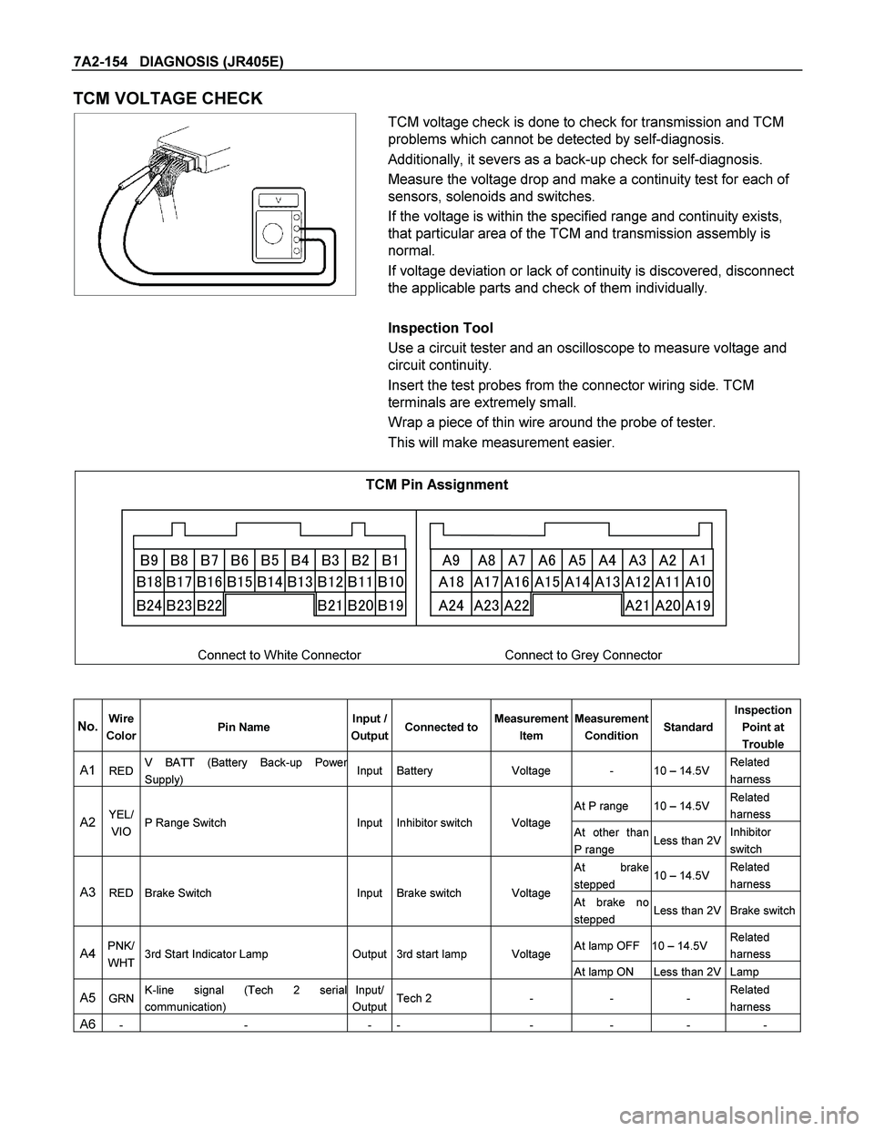
TCM Pin Assignment
��� ��� ��� ��� ��� ��� � � �
�� �� �� �� �� �� ��� � � �
� ��
���������������������� ���
���� ��
��� ��� ��� ��� ��� �� ���
�������
�
���
��
�����
���
��� �
��
�
��
���
����
Connect to White Connector Connect to Grey Connector
No. Wire
Color Pin Name Input /
OutputConnected toMeasurement
Item Measurement
Condition StandardInspection
Point at
Trouble
A1 RED V BATT (Battery Back-up Power
Supply) Input Battery Voltage - 10 – 14.5V Related
harness
At P range 10 – 14.5V Related
harness
A2 YEL/
VIO P Range Switch Input Inhibitor switch Voltage
At other than
P range Less than 2VInhibitor
switch
At brake
stepped 10 – 14.5V Related
harness
A3 RED Brake Switch Input Brake switch Voltage At brake no
stepped Less than 2V Brake switch
At lamp OFF 10 – 14.5V Related
harness A4 PNK/
WHT 3rd Start Indicator Lamp Output 3rd start lamp Voltage
At lamp ON Less than 2V Lamp
A5 GRN K-line signal (Tech 2 serial
communication) Input/
OutputTech 2 - - - Related
harness
A6 - - - - - - - -
Page 4156 of 4264
7A3-4 ON-VEHICLE SERVICE (JR405E)
TRANSMISSION CONTROL MODULE (TCM)
RTW37ALF001901
Remove and Disconnect
1. Disconnect the negative battery cable.
2. Remove the connectors.
3. Remove the fixing nuts and remove the TCM (1)
from the bracket.
Note:
The TCM is fitted under instrument panel of the driver’s
compartment by means of three stud bolts.
Install or Connect
Follow the removal steps in the reverse order. Be
absolutely sure that the connectors are securely
fastened.
AT CONT
Page 4158 of 4264

7A3-6 ON-VEHICLE SERVICE (JR405E)
INHIBITOR SWITCH
The inhibitor switch is attached to the right side of the
transmission.
Inspect
1. Block the wheels.
2. Disconnect the negative battery cable.
3. Disconnect the harness connectors.
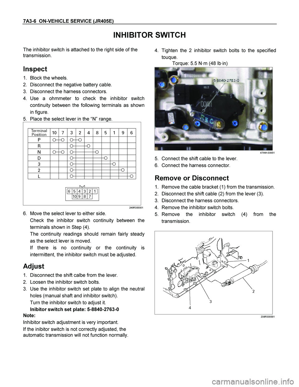
4. Use a ohmmeter to check the inhibitor switch
continuity between the following terminals as shown
in figure.
5. Place the select lever in the “N” range.
249R300001
6. Move the select lever to either side.
Check the inhibitor switch continuity between the
terminals shown in Step (4).
The continuity readings should remain fairly steady
as the select lever is moved.
If there is no continuity or the continuity is
intermittent, the inhibitor switch must be adjusted.
Adjust
1. Disconnect the shift calbe from the lever.
2. Loosen the inhibitor switch bolts.
3. Use the inhibitor switch set plate to align the neutral
holes (manual shaft and inhibitor switch).
Turn the inhibitor switch to adjust it.
Inibitor switch set plate: 5-8840-2763-0
Note:
Inhibitor switch adjustment is very important.
If the inibitor switch is not correctly adjusted, the
automatic transmission will not function normally.
4. Tighten the 2 inhibitor switch bolts to the specified
touque.
Torque: 5.5 N·m (48 lb·in)
47INH-SW01
5. Connect the shift cable to the lever.
6. Connect the harness connector.
Remove or Disconnect
1. Remove the cable bracket (1) from the transmission.
2. Disconnect the shift cable (2) from the lever (3).
3. Disconnect the harness connectors.
4. Remove the inhibitor switch bolts.
5. Remove the inhibitor switch (4) from the
transmission.
238R300001
Page 4159 of 4264
ON-VEHICLE SERVICE (JR405E) 7A3-7
Install or Connect
1. Install the inhibitor switch (4) to the transmission.
Temporarily tighten the inhibitor switch bolts.
2. Move the manual shaft select lever to the “N” range.
249R300002
3. Use the inhibitor switch set plate to align the neutral
holes (manual shaft and inhibitor switch).
Turn the inhibitor switch to adjust it.
Inhibitor switch set plate: 5-8840-2763-0
Note:
Inhibitor switch adjustment is very important.
If the inhibitor switch is not correctly adjusted, the
automatic transmission will not function normally.
4. Tighten the 2 inhibitor switch bolts to the specified
torque.
Torque: 5.5 N·m (48 lb·in)
47INH-SW01
5. Install the cable bracket (1) to the transmission.
6. Connect the shift cable (2) to the lever (3).
7. Connect the harness connector.
8. Connect the negative battery cable.
9. Remove the wheel blocks.