Page 3003 of 4264

�
�� �
In order to obtain maximum performance and longest service life from your ISUZU vehicles, it is very important")
MAINTENANCE AND LUBRICATION 0B-15
RECOMMENDED FLUIDS AND LUBRICANTS (For EUROPE)
�
�� �
In order to obtain maximum performance and longest service life from your ISUZU vehicles, it is very important to
select and use correctly best lubricants and diesel fuels.
When lubricating, be sure to use ISUZU genuine lubricants or recommended lubricants listed below, according to
the maintenance schedule for each vehicle model.
LUBRICATION/FLUID GRADE
API ACEA OTHER
Diesel engine crankcase B2/B3
E2/E3
Manual transmission
Transfer case B2/B3
E2/E3
Differential
Shift on the fly system
(GL-5 only)
GL-5 BESCO GEAR OIL SH (80W-90, 90, 140) (ISUZU GENUINE)
BESCO SHIFT ON THE FLY (75W-90) (ISUZU GENUINE)
GEAR OIL GX (85W-90) (EXXON / ESSO)
MOBILUBE HD (80W-90, 85W-140) (MOBIL)
THURBAN GL-5 EP (80W-90, 85W-140) (CALTEX)
SPIRAX HD (90, 140) (SHELL)
TRANSELF TYPE B (80W-90, 85W-140) (ELF)
TRANSMISSION TM (80W-90, 85W-140) (TOTAL)
Differential
(Limited Slip Differential)
GL-5 * Limited
Slip
Differential
Gear
Lubricant
BESCO GEAR OIL LSD (140) (ISUZU GENUINE)
GEAR OIL LSA (90) (EXXON/ESSO)
MOBILUBE HD LS (80W-90) (MOBIL)
GEAR OIL LSD (90) (CALTEX)
TRANSELF TYPE BLS (90) (SHELL)
TRANSMISSION DA (85W-90) (ELF)
HYPOY LS (90) (TOTAL)
Automatic transmission
Power steering
DEXRON II, III
Propeller shaft sliding yoke
Universal joint
(General purpose grease in
Molybdenum) NLGI #2 or #3
multi purpose type grease
containing molybdenum disulfide
Engine cooling system Good quality ethylene glycol antifreeze or GM spec.
6033-M or equivalent
* If GL-5 Limited Slip Differential Lubricant is not available, use GL-5 Lubricant together with Limited Slip Differential Lubricant additive (Parts No. 8-01052-358-0) or
equivalent.
FLUID TYPE
Clutch and brake fluid reservoir Besco brake fluid (For light duty)
Hydraulic brake fluid SAE J1703
FMVSS 116 DOT.3 grade
DIESEL FUEL/APPLICABLE STANDARD
JIS (JAPANESE INDUSTRIAL STANDARD)
DIN (DEUTSCHE INDUSTRIE NORMEN)
SAE (SOCIETY OF AUTOMOTIVE ENGINEERS)
BS (BRITISH STANDARD) Based on K2204 GAS OIL
Based on EN590: 1997L
Based on SAE J-313C
Based on BS EN590: 1997
NOTE:
Use the applicable standard or equivalent for diesel fuels.
�
�
�
Page 3004 of 4264
0B-16 MAINTENANCE AND LUBRICATION
OIL VISCOSITY CHART
Lubricants should be carefully selected according to the lubrication chart. It is also important to select viscosity of
lubricants according to the ambient temperature by referring to the following table.
OIL VISCOSITY CHART FOR DIESEL ENGINE
APPLY DIESEL ENGINE OIL
(Single grade)VISCOSITY GRADE - AMBIENT TEMPERATURE
-25 C -15 C -10 C
32 F 5 F -13 F 77 F
0 C 30 C
86 F
*Not recomended for sustained high speed driving.
SAE 30
SAE 10W-30
SAE 15W-40, 20W-40, 20W-50
SAE 5W-30
SAE 20, 20W
SAE 10W
SAE 40, 50
25 C
15 C
(Multi grade)
*
60 F 14 F
ED-03 �
�
�
�
OIL VISCOSITY CHART FOR GASOLINE ENGINE
APPLY GASOLINE ENGINE OIL
(Malti grade) �
�
Page 3159 of 4264

Align the pins at the lower side of the rear cover with the
holes in the lower side of the intermediate pl")
MSG MODEL 7B-41
RTW47BSH000201
Important Operations
2. Rear Cover with Oil Seal
1)
Align the pins at the lower side of the rear cover with the
holes in the lower side of the intermediate plate.
2)
Apply recommended liquid gasket or its equivalent to the
rear cover fitting surfaces.
3) Install the rear cover to the intermediate plate.
4) Tighten the rear cover bolts to the specified torque.
Rear Cover Bolt Torque N�
m(kgf�
m/lb�
ft)
37.2 (3.8 / 27.5)
Note:
Take care not to twist or puncture the oil seal during the
installation procedure.
RTW47BSH000301
3. Transmission Case
4. Bearing Snap Ring
1) Apply the engine oil to the transmission case top gear shaft
ball bearing fitting faces.
2)
Apply recommended liquid gasket or its equivalent to the
transmission case fitting surfaces.
3) Install the transmission case to the intermediate plate.
4) Pull the top gear shaft from the transmission case until the
ball bearing snap ring grove protrudes from the
transmission case front cover fitting faces.
5) Use a pair of snap ring pliers to install the snap ring to the
ball bearing.
6. Front Cover with Oil Seal
1) Clean and apply recommended liquid gasket or its
equivalent to the through bolt threads.
2) Install the new gasket and tighten the new cover bolt to the
specified torgue.
Front Cover Bolt Torgue N�
m(kgf�
m/lb.ft)
24.5 (2.5 / 18.1)
RTW47BSH000101
10. Shift Fork
Apply molybdenum disulfide type grease to the areas as
shown in the figure and install shift fork (Diesel engine).
Page 3171 of 4264
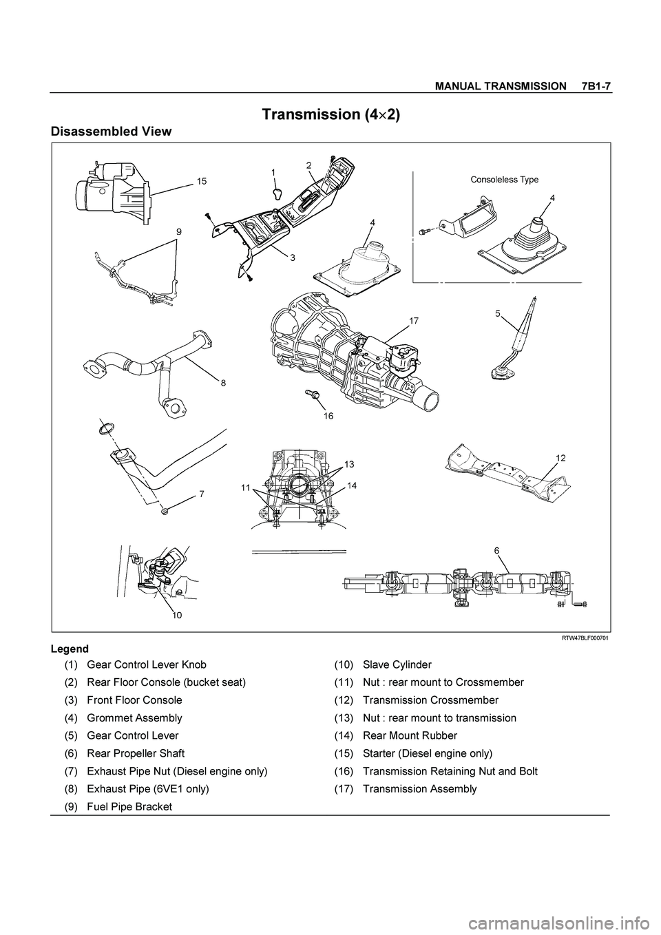
MANUAL TRANSMISSION 7B1-7
Transmission (4�
�� �
2)
Disassembled View
RTW47BLF000701
Legend
(1) Gear Control Lever Knob (10) Slave Cylinder
(2) Rear Floor Console (bucket seat) (11) Nut : rear mount to Crossmember
(3) Front Floor Console (12) Transmission Crossmember
(4) Grommet Assembly (13) Nut : rear mount to transmission
(5) Gear Control Lever (14) Rear Mount Rubber
(6) Rear Propeller Shaft (15) Starter (Diesel engine only)
(7) Exhaust Pipe Nut (Diesel engine only) (16) Transmission Retaining Nut and Bolt
(8) Exhaust Pipe (6VE1 only) (17) Transmission Assembly
(9) Fuel Pipe Bracket
Page 3173 of 4264
MANUAL TRANSMISSION 7B1-9
6. Remove gear control lever (5).
7. Raise and support vehicle with suitable stands.
8. Remove rear propeller shaft (6).
NOTE: Apply alignment marks on the flange at the
differential side.
401RS023
9. Loosen the front exhaust pipe fixing nuts (7) at the
engine side but not remove them. (Diesel engine
only)
150R300003
10. Remove the exhaust pipe (8). (6VE1 only)
RTW37ASH0001
11. Disconnect harness connectors and clips on the
transmission.
� Neutral Switch
�
Back up Switch
� Car Speed Sensor
12. Remove the fuel pipe bracket (9) with pipes from the
transmission (17).
Diesel engine
220R300012
Legend
(1) Bolt
(2) Nut
(3) Fuel Pipe Assembly
Page 3174 of 4264
7B1-10 MANUAL TRANSMISSION
6VE1, C24NE
Scan-1
13. Remove slave cylinder (10) and put aside it.
Diesel engine
220LV019
6VE1
206RW002
14. Support transmission with a transmission jack.
220RS001
15. Remove engine rear mount nuts (11) fixing on cross
member from transmission crossmember (12).
16. Remove engine rear mount nuts (13) fixing on
transmission.
220R300029
Legend
(1) Transmission
(2) Nut : rear mount to transmission
(3) Rear Mount Rubber
(4) Nut : rear mount to crossmember
(5) Transmission Crossmember
Page 3175 of 4264
MANUAL TRANSMISSION 7B1-11
17. Remove the middle part of transmission
crossmember (12) by removing four fixing bolts and
nuts.
501R300008
18. Take out the rear mount rubber (14).
19. Remove starter (15) (Diesel engine only).
060L100070
20. Use the clutch release bearing remover 5-8840-
2291-0 (J-39207) to disconnect the clutch release
bearing from the clutch pressure plate. (6VE1 only)
220RW109
Release bearing disconnection
1. Pull the shift fork toward the transmission to
press the clutch release bearing against the
clutch.
2. Insert the clutch release bearing remover
between the wedge collar and the release
bearing.
3. Turn the remover to separate the release
bearing.
Page 3177 of 4264
MANUAL TRANSMISSION 7B1-13
4. Install the transmission assembly (17) to the engine.
Tighten the transmission nuts and bolts (16) as
shown in the figure.
Diesel engine
RTW37BLF000901

.
7. Raise and support vehicle with suitable stands.
8. Remove rear propeller shaft (6).
NOTE: Apply alignment marks on the fla")
 and put aside it.
Diesel engine
220LV019
6VE1
206RW002
14. Support transmission with a transmission ja")
 by removing four fixing bolts and
nuts.
501R300008
18. Take out the rear mount rubber (14).
19. Remov")
 to the engine.
Tighten the transmission nuts and bolts (16) as
shown in the figure.
Diesel engine
RTW37BLF000901")