2004 ISUZU TF SERIES oil
[x] Cancel search: oilPage 2023 of 4264
3.5L ENGINE DRIVEABILITY AND EMISSIONS 6E-27
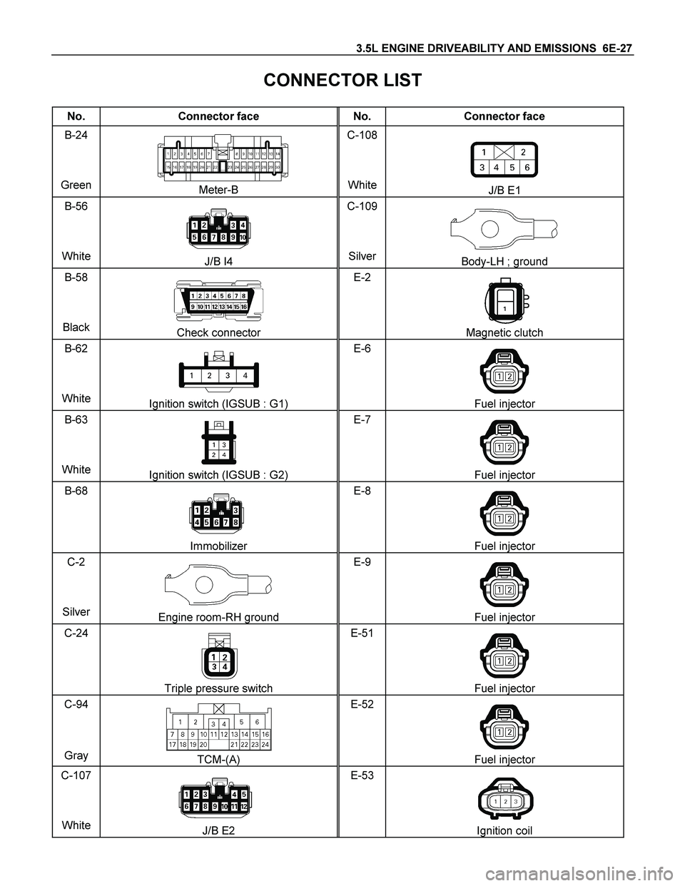
CONNECTOR LIST
No. Connector face No. Connector face
B-24
Green
Meter-B C-108
WhiteJ/B E1
B-56
White
J/B I4 C-109
SilverBody-LH ; ground
B-58
Black
Check connector E-2
Magnetic clutch
B-62
White
Ignition switch (IGSUB : G1) E-6
Fuel injector
B-63
White
Ignition switch (IGSUB : G2) E-7
Fuel injector
B-68
Immobilizer E-8
Fuel injector
C-2
Silver
Engine room-RH ground E-9
Fuel injector
C-24
Triple pressure switch E-51
Fuel injector
C-94
Gray TCM-(A) E-52
Fuel injector
C-107
White
J/B E2 E-53
Ignition coil
Page 2024 of 4264
6E-28 3.5L ENGINE DRIVEABILITY AND EMISSIONS
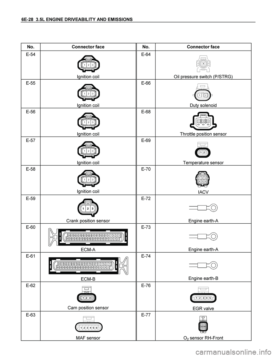
No. Connector face No. Connector face
E-54
Ignition coil E-64
Oil pressure switch (P/STRG)
E-55
Ignition coil E-66
Duty solenoid
E-56
Ignition coil E-68
Throttle position sensor
E-57
Ignition coil E-69
Temperature sensor
E-58
Ignition coil E-70
IACV
E-59
Crank position sensor E-72
Engine earth-A
E-60
ECM-A E-73
Engine earth-A
E-61
ECM-B E-74
Engine earth-B
E-62
Cam position sensor E-76
EGR valve
E-63
MAF sensor E-77
O2 sensor RH-Front
Page 2040 of 4264
6E-44 3.5L ENGINE DRIVEABILITY AND EMISSIONS
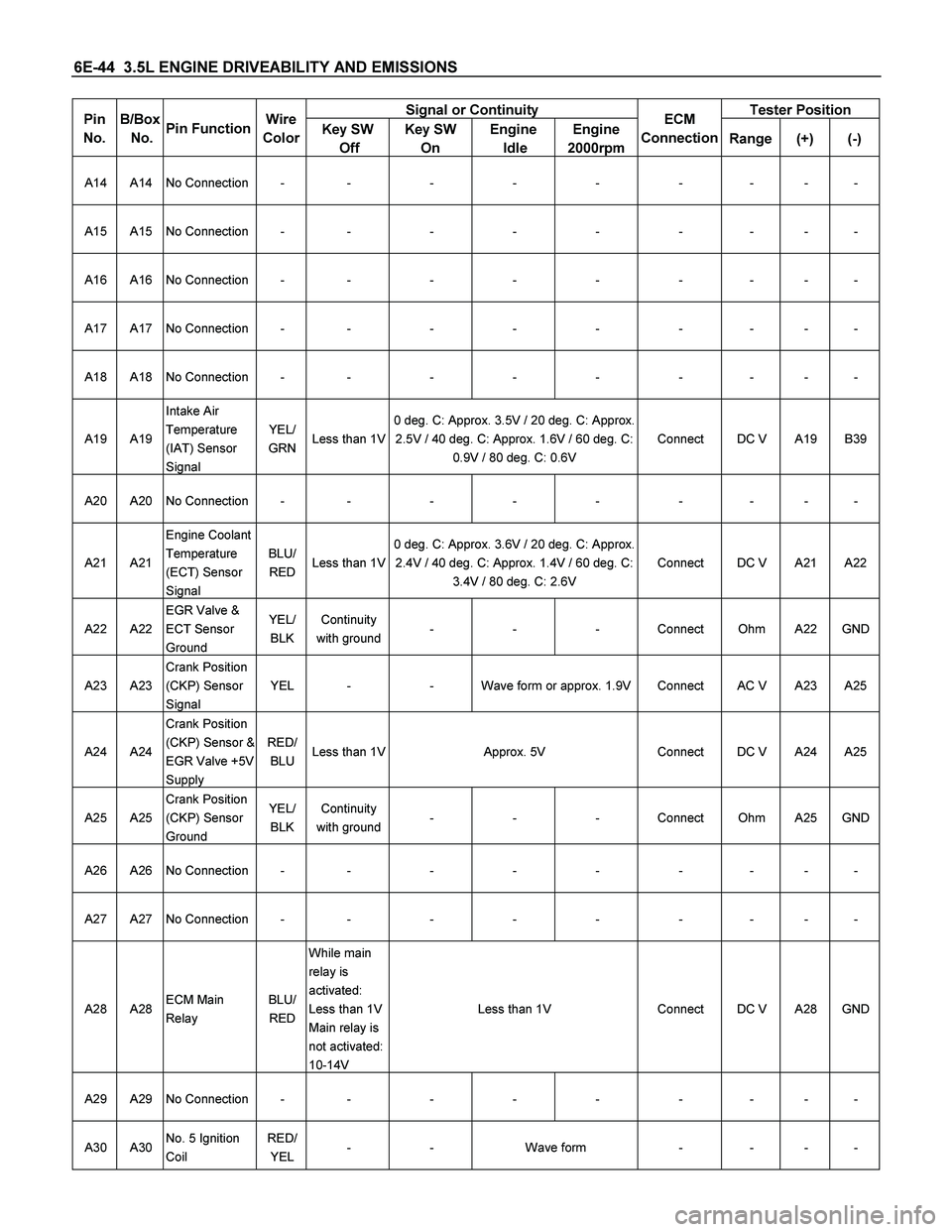
Signal or Continuity Tester Position Pin
No.
B/Box
No.
Pin Function Wire
Color
Key SW
Off Key SW
On Engine
Idle Engine
2000rpmECM
Connection Range(+) (-)
A14 A14 No Connection - - - - - - - - -
A15 A15 No Connection - - - - - - - - -
A16 A16 No Connection - - - - - - - - -
A17 A17 No Connection - - - - - - - - -
A18 A18 No Connection - - - - - - - - -
A19 A19 Intake Air
Temperature
(IAT) Sensor
Signal YEL/
GRN Less than 1V0 deg. C: Approx. 3.5V / 20 deg. C: Approx.
2.5V / 40 deg. C: Approx. 1.6V / 60 deg. C:
0.9V / 80 deg. C: 0.6V Connect DC V A19 B39
A20 A20 No Connection - - - - - - - - -
A21 A21 Engine Coolant
Temperature
(ECT) Sensor
Signal BLU/
RED Less than 1V0 deg. C: Approx. 3.6V / 20 deg. C: Approx.
2.4V / 40 deg. C: Approx. 1.4V / 60 deg. C:
3.4V / 80 deg. C: 2.6V Connect DC V A21 A22
A22 A22 EGR Valve &
ECT Sensor
Ground YEL/
BLK Continuity
with ground - - - Connect Ohm A22 GND
A23 A23 Crank Position
(CKP) Sensor
Signal YEL - - Wave form or approx. 1.9V Connect AC V A23 A25
A24 A24 Crank Position
(CKP) Sensor &
EGR Valve +5V
Supply RED/
BLU Less than 1V Approx. 5V Connect DC V A24 A25
A25 A25 Crank Position
(CKP) Sensor
Ground YEL/
BLK Continuity
with ground - - - Connect Ohm A25 GND
A26 A26 No Connection - - - - - - - - -
A27 A27 No Connection - - - - - - - - -
A28 A28 ECM Main
Relay BLU/
RED While main
relay is
activated:
Less than 1V
Main relay is
not activated:
10-14V Less than 1V Connect DC V A28 GND
A29 A29 No Connection - - - - - - - - -
A30 A30 No. 5 Ignition
Coil RED/
YEL - - Wave form - - - -
Page 2041 of 4264
3.5L ENGINE DRIVEABILITY AND EMISSIONS 6E-45
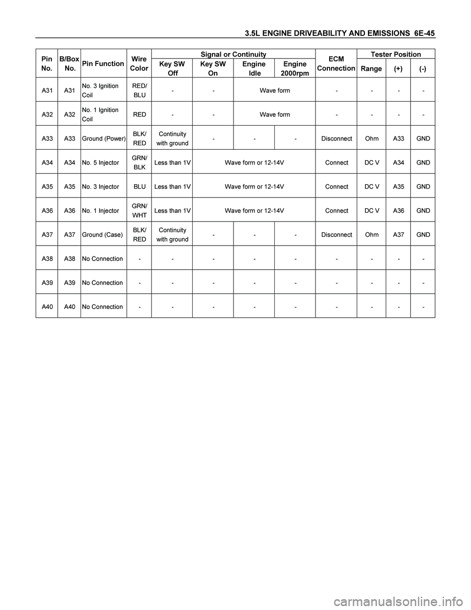
Signal or Continuity Tester Position Pin
No.
B/Box
No.
Pin Function Wire
Color
Key SW
Off Key SW
On Engine
Idle Engine
2000rpmECM
Connection Range(+) (-)
A31 A31 No. 3 Ignition
Coil RED/
BLU - - Wave form - - - -
A32 A32 No. 1 Ignition
Coil RED - - Wave form - - - -
A33 A33 Ground (Power) BLK/
RED Continuity
with ground - - - Disconnect Ohm A33 GND
A34 A34 No. 5 Injector GRN/
BLK Less than 1V Wave form or 12-14V Connect DC V A34 GND
A35 A35 No. 3 Injector BLU Less than 1V Wave form or 12-14V Connect DC V A35 GND
A36 A36 No. 1 Injector GRN/
WHT Less than 1V Wave form or 12-14V Connect DC V A36 GND
A37 A37 Ground (Case) BLK/
RED Continuity
with ground - - - Disconnect Ohm A37 GND
A38 A38 No Connection - - - - - - - - -
A39 A39 No Connection - - - - - - - - -
A40 A40 No Connection - - - - - - - - -
Page 2042 of 4264
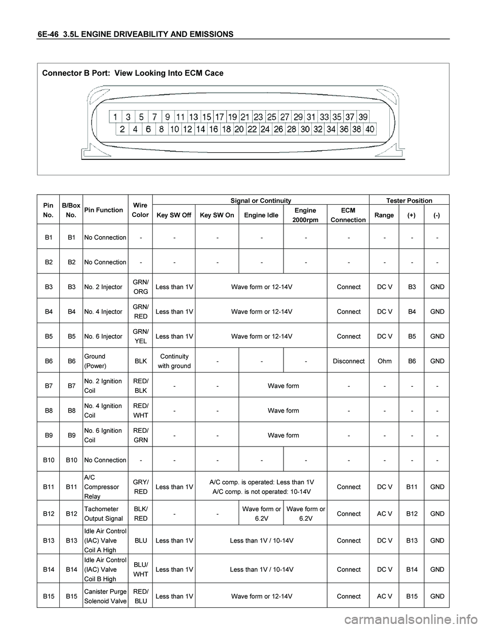
6E-46 3.5L ENGINE DRIVEABILITY AND EMISSIONS
Connector B Port: View Looking Into ECM Cace
Signal or Continuity Tester Position Pin
No. B/Box
No. Pin Function Wire
Color
Key SW Off Key SW On Engine IdleEngine
2000rpm ECM
Connection Range (+) (-)
B1 B1 No Connection - - - - - - - - -
B2 B2 No Connection - - - - - - - - -
B3 B3 No. 2 Injector GRN/
ORG Less than 1V Wave form or 12-14V Connect DC V B3 GND
B4 B4 No. 4 Injector GRN/
RED Less than 1V Wave form or 12-14V Connect DC V B4 GND
B5 B5 No. 6 Injector GRN/
YELLess than 1V Wave form or 12-14V Connect DC V B5 GND
B6 B6 Ground
(Power) BLK Continuity
with ground - - - Disconnect Ohm B6 GND
B7 B7 No. 2 Ignition
Coil RED/
BLK- - Wave form - - - -
B8 B8 No. 4 Ignition
Coil RED/
WHT - - Wave form - - - -
B9 B9 No. 6 Ignition
Coil RED/
GRN - - Wave form - - - -
B10 B10 No Connection - - - - - - - - -
B11 B11 A/C
Compressor
Relay GRY/
RED Less than 1V A/C comp. is operated: Less than 1V
A/C comp. is not operated: 10-14V Connect DC V B11 GND
B12 B12 Tachometer
Output Signal BLK/
RED - - Wave form or
6.2V Wave form or
6.2V Connect AC V B12 GND
B13 B13 Idle Air Control
(IAC) Valve
Coil A High BLU Less than 1V Less than 1V / 10-14V Connect DC V B13 GND
B14 B14 Idle Air Control
(IAC) Valve
Coil B High BLU/
WHT Less than 1V Less than 1V / 10-14V Connect DC V B14 GND
B15 B15 Canister Purge
Solenoid Valve RED/
BLULess than 1V Wave form or 12-14V Connect AC V B15 GND
Page 2043 of 4264

3.5L ENGINE DRIVEABILITY AND EMISSIONS 6E-47
Signal or Continuity Tester Position Pin
No. B/Box
No. Pin Function Wire
Color
Key SW Off Key SW On Engine IdleEngine
2000rpm ECM
Connection Range (+) (-)
B16 B16 Idle Air Control
(IAC) Valve
Coil A Low BLU/
RED Less than 1V Less than 1V / 10-14V Connect DC V B16 GND
B17 B17 Idle Air Control
(IAC) Valve
Coil B Low BLU/
BLKLess than 1V Less than 1V / 10-14V Connect DC V B17 GND
B18 B18 Check Engine
Lamp
(Immobilizer
Control Unit
Terminal B7) BRN/
YELLess than 1V Less than 1VLamp is turned on:
Less than 1V
Lamp is turned off: 10-14VConnect DC V B18 GND
B19 B19 Fuel Pump
Relay GRN/
WHT Less than 1V While relay is
activated:
10-14V
Relay is not
activated:
Less than 1V10-14V Connect DC V B19 GND
B20 B20 Mass Air Flow
(MAF) Sensor BLK/
YELLess than 1V Approx. 0.47VApprox. 1.5V
at 750 rpmApprox. 2V Connect DC V B20 GND
B21 B21 Bank 1 Oxygen
Sensor Signal PNK Less than 1V Approx. 0.4V 0.1 - 0.9V Connect DC V B21 B22
B22 B22 Bank 1 Oxygen
Sensor Ground BLU/
YELContinuity
with ground - - - Connect Ohm B22 GND
B23 B23 Bank 2 Oxygen
Sensor Signal RED Less than 1V Approx. 0.4V 0.1 - 0.9V Connect DC V B23 B24
B24 B24 Bank 2 Oxygen
Sensor Ground BLU/
BLKContinuity
with ground - - - Connect Ohm B24 GND
B25 B25 To Data Link
Connector
No.6 BLK/
GRN - - - - - - - -
B26 B26 Throttle
Position
Sensor (TPS)
Signal BLU Less than 1V Approx. 0.5V Approx. 0.6V Connect DC V B26 B39
B27 B27 TPS & Cam
Position
Sensor +5V
Supply GRN Less than 1V Approx. 5V Connect DC V B27 B39
B28 B28 Camshaft
Position (CMP)
Sensor Signal BLU - - Wave form - - - -
B29 B29 Inhibitor Switch
(AT Only) BLK Less than 1V P or N range: Less than 1V
Other than P or N range: 10-14V Connect DC V B29 GND
B30 B30 Power Steering
Pressure
Switch GRN/
YELLess than 1V Pressure switch is turned on: Less than 1V
Pressure Switch is turned off: 10-14V Connect DC V B30 GND
B31 B31 A/C Thermo
Relay GRN/
BLKLess than 1V A/C request is activated: 10-14V
A/C request is not activated: Less than 1VConnect DC V B31 GND
Page 2046 of 4264
6E-50 3.5L ENGINE DRIVEABILITY AND EMISSIONS
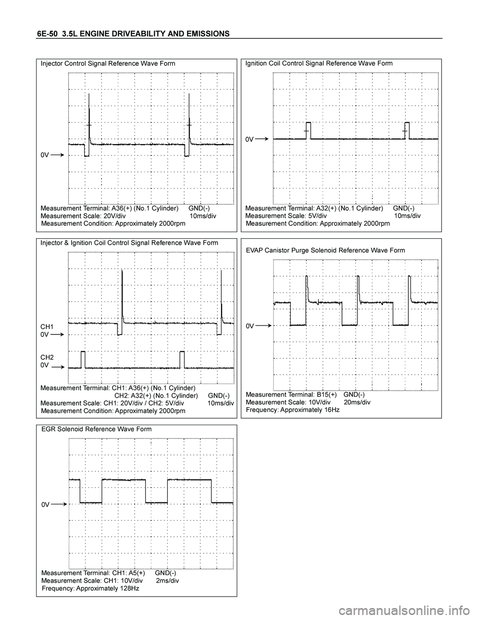
Injector Control Signal Reference Wave Form
0V
Measurement Terminal: A36(+) (No.1 Cylinder) GND(-)
Measurement Scale: 20V/div 10ms/div
Measurement Condition: Approximately 2000rpm
Ignition Coil Control Signal Reference Wave Form
0V
Measurement Terminal: A32(+) (No.1 Cylinder) GND(-)
Measurement Scale: 5V/div 10ms/div
Measurement Condition: Approximately 2000rpm
Injector & Ignition Coil Control Signal Reference Wave Form
CH1
0V
CH2
0V
Measurement Terminal: CH1: A36(+) (No.1 Cylinder)
CH2: A32(+) (No.1 Cylinder) GND(-)
Measurement Scale: CH1: 20V/div / CH2: 5V/div 10ms/div
Measurement Condition: Approximately 2000rpm
EVAP Canistor Purge Solenoid Reference Wave Form
0V
Measurement Terminal: B15(+) GND(-)
Measurement Scale: 10V/div 20ms/div
Frequency: Approximately 16Hz
EGR Solenoid Reference Wave Form
0V
Measurement Terminal: CH1: A5(+) GND(-)
Measurement Scale: CH1: 10V/div 2ms/div
Frequency: Approximately 128Hz
Page 2049 of 4264
3.5L ENGINE DRIVEABILITY AND EMISSIONS 6E-53
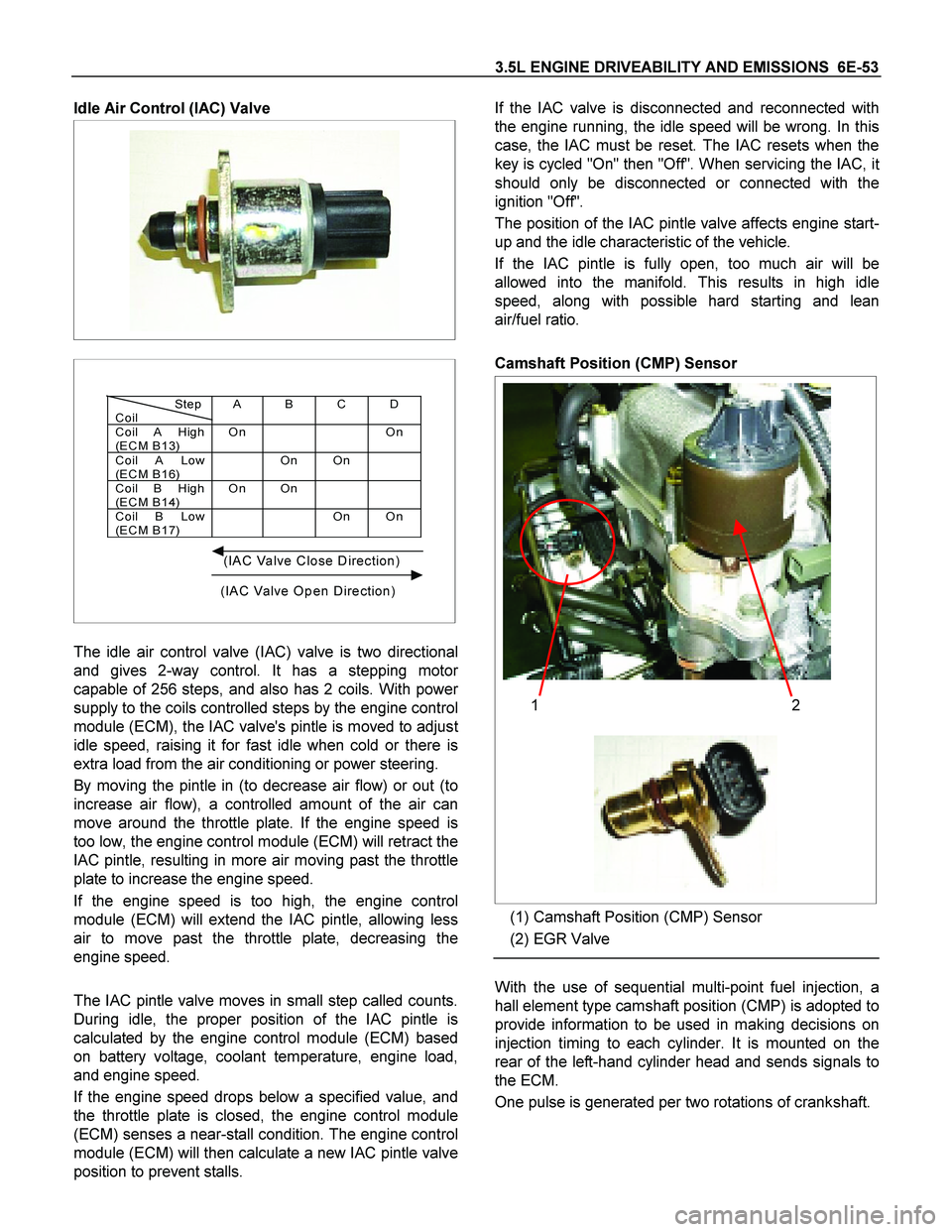
Idle Air Control (IAC) Valve
Step
CoilAB CD
Coil A High
(EC M B13)On On
Coil A Low
(EC M B16)On On
Coil B High
(EC M B14)On On
Coil B Low
(EC M B17)On On
(IAC Valve Close Direction)
(IAC Valve Open Direction)
The idle air control valve (IAC) valve is two directional
and gives 2-way control. It has a stepping moto
r
capable of 256 steps, and also has 2 coils. With power
supply to the coils controlled steps by the engine control
module (ECM), the IAC valve's pintle is moved to adjus
t
idle speed, raising it for fast idle when cold or there is
extra load from the air conditioning or power steering.
By moving the pintle in (to decrease air flow) or out (to
increase air flow), a controlled amount of the air can
move around the throttle plate. If the engine speed is
too low, the engine control module (ECM) will retract the
IAC pintle, resulting in more air moving past the throttle
plate to increase the engine speed.
If the engine speed is too high, the engine control
module (ECM) will extend the IAC pintle, allowing less
air to move past the throttle plate, decreasing the
engine speed.
The IAC pintle valve moves in small step called counts.
During idle, the proper position of the IAC pintle is
calculated by the engine control module (ECM) based
on battery voltage, coolant temperature, engine load,
and engine speed.
If the engine speed drops below a specified value, and
the throttle plate is closed, the engine control module
(ECM) senses a near-stall condition. The engine control
module (ECM) will then calculate a new IAC pintle valve
position to prevent stalls. If the IAC valve is disconnected and reconnected with
the engine running, the idle speed will be wrong. In this
case, the IAC must be reset. The IAC resets when the
key is cycled "On" then "Off". When servicing the IAC, i
t
should only be disconnected or connected with the
ignition "Off".
The position of the IAC pintle valve affects engine start-
up and the idle characteristic of the vehicle.
If the IAC pintle is fully open, too much air will be
allowed into the manifold. This results in high idle
speed, along with possible hard starting and lean
air/fuel ratio.
Camshaft Position (CMP) Sensor
12
(1) Camshaft Position (CMP) Sensor
(2) EGR Valve
With the use of sequential multi-point fuel injection, a
hall element type camshaft position (CMP) is adopted to
provide information to be used in making decisions on
injection timing to each cylinder. It is mounted on the
rear of the left-hand cylinder head and sends signals to
the ECM.
One pulse is generated per two rotations of crankshaft.