Page 2215 of 4264
 Yes No
6
1. Using the Tech 2, ignition \"On\" and engine \"Off\".
2. Monitor the \"Throttle Position\" in the data display.")
3.5L ENGINE DRIVEABILITY AND EMISSIONS 6E-219
Step Action Value (s) Yes No
6
1. Using the Tech 2, ignition "On" and engine "Off".
2. Monitor the "Throttle Position" in the data display.
Does the Tech 2 indicate correct "Throttle Position"
from 0% to 100% depending on accelerator pedal
operation?
- Go to Step 8 Go to Step 7
7
1. Using the Tech 2, ignition "On" and engine "Off".
2. Monitor the "Throttle Position" in the data display.
3. Adjust the TPS within 0% to 100%.
Is the action complete?
- Verify repair -
8
Check for the following conditions.
� Objects blocking the throttle valve.
� Vacuum leaking at throttle body.
If a problem is found, repair as necessary.
Was the problem found?
- Verify repair Refer to DTC
P0121 and Go to
Step 9
9
1. Using the Tech 2, ignition "On" and engine "On".
2. Select the "Miscellaneous Test" and perform the
"IAC Control" in the "IAC System".
3. Operate the Tech 2 in accrodance with procedure.
Was the engine speed changed, when the IAC Valve
is operating step by step?
-
Go to Step 11
Go to Step 10
10
Check for the following conditions.
� Objects blocking the IAC Valve.
� Objects blocking the throttle valve.
� Vacuum leaking at throttle body.
If a problem is found, repair as necessary.
Was the problem found?
- Verify repair Refer to DTC
P1508/P1509
and Go to Step
11
11
Check for injector for the affected bank.
Refer to 6E-106 "Injector Coil Test & Injector Balance
Test Procedure".
Was the injector operation correct?
- Go to Step 12 Refer to Injector
Coil Test &
Injector Balance
Test Procedure
12
Check for fuel pressure.
Refer to 6E-116 "Fuel System Diagnosis".
Was the fuel pressure correct?
- Go to Step 13 Refer to Fuel
System
Diagnosis
13
Replace the O2 sensor for the affected bank.
Was the problem solved?
- Verify repair Go to Step 14
14
Is the ECM programmed with the latest software
release?
If not, download the latest software to the ECM using
the "SPS (Service Programming System)".
Was the problem solved?
- Verify repair Go to Step 15
Page 2220 of 4264
 Yes No
6
1. Using the Tech 2, ignition \"On\" and engine \"Off\".
2. Monitor the \"Throttle Position\" in the data display.")
6E-224 3.5L ENGINE DRIVEABILITY AND EMISSIONS
Step Action Value (s) Yes No
6
1. Using the Tech 2, ignition "On" and engine "Off".
2. Monitor the "Throttle Position" in the data display.
Does the Tech 2 indicate correct "Throttle Position"
from 0% to 100% depending on accelerator pedal
operation?
- Go to Step 8 Go to Step 7
7
1. Using the Tech 2, ignition "On" and engine "Off".
2. Monitor the "Throttle Position" in the data display.
3. Adjust the TPS within 0% to 100%.
Is the action complete?
- Verify repair -
8
Check for the following conditions.
� Objects blocking the throttle valve.
� Vacuum leaking at throttle body.
If a problem is found, repair as necessary.
Was the problem found?
- Verify repair Refer to DTC
P0121 and Go to
Step 9
9
1. Using the Tech 2, ignition "On" and engine "On".
2. Select the "Miscellaneous Test" and perform the
"IAC Control" in the "IAC System".
3. Operate the Tech 2 in accrodance with procedure.
Was the engine speed changed, when the IAC Valve
is operating step by step?
-
Go to Step 10
Go to Step 10
10
Check for the following conditions.
� Objects blocking the IAC Valve.
� Objects blocking the throttle valve.
� Vacuum leaking at throttle body.
If a problem is found, repair as necessary.
Was the problem found?
- Verify repair Refer to DTC
P1508/P1509
and Go to Step
11
11
Check for injector for the affected bank.
Refer to 6E-106 "Injector Coil Test & Injector Balance
Test Procedure".
Was the injector operation correct?
- Go to Step 12 Refer to Injector
Coil Test &
Injector Balance
Test Procedure
12
Check for fuel pressure.
Refer to 6E-116 "Fuel System Diagnosis".
Was the fuel pressure correct?
- Go to Step 13 Refer to Fuel
System
Diagnosis
13
Replace the O2 sensor for the affected bank.
Was the problem solved?
- Verify repair Go to Step 14
14
Is the ECM programmed with the latest software
release?
If not, download the latest software to the ECM using
the "SPS (Service Programming System)".
Was the problem solved?
- Verify repair Go to Step 15
Page 2225 of 4264
3.5L ENGINE DRIVEABILITY AND EMISSIONS 6E-229
Step Action Value (s) Yes No
4
Check for poor/faulty connection at the injector or
ECM connector. If a poor/faulty connection is found,
repair as necessary.
Was the problem found?
E-61(B)
�
��
E-60(A)��
����
E-6/E-7/E-8/E-9/
E-51/E-52
��
- Verify repair Go to Step 5
5
Visually check the injector for affected cylinder.
Was the problem found?
- Go to Step 11 Go to Step 6
6
Using the DVM and check the injector coil.
1. Ignition "Off", engine "Off".
2. Disconnect injector connector for the affected
cylinder.
3. Measure the resistance of injector coil.
Does the tester indicate standard resistance?
�
�
�� ��
�� �
��Injector
Approximately
15� at 20�C
Go to Step 7
Go to Step 11
Page 2246 of 4264

P0351")
6E-250 3.5L ENGINE DRIVEABILITY AND EMISSIONS
Condition For Setting The DTC and Action Taken When The DTC Sets
Flash
Code Code Type DTC Name DTC Setting Condition Fail-Safe (Back Up)
P0351 A Ignition 1 Control
Circuit
P0352 A Ignition 2 Control
Circuit
P0353 A Ignition 3 Control
Circuit
P0354 A Ignition 4 Control
Circuit
P0355 A Ignition 5 Control
Circuit
42
P0356 A Ignition 6 Control
Circuit 1. No DTC relating to CMP sensor and CKP sensor.
2. Engine speed is between 250rpm and 850 rpm.
3. 10 ignition signals are not detected consecutively. Fuel cut is operated more than
2000rpm.
CIRCUIT DESCRIPTION
The Engine Control Module's (ECM) control circuit 1
provides a zero-volt or a 5-volt output signal to the
ignition coil. The normal voltage on the circuit is zero
volts. When the ignition coil receives the 5-volt signal
from the ECM, it provides a ground path for the B+
supply to the primary side of the number 1 ignition coil.
When the ECM shuts off the 5 volts to the ignition coil,
the ignition coil turns “OFF." This causes the ignition coil
primary magnetic field to collapse, producing a voltage
in the secondary coil which fires the spark plug.
The circuit between the ECM and ignition coil is
monitored for an open circuit, short to voltage, and shor
t
to ground. When the ECM detects a problem on ignition
control circuit, it will set a DTC P0351, P0352, P0353,
P0354, P0355 or P0356.
DIAGNOSTIC AIDS
Check for the following conditions:
Poor connection at ECM – Inspect the harness
connectors for backed-out terminals, imprope
r
mating, broken locks, improperly formed or damaged
terminals, and poor terminal-to-wire connections.
Damaged harness –Inspect the wiring harness fo
r
damage. If the harness appears to be OK, observe
the Tech 2 display related to DTC P0351 or P0352,
P0353, P0354, P0355 or P0356 while moving the
connector and wiring related to the ignition system.
A
change in the display will indicate the location of the
fault.
Reviewing the Failure Records vehicle mileage since
the diagnostic test last failed may help determine ho
w
often the condition that caused the DTC to be set
occurs. This may assist in diagnosing the condition.
Page 2248 of 4264
6E-252 3.5L ENGINE DRIVEABILITY AND EMISSIONS
Step Action Value (s) Yes No
4
Check for poor/faulty connection at the ignition coil or
ECM connector. If a poor/faulty connection is found,
repair as necessary.
Was the problem found?
E-60(A)
E-61(B)
E-53/E-54/E-55/
E-56/E-57/E-58
E-73/E-74
��
����
�
��
��
�
- Verify repair Go to Step 5
5
Visually check the ignition coil for the affected cylinder.
Was the problem found?
- Go to Step 12 Go to Step 6
6
Using the DVM and check the ignition coil signal
circuit for the affected cylinder.
1. Ignition "On", engine "Off".
2. Disconnect the ignition coil connector for the
affected cylinder.
3. Check the circuit for short to battery voltage circuit.
Was the DVM indicated battery voltage?
E-53/E-54/E-55/
E-56/E-57/E-58
V
�
-
Repair faulty
harness and
verify repair
Go to Step 7
Page 2249 of 4264
3.5L ENGINE DRIVEABILITY AND EMISSIONS 6E-253
Step Action Value (s) Yes No
7
Using the DVM and check the ignition coil signal
circuit for the affected cylinder.
Breaker box is available:
1. Ignition "Off", engine "Off".
2. Install the breaker box as type A (ECM
disconnected).
Refer to 6E-95 page.
3. Disconnect the ignition coil connector for the
affected cylinder.
4. Check the circuit for open or short to ground circuit.
Was the problem found?
A32
Breaker Box No.1 Cylinder
�
E-53
�
�
B7
Breaker Box No.2 Cylinder
�
E-54
�
�
A31
Breaker Box No.3 Cylinder
�
E-55
�
�
B8
Breaker Box No.4 Cylinder
�
E-56
�
�
A30
Breaker Box No.5 Cylinder
�
E-57
�
�
Page 2250 of 4264
6E-254 3.5L ENGINE DRIVEABILITY AND EMISSIONS
Step Action Value (s) Yes No
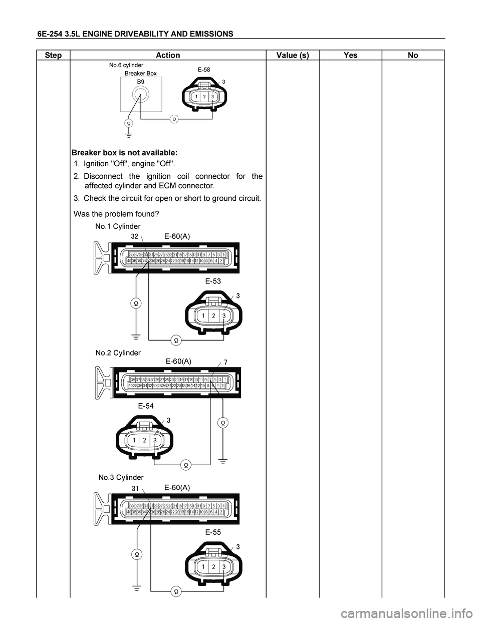
B9
Breaker Box No.6 cylinder
�
E-58
�
�
Breaker box is not available:
1. Ignition "Off", engine "Off".
2. Disconnect the ignition coil connector for the
affected cylinder and ECM connector.
3. Check the circuit for open or short to ground circuit.
Was the problem found?
E-60(A)
E-53
�
�
�
�� No.1 Cylinder
E-60(A)
E-54
�
�
�
�
No.2 Cylinder
E-60(A)
E-55
�
�
�
�� No.3 Cylinder
Page 2252 of 4264
6E-256 3.5L ENGINE DRIVEABILITY AND EMISSIONS
Step Action Value (s) Yes No
8
Using the DVM and check the ignition coil power
supply circuit.
1. Ignition "On", engine "Off".
2. Disconnect the ignition coil connector for the
affected cylinder.
3. Check the circuit for open circuit.
Was the DVM indicated specified value?
E-53/E-54/E-55/
E-56/E-57/E-58
V
�
10-14.5V
Go to Step 10
Go to Step 9
9
Repair the open or short to ground circuit between the
"IGN. COIL" (15A) and ignition coil for the affected
cylinder.
Is the action complete?
- Verify repair -
10
Using the DVM and check the ignition coil ground
circuit for the affected cylinder.
1. Ignition "On", engine "Off".
2. Disconnect the ignition coil connector for the
affected cylinder.
3. Check the circuit for short to power supply circuit.
Was the DVM indicated specified value?
E-53/E-54/E-55/
E-56/E-57/E-58
V
�
Less than 1V
Go to Step 11
Repair faulty
harness and
verify repair
 Yes No
4
Check for poor/faulty connection at the injector or
ECM connector. If a poor/faulty connection is found,
repair a")
 Yes No
4
Check for poor/faulty connection at the ignition coil or
ECM connector. If a poor/faulty connection is found,
rep")
 Yes No
7
Using the DVM and check the ignition coil signal
circuit for the affected cylinder.
Breaker box is available:")
 Yes No
8
Using the DVM and check the ignition coil power
supply circuit.
1. Ignition \"On\", engine \"Off\".
2. Disconnect")