Page 4007 of 4264
DIAGNOSIS (JR405E) 7A2-15
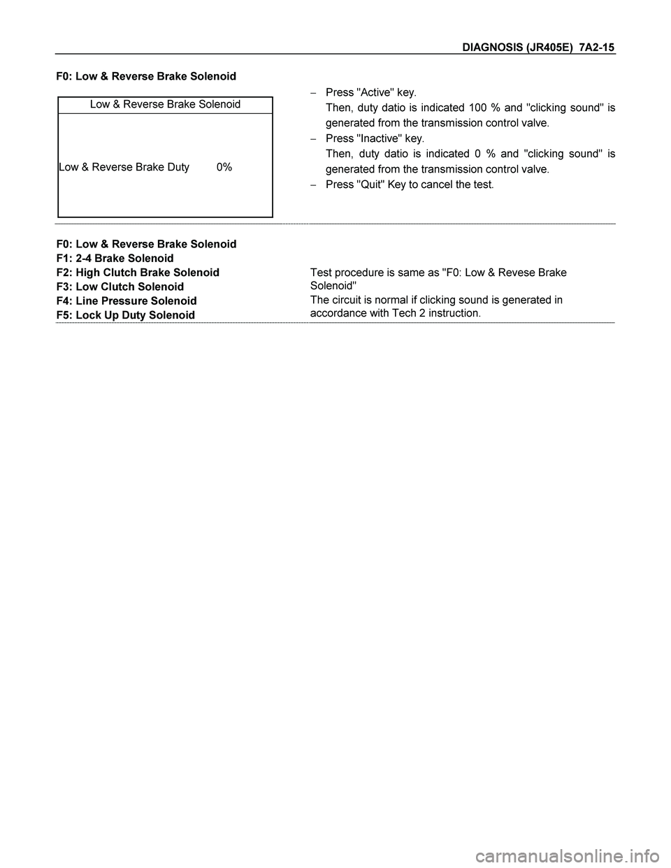
F0: Low & Reverse Brake Solenoid
Low & Reverse Brake Solenoid
Low & Reverse Brake Duty 0%
� Press "Active" key.
Then, duty datio is indicated 100 % and "clicking sound" is
generated from the transmission control valve.
� Press "Inactive" key.
Then, duty datio is indicated 0 % and "clicking sound" is
generated from the transmission control valve.
� Press "Quit" Key to cancel the test.
F0: Low & Reverse Brake Solenoid
F1: 2-4 Brake Solenoid
F2: High Clutch Brake Solenoid
F3: Low Clutch Solenoid
F4: Line Pressure Solenoid
F5: Lock Up Duty Solenoid
Test procedure is same as "F0: Low & Revese Brake
Solenoid"
The circuit is normal if clicking sound is generated in
accordance with Tech 2 instruction.
Page 4025 of 4264
DIAGNOSIS (JR405E) 7A2-33
DIAGNOSIS TROUBLE CODE TABLE
Flash Code
(P-Code)
CHECK TRANS Flash Pattern
Description
CHECK
TRANS
Warning
11 (P0722) Vehicle Speed Sensor No Signal ON
12 (-) Normal -
13 (P0727) ON
Engine Revolution Sensor No
Signal
14 (P0717) Turbine Speed Sensor No Signal ON
15 (P0710) ATF Temperature Sensor FailureOFF
16 (P0560) System Voltage Failure ON
17 (P0705) Inhibitor Switch Failure ON
22 (P1120) Throttle Signal Failure ON
25 (P1875) GND Return Circuit Failure ON
26 (P1853) ON
Low & Reverse Brake Pressure
Switch Failure
27 (P1858) 2-4 Brake Pressure Switch FailureON
28 (P1863) ON
High Clutch Pressure Switch
Failure
31 (P0753) ON
Low & Reverse Brake Duty
Solenoid Failure
32 (P0758) 2-4BrakeDutySolenoidFailure ON
33 (P0763) ON
High Clutch Duty Solenoid Failure
Page 4026 of 4264
7A2-34 DIAGNOSIS (JR405E)
Flash Code
(P-Code)
CHECK TRANS Flash Pattern
Description
CHECK
TRANS
Warning
34 (P0768) Low Clutch Duty Solenoid FailureON
35 (P0748) Line Pressure Solenoid Failure ON
36 (P1860) Lock-up Duty Solenoid Failure ON
41 (P0731) 1stGearRatioError ON
42 (P0732) 2ndGearRatioError ON
43 (P0733) 3rdGearRatioError ON
44 (P0734) 4thGearRatioError ON
51 (P1750) ON
Low & Reverse Brake Fail-safe
Valve Failure
52 (P1755) 2-4BrakeFail-safeValveFailure ON
- (P0602) No Flash Code ECU Programming Error ON
Page 4027 of 4264
 7A2-35
FAIL-SAFEFUNCTION
Fail-Safe Condition
Flash Code
(P-Code)
Description
CHECK
TRANS
Warning
Gear Shift
Solenoid
Line
Pressure
Solenoid
Lock-up
Remark")
DIAGNOSIS (JR405E) 7A2-35
FAIL-SAFEFUNCTION
Fail-Safe Condition
Flash Code
(P-Code)
Description
CHECK
TRANS
Warning
Gear Shift
Solenoid
Line
Pressure
Solenoid
Lock-up
Remark
11
(P0722)
Vehicle peed Sensor No
Signal ON 3rdFix All Stop - Inhibited
13
(P0727)
Engine Revolution Sensor
No Signal ON - - - Inhibited
14
(P0717)
Turbine Speed Sensor No
Signal ON 3rdFix All Stop - Inhibited
15
(P0710)
ATF Temperature Sensor
Failure OFF 3,2,L - - Inhibited*1
16
(P0560)
System Voltage Failure ON 3rdFix All Stop - Inhibited*2
17
(P0705)
Inhibitor Switch Failure ON 3rdFix All Stop - Inhibited
22
(P1120)
Throttle Signal Failure ON 3rdFix All Stop - Inhibited
25
(P1875)
GND Return Circuit
Failure ON 3rdFix All Stop - Inhibited*2
26
(P1853)
Low & Reverse Brake
Pressure Switch Failure ON No Fail-safe Function
27
(P1858)
2-4 Brake Pressure
Switch Failure ON No Fail-safe Function
28
(P1863)
High Clutch Pressure
Switch Failure ON No Fail-safe Function
31
(P0753)
Low & Reverse Brake
Duty Solenoid Failure ON 3rdFix All Stop - Inhibited
32
(P0758)
2-4 Brake Duty Solenoid
Failure ON 3rdFix All Stop - Inhibited
33
(P0763)
High Clutch Duty Solenoid
Failure ON 3rdFix All Stop - Inhibited
34
(P0768)
Low Clutch Duty Solenoid
Failure ON 3rdFix All Stop - Inhibited
35
(P0748)
Line Pressure Solenoid
Failure ON - - Stop -
36
(P1860)
Lock-up Duty Solenoid
Failure ON - - - Inhibited
41
(P0731)
1stGearRatioError ON No Fail-safe Function
42
(P0732)
2ndGearRatioError ON No Fail-safe Function
43
(P0733)
3rdGearRatioError ON No Fail-safe Function
44
(P0734)
4thGearRatioError ON No Fail-safe Function
51
(P1750)
Low & Reverse Brake
Fail-safe Valve Failure ON 3rdFix All Stop - Inhibited
52
(P1755)
2-4 Brake Fail-safe Valve
Failure ON 3rdFix All Stop - Inhibited
-
(P0602)
ECU Programming Error ON No Fail-safe Function
*1: When the engine speed is more than 470 rpm for 10 minuets, the lock-up and gear shift to 4th (over-drive) are
allowed.
*2: In case of fail-safe valve failure, gear shift to 4th (over-drive) is inhibited.
Page 4032 of 4264

DTC P0717 (Flash Code 14) Turbine Speed Sensor No Signal
Turbine
Sensor TCM
B3
H23 (9)C95 (3) E31 (2)
(1)
(3)
E10
Key SW
BRN/RED
WHT
BLK BRN")
7A2-40 DIAGNOSIS (JR405E)
DTC P0717 (Flash Code 14) Turbine Speed Sensor No Signal
Turbine
Sensor TCM
B3
H23 (9)C95 (3) E31 (2)
(1)
(3)
E10
Key SW
BRN/RED
WHT
BLK BRN/RED
Speed Sensor Turbine Sensor
Setting Condition:
� The turbine speed below 300 rpm for 2 seconds while the vehicle is running at the speed over 40 km/h with the
engine speed over 1500 rpm in the D, 3, 2, or L range.
Fail Safe:
� When the vehicle is running, the gear position selected at the trouble detection is held and the lock-up is
inhibited.
� After the vehicle stopped, all solenoid operations stop (OFF) and the gear is fixed to the 3rd.
Possible Cause:
� Turbine speed sensor malfunction.
� Sensor wheel (reverse & high clutch drum) malfunction.
� Large sensing gap between speed sensor and sensor wheel (reverse & high clutch drum).
� Sensor wire open circuit, short circuit to battery or short circuit to ground between turbine speed sensor terminal
1 and TCM terminal B3 (C95).
� Sensor wire open circuit or short circuit to ground between turbine speed sensor terminal 2 and power supply
circuit.
� Sensor wire open circuit or short circuit to battery between turbine speed sensor terminal 3 and ground circuit.
� Poor connection of each connector.
Page 4039 of 4264
DIAGNOSIS (JR405E) 7A2-47
DTC P1875 (Flash Code 25) GND Return Circuit Failure
Control Valve
TCM
B6
B7
B8
B9
B22 (GND)
BLU/BLK
WHT/BLU
L&R Brake Solenoid
Terminal
Assembly
BLK/YEL
RED 2-4 Brake Solenoid
High Clutch Solenoid
Low Clutch Solenoid
E54
(5)
(9)
(10)
(3)
(11) H23 (11)
(5)
(7)
(2)
(1)
GRY/REDC95
(6)
(7)
(8)
(9)
(22)
BLU/BLK
BLK/YEL RED
WHT/BLU
GRY/RED
Setting Condition:
� Ground return circuit is failed 7 times continuously after the low & reverse brake duty solenoid output signal turn
on.
Fail Safe:
� All solenoid operations are stopped (OFF), the gear is fixed to the 3rd, and the lock-up is inhibited. (In case of
fail-safe valve failure, gear shift to 4th (over-drive) and lock-up are inhibited.)
Possible Cause:
� Ground return wire open circuit between terminal assembly terminal 11 and TCM terminal B22 (C95).
� Poor connection of each connector.
Page 4040 of 4264
7A2-48 DIAGNOSIS (JR405E)
DTC P0753 (Flash Code 31) Low & Reverse Brake Duty Solenoid Failure
Control Valve
TCM
B6
B7
B8
B9
B22 (GND)
BLU/BLK
WHT/BLU
L&R Brake Solenoid
Terminal
Assembly
BLK/YEL
RED 2-4 Brake Solenoid
High Clutch Solenoid
Low Clutch Solenoid
E54
(5)
(9)
(10)
(3)
(11) H23 (11)
(5)
(7)
(2)
(1)
GRY/REDC95
(6)
(7)
(8)
(9)
(22)
BLU/BLK
BLK/YEL RED
WHT/BLU
GRY/RED
Page 4041 of 4264
 7A2-49
Gear Position & Shift Solenoid Operation
Range TCM terminal
Gear B8
(High clutch
solenoid) B9
(Low clutch
solenoid) B7
(2-4 brake
solenoid) B6
(Low & rev")
DIAGNOSIS (JR405E) 7A2-49
Gear Position & Shift Solenoid Operation
Range TCM terminal
Gear B8
(High clutch
solenoid) B9
(Low clutch
solenoid) B7
(2-4 brake
solenoid) B6
(Low & reverse
brake solenoid)
P � �
R Reverse � �
N � �
D, 3, 2 1st �
2nd � �
3rd � �
4th � �
L 1st � �
2nd � �
3rd � �
4th � �
: On (Operated)
� : Off (Not operated)
Setting Condition:
� The low & reverse brake duty solenoid signal is open circuit or short circuit.
(The voltage different from the output ON/OFF signals was detected while the TCM monitors the solenoid output
voltage.)
Fail Safe:
� When the vehicle is running, the operation of the low & reverse brake duty solenoid and the lock-up solenoid is
stopped (OFF), the gear position selected at the trouble detection is held, and the lock-up is inhibited.
� After the vehicle stopped, all solenoid operations stop (OFF) and the gear is fixed to the 3rd.
Possible Cause:
� Low & reverse brake duty solenoid malfunction.
� Open (Off) circuit or short (On) circuit harness of the low & reverse brake duty solenoid.
� Open circuit, short circuit to battery or short circuit to ground between low & reverse brake duty solenoid terminal
5 and TCM terminal B6 (C96).
� Insufficient ground condition of the low & reverse brake duty solenoid.
� Poor connection of each connector.
 7A2-33
DIAGNOSIS TROUBLE CODE TABLE
Flash Code
(P-Code)
CHECK TRANS Flash Pattern
Description
CHECK
TRANS
Warning
11 (P0722)")

Flash Code
(P-Code)
CHECK TRANS Flash Pattern
Description
CHECK
TRANS
Warning
34 (P0768) Low Clutch Duty S")
 7A2-47
DTC P1875 (Flash Code 25) GND Return Circuit Failure
Control Valve
TCM
B6")

DTC P0753 (Flash Code 31) Low & Reverse Brake Duty Solenoid Failure
Control Valve
TCM
B6")