Page 541 of 4264
CAB 10-33
Important Operations
15. Instrument Panel & Crass Beam Assembly
1) Tighten the 4 bolts fixing the cross beam and body panel
to the specified torque.
Torque N�
m (kgf�
m/lb�
ft)
19 (1.9/14)
2) A Bolt: Steering Column to Cross Beam
Torque N�
m (kgf�
m/lb�
ft)
20 (2.0/14)
B Bolt: Pedal Bracket to Cross Beam
Torque N�
m (kgf�
m/lb�
ft)
15 (1.5/11)
3) C Bolt: Parking Brake Bracket to Cross Beam
Torque N�m (kgf�m/lb�ft)
15 (1.5/11)
21. Steering Wheel/Steering Cowl
� Tighten the steering wheel fixing nut to the specified
truque.
Torque N�
m (kgf�
m/lb�
ft)
35 (3.6/26)
Page 624 of 4264
7C-22 CLUTCH
Important Operations - Removal
1. Transmission Assembly
Refer to “MANUAL TRANSMISSION” of section 7B and 7B1
for “REMOVAL AND INSTALLATION” procedure.
2. Clutch Pressure Plate Assembly
3. Driven Plate Assembly
(1) Use the clutch pilot aligner
1 to prevent the driven plate
assembly
2 from falling free.
Clutch Pilot Aligner : 5-85253-001-0
(2) Loosen the clutch cover bolts in the numerical order shown
in the illustration.
(3) Remove the pressure plate assembly
3 from the flywheel.
(4) Remove the driven plate from the flywheel.
201RS017
220RW088-X
4. Release Bearing (6VE1)
5. Shift Fork (6VE1)
(1) Remove the release bearing (1) from the transmission
case.
(2) Remove the shift fork snap pin (2).
(3) Remove the shift fork pin and shift fork (3) from the fulcrum
bridge.
6VE1 4JH1-TC, C24SE
Page 625 of 4264
CLUTCH 7C-23
015RW053
6. Flywheel Assembly and Crank Bearing (6VE1)
(1) Remove flywheel assembly and crankshaft bearing. Do no
t
remove except for replacement.
(2) Use the remover 5-8840-2000-0 (J-5822) and sliding
hammer 5-8840-0019-0 (J-23907) to remove the crankshaf
t
bearing
Important Operations - Installation
Follow the removal procedure in reverse order to perform the
installation procedure.
Pay careful attention to the important points during the
installation procedure.
015RW054
6. Flywheel Assembly and Crank Bearing (6VE1)
(1) Install flywheel assembly and crankshaft bearing. Use the
installer 5-8840-0125-0 (J-26516-A) and driver handle 5-
8840-0007-0 (J-8092) to install the crankshaft bearing then
clean and lubricate with grease.
015RS047
(2) Install new flywheel fixing bolts in the order illustrated and
tighten them to the specified torque.
N�
m (kg�
m/lb ft)
6VE1 54 (5.5/40)
NOTE: Do not reuse the bolt and do not apply oil or thread lock
to the bolt.
Page 627 of 4264
CLUTCH 7C-25
(4) Clean the pressure plate surfaces.
(5) Align the pressure plate assembly
4 with the flywheel
knock pin
5.
(6) Install the pressure plate assembly to the flywheel.
(7) Tighten the clutch cover bolts a little at a time in the
numerical order shown in the illustration.
Clutch Cover Bolt Torque N�
m (kgf�
m/lb�
ft)
18 �
3 (1.8 �
0.3 / 13.0 �
2.2)
201RS017
(8) Remove the clutch pilot aligner.
Note:
Do not strike the clutch pilot aligner with a hammer to
remove it.
4JH1-TC, C24SE
6VE1
Page 629 of 4264

CLUTCH 7C-27
201R300011
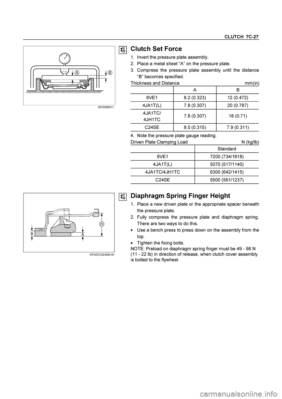
Clutch Set Force
1. Invert the pressure plate assembly.
2. Place a metal sheet “A” on the pressure plate.
3. Compress the pressure plate assembly until the distance
“B” becomes specified.
Thickness and Distance mm(in
)
A B
6VE1 8.2 (0.323) 12 (0.472)
4JA1T(L) 7.8 (0.307) 20 (0.787)
4JA1TC/
4JH1TC 7.8 (0.307) 18 (0.71)
C24SE 8.0 (0.315) 7.9 (0.311)
4. Note the pressure plate gauge reading.
Driven Plate Clamping Load N (kg/Ib)
Standard
6VE1 7200 (734/1618)
4JA1T(L) 5070 (517/1140)
4JA1TC/4JH1TC 6300 (642/1415)
C24SE 5500 (561/1237)
RTW37CSH000101
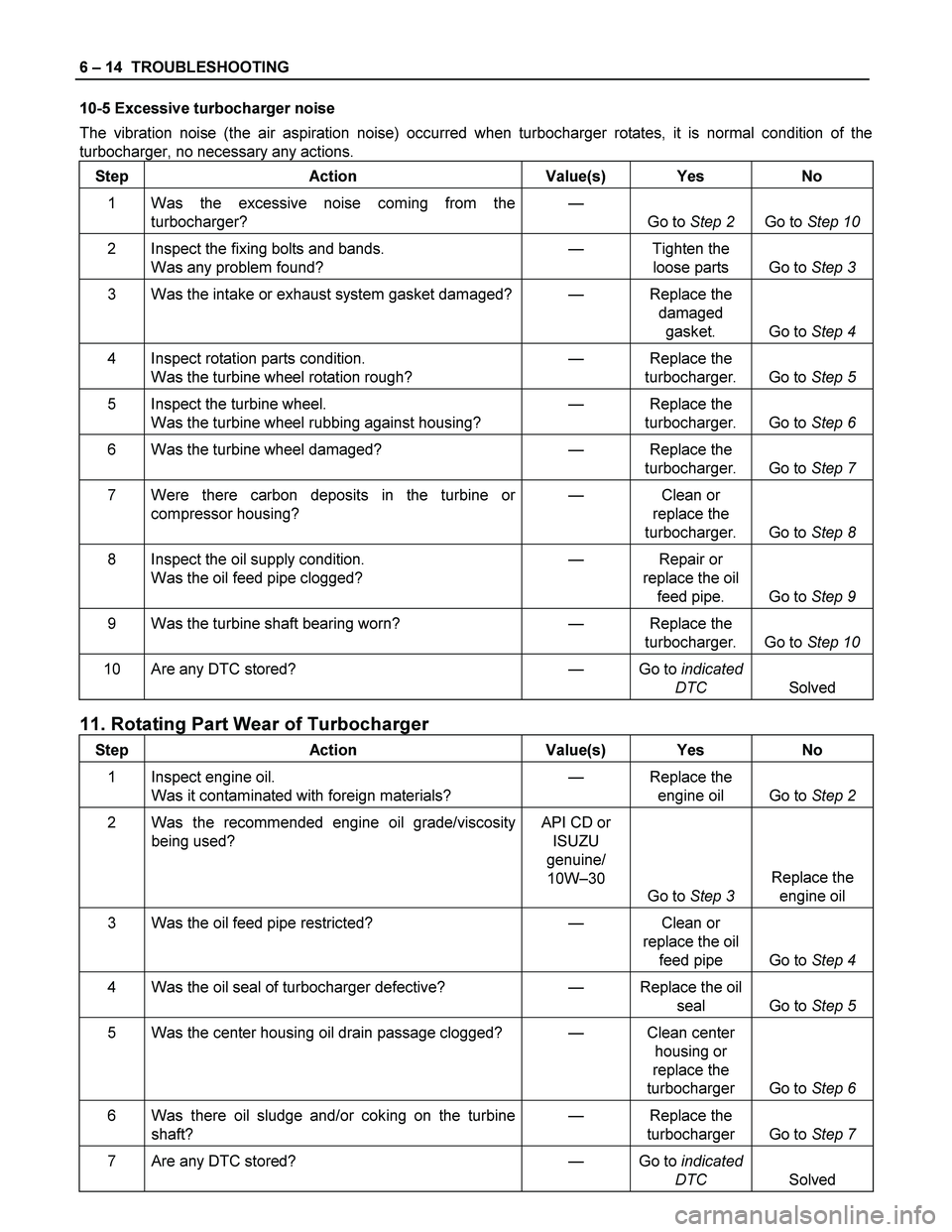
Diaphragm Spring Finger Height
1. Place a new driven plate or the appropriate spacer beneath
the pressure plate.
2. Fully compress the pressure plate and diaphragm spring.
There are two ways to do this.
�
Use a bench press to press down on the assembly from the
top.
� Tighten the fixing bolts.
NOTE: Preload on diaphragm spring finger must be 49 - 98 N
(11 - 22 lb) in direction of release, when clutch cover assembly
is bolted to the flywheel.
Page 1134 of 4264

6 – 14 TROUBLESHOOTING
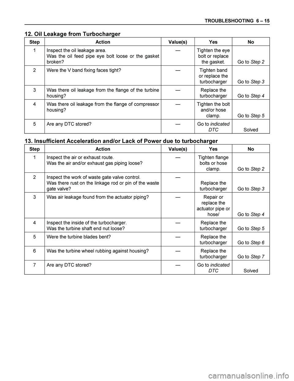
10-5 Excessive turbocharger noise
The vibration noise (the air aspiration noise) occurred when turbocharger rotates, it is normal condition of the
turbocharger, no necessary any actions.
Step Action Value(s) Yes No
1 Was the excessive noise coming from the
turbocharger? —
Go to Step 2 Go to Step 10
2 Inspect the fixing bolts and bands.
Was any problem found? — Tighten the
loose parts Go to Step 3
3 Was the intake or exhaust system gasket damaged?— Replace the
damaged
gasket. Go to Step 4
4 Inspect rotation parts condition.
Was the turbine wheel rotation rough? — Replace the
turbocharger. Go to Step 5
5 Inspect the turbine wheel.
Was the turbine wheel rubbing against housing? — Replace the
turbocharger. Go to Step 6
6 Was the turbine wheel damaged? — Replace the
turbocharger. Go to Step 7
7 Were there carbon deposits in the turbine or
compressor housing? — Clean or
replace the
turbocharger. Go to Step 8
8 Inspect the oil supply condition.
Was the oil feed pipe clogged? — Repair or
replace the oil
feed pipe. Go to Step 9
9 Was the turbine shaft bearing worn? — Replace the
turbocharger. Go to Step 10
10 Are any DTC stored? — Go to indicated
DTC Solved
11. Rotating Part Wear of Turbocharger
Step Action Value(s) Yes No
1 Inspect engine oil.
Was it contaminated with foreign materials? — Replace the
engine oil Go to Step 2
2 Was the recommended engine oil grade/viscosity
being used? API CD or
ISUZU
genuine/
10W–30
Go to Step 3 Replace the
engine oil
3 Was the oil feed pipe restricted? — Clean or
replace the oil
feed pipe Go to Step 4
4 Was the oil seal of turbocharger defective? — Replace the oil
seal Go to Step 5
5 Was the center housing oil drain passage clogged? — Clean center
housing or
replace the
turbocharger Go to Step 6
6 Was there oil sludge and/or coking on the turbine
shaft? — Replace the
turbocharger Go to Step 7
7 Are any DTC stored? — Go to indicated
DTC Solved
Page 1135 of 4264

TROUBLESHOOTING 6 – 15
12. Oil Leakage from Turbocharger
Step Action Value(s) Yes No
1 Inspect the oil leakage area.
Was the oil feed pipe eye bolt loose or the gasket
broken? — Tighten the eye
bolt or replace
the gasket. Go to Step 2
2 Were the V band fixing faces tight? — Tighten band
or replace the
turbocharger Go to Step 3
3 Was there oil leakage from the flange of the turbine
housing? — Replace the
turbocharger Go to Step 4
4 Was there oil leakage from the flange of compressor
housing? — Tighten the bolt
and/or hose
clamp. Go to Step 5
5 Are any DTC stored? — Go to indicated
DTC Solved
13. Insufficient Acceleration and/or Lack of Power due to turbocharger
Step Action Value(s) Yes No
1 Inspect the air or exhaust route.
Was the air and/or exhaust gas piping loose? — Tighten flange
bolts or hose
clamp. Go to Step 2
2 Inspect the work of waste gate valve control.
Was there rust on the linkage rod or pin of the waste
gate valve? —
Replace the
turbocharger Go to Step 3
3 Was air leakage found from the actuator piping? — Repair or
replace the
actuator pipe or
hose/ Go to Step 4
4 Inspect the inside of the turbocharger.
Was the turbine shaft end nut loose? — Replace the
turbocharger Go to Step 5
5 Were the turbine blades bent? — Replace the
turbocharger Go to Step 6
6 Was the turbine wheel rubbing against housing? — Replace the
turbocharger Go to Step 7
7 Are any DTC stored? — Go to indicated
DTC Solved
Page 1174 of 4264

6A – 34 ENGINE MECHANICAL
RTW46ASH000701
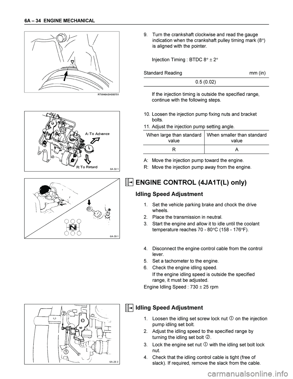
9. Turn the crankshaft clockwise and read the gauge
indication when the crankshaft pulley timing mark (8�)
is aligned with the pointer.
Injection Timing : BTDC 8� � 2�
Standard Reading mm (in)
0.5 (0.02)
If the injection timing is outside the specified range,
continue with the following steps.
10. Loosen the injection pump fixing nuts and bracket
bolts.
11. Adjust the injection pump setting angle.
When large than standard
value When smaller than standard
value
R A
A: Move the injection pump toward the engine.
R: Move the injection pump away from the engine.
ENGINE CONTROL (4JA1T(L) only)
Idling Speed Adjustment
1. Set the vehicle parking brake and chock the drive
wheels.
2. Place the transmission in neutral.
3. Start the engine and allow it to idle until the coolant
temperature reaches 70 - 80�C (158 - 176�F).
4. Disconnect the engine control cable from the control
lever.
5. Set a tachometer to the engine.
6. Check the engine idling speed.
If the engine idling speed is outside the specified
range, it must be adjusted.
Engine Idling Speed : 730 � 25 rpm
Idling Speed Adjustment
1. Loosen the idling set screw lock nut � on the injection
pump idling set bolt.
2. Adjust the idling speed to the specified range by
turning the idling set bolt
�.
3. Lock the engine set nut
� with the idling set bolt lock
nut.
4. Check that the idling control cable is tight (free of
slack). If required, remove the slack from the cable.