Page 2431 of 4264
ENGINE MECHANICAL (C24SE) 6A-11
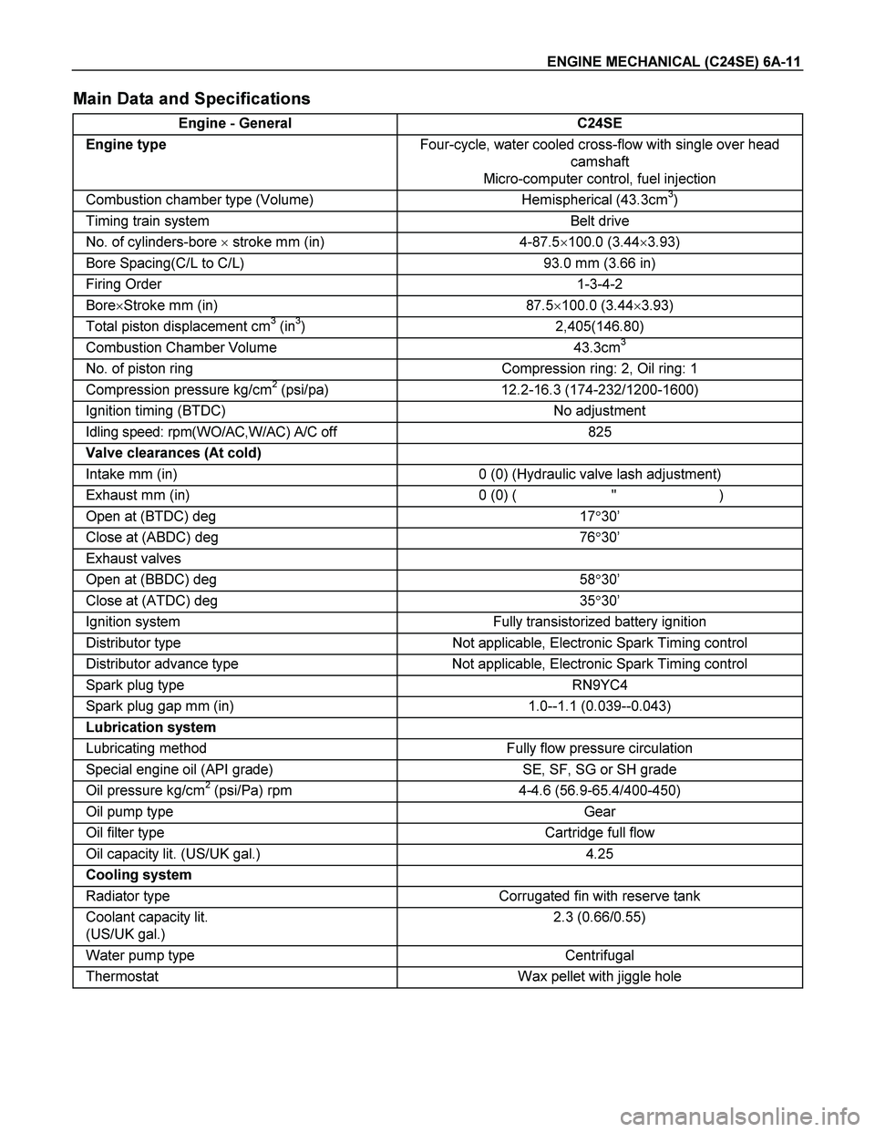
Main Data and Specifications
Engine - General C24SE
Engine type Four-cycle, water cooled cross-flow with single over head
camshaft
Micro-computer control, fuel injection
Combustion chamber type (Volume) Hemispherical (43.3cm3)
Timing train system Belt drive
No. of cylinders-bore � stroke mm (in) 4-87.5�100.0 (3.44�3.93)
Bore Spacing(C/L to C/L) 93.0 mm (3.66 in)
Firing Order 1-3-4-2
Bore�Stroke mm (in) 87.5�100.0 (3.44�3.93)
Total piston displacement cm3 (in3) 2,405(146.80)
Combustion Chamber Volume 43.3cm3
No. of piston ring Compression ring: 2, Oil ring: 1
Compression pressure kg/cm2 (psi/pa) 12.2-16.3 (174-232/1200-1600)
Ignition timing (BTDC) No adjustment
Idling speed: rpm(WO/AC,W/AC) A/C off 825
Valve clearances (At cold)
Intake mm (in) 0 (0) (Hydraulic valve lash adjustment)
Exhaust mm (in) 0 (0) ( " )
Open at (BTDC) deg 17�30’
Close at (ABDC) deg 76�30’
Exhaust valves
Open at (BBDC) deg 58�30’
Close at (ATDC) deg 35�30’
Ignition system Fully transistorized battery ignition
Distributor type Not applicable, Electronic Spark Timing control
Distributor advance type Not applicable, Electronic Spark Timing control
Spark plug type RN9YC4
Spark plug gap mm (in) 1.0--1.1 (0.039--0.043)
Lubrication system
Lubricating method Fully flow pressure circulation
Special engine oil (API grade) SE, SF, SG or SH grade
Oil pressure kg/cm2 (psi/Pa) rpm 4-4.6 (56.9-65.4/400-450)
Oil pump type Gear
Oil filter type Cartridge full flow
Oil capacity lit. (US/UK gal.) 4.25
Cooling system
Radiator type Corrugated fin with reserve tank
Coolant capacity lit.
(US/UK gal.) 2.3 (0.66/0.55)
Water pump type Centrifugal
Thermostat Wax pellet with jiggle hole
Page 2483 of 4264
ENGINE MECHANICAL (C24SE) 6A-63
OPERATIONS ON COOLING SYSTEM
Caution!
Before working with the cooling system, be sure to confirm that
the temperature of the engine is cooled down.
Failure to observe this may cause burn.
Cooling System, Check for Leaks
Installation
1. Install commercially available coolant checking
instrument onto compensation tank (Refer to section 6B;
Engine cooling).
2. Check coolant level.
Inspection
Use 5-8840-0277-0 tester & 5-8840-2603-0 adaptor.
Cooling System, Fill Up and Bleed
Important!
Radiator and heater core are made from alminium.
To avoid corrosion, use only anti-freeze with corrosion
protection.
Replace Coolant
1. Confirm the engine is cold enough.
2. Open the radiator cap, pour coolant to the filler neck level
and close the cap.
3. Pour coolant into the reservoir until MAX line is reached.
4. Start the engine, run 2 �
3 minutes at idling speed and
switch off the engine.
5. Refill coolant if the coolant level is lowered.
Page 2484 of 4264
6A-64 ENGINE MECHANICAL (C24SE)
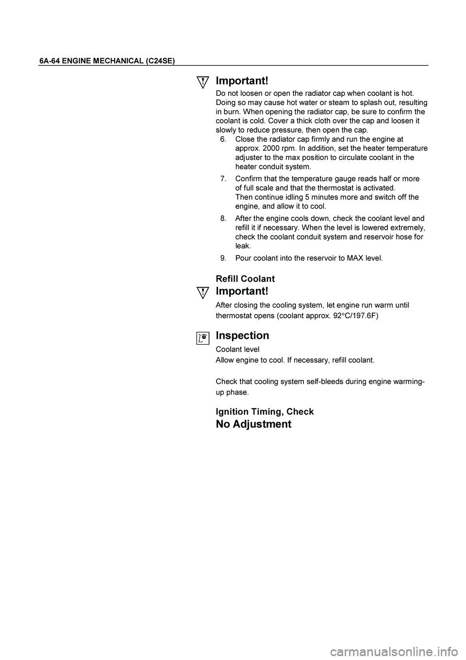
Important!
Do not loosen or open the radiator cap when coolant is hot.
Doing so may cause hot water or steam to splash out, resulting
in burn. When opening the radiator cap, be sure to confirm the
coolant is cold. Cover a thick cloth over the cap and loosen it
slowly to reduce pressure, then open the cap.
6. Close the radiator cap firmly and run the engine at
approx. 2000 rpm. In addition, set the heater temperature
adjuster to the max position to circulate coolant in the
heater conduit system.
7. Confirm that the temperature gauge reads half or more
of full scale and that the thermostat is activated.
Then continue idling 5 minutes more and switch off the
engine, and allow it to cool.
8. After the engine cools down, check the coolant level and
refill it if necessary. When the level is lowered extremely,
check the coolant conduit system and reservoir hose for
leak.
9. Pour coolant into the reservoir to MAX level.
Refill Coolant
Important!
After closing the cooling system, let engine run warm until
thermostat opens (coolant approx. 92�C/197.6F)
Inspection
Coolant level
Allow engine to cool. If necessary, refill coolant.
Check that cooling system self-bleeds during engine warming-
up phase.
Ignition Timing, Check
No Adjustment
Page 2497 of 4264
ENGINE MECHANICAL (C24SE) 6A-77
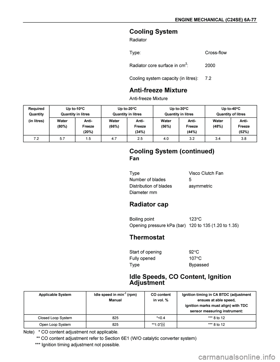
Cooling System
Radiator
Type: Cross-flow
Radiator core surface in cm
2: 2000
Cooling system capacity (in litres): 7.2
Anti-freeze Mixture
Anti-freeze Mixture
Required
Quantity Up to-10�
�� �C
Quantity in litres Up to-20�
�� �C
Quantity in litres Up to-30�
�� �C
Quantity in litres Up to-40�
�� �C
Quantity of litres
(in litres) Water
(80%) Anti-
Freeze
(20%) Water
(66%) Anti-
Freeze
(34%) Water
(56%) Anti-
Freeze
(44%) Water
(48%) Anti-
Freeze
(52%)
7.2 5.7 1.5 4.7 2.5 4.0 3.2 3.4 3.8
Cooling System (continued)
Fan
Type Visco Clutch Fan
Number of blades 5
Distribution of blades asymmetric
Diameter mm
Radiator cap
Boiling point 123�C
Opening pressure kPa (bar) 120 to 135 (1.20 to 1.35)
Thermostat
Start of opening 92�C
Fully opened 107�C
Type Bypassed
Idle Speeds, CO Content, Ignition
Adjustment
Applicable System Idle speed in min-1 (rpm)
Manual CO content
in vol. % Ignition timing in CA BTDC (adjustment
ensues at able speed,
ignition marks must align) with TDC
sensor measuring instrument:
Closed Loop System 825 *<0.4 *** 8 to 12
Open Loop System 825
**1.0+0.2
-0.5 *** 8 to 12
Note) * CO content adjustment not applicable.
** CO content adjustment refer to Section 6E1 (W/O catalytic converter system)
*** Ignition timing adjustment not possible.
Page 2515 of 4264
ENGINE COOLING 6B-5
Diagnosis
Engine Cooling Trouble
Condition Possible cause Correction
Engine overheating Low Engine Coolant level Replenish
Thermo mater unit faulty Replace
Faulty thermostat Replace
Faulty Engine Coolant temperature
sensor Repair or replace
Clogged radiator Clean or replace
Faulty radiator cap Replace
Low engine oil level or use of
improper engine oil Replenish or change oil
Clogged exhaust system Clean exhaust system or replace
faulty parts
Faulty Throttle Position sensor Replace throttle valve assembly
Open or shorted Throttle Position
sensor circuit Repair or replace
Damaged cylinder head gasket Replace
Loosen V-belt tension Adjust belt tension or replace.
Collapsed hoses Replace
Faulty Fan clutch Replace
Engine overcooling Faulty thermostat Replace
Engine slow to warm-up Faulty thermostat Replace
Thermo unit faulty Replace
Page 2516 of 4264
6B-6 ENGINE COOLING
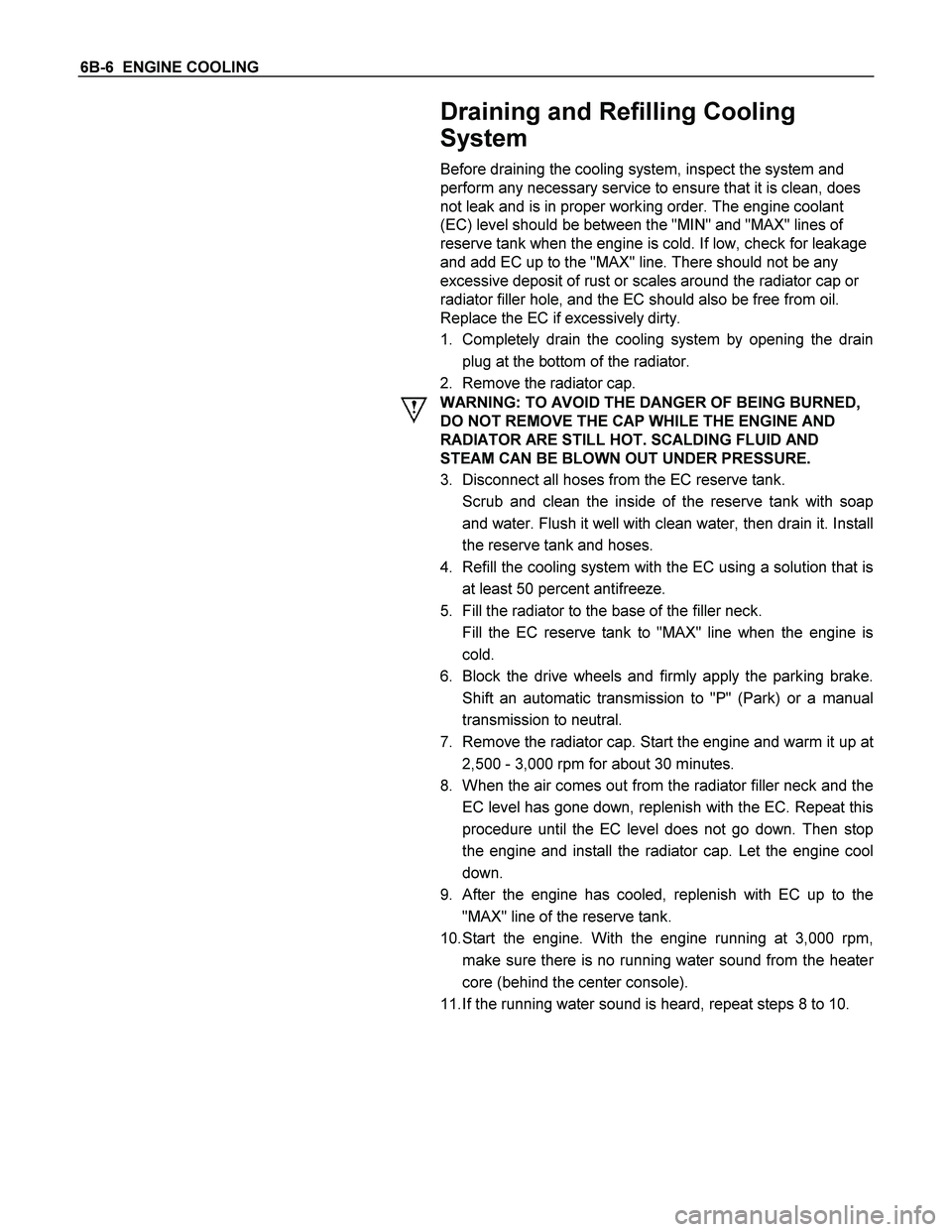
Draining and Refilling Cooling
System
Before draining the cooling system, inspect the system and
perform any necessary service to ensure that it is clean, does
not leak and is in proper working order. The engine coolant
(EC) level should be between the "MIN" and "MAX" lines of
reserve tank when the engine is cold. If low, check for leakage
and add EC up to the "MAX" line. There should not be any
excessive deposit of rust or scales around the radiator cap or
radiator filler hole, and the EC should also be free from oil.
Replace the EC if excessively dirty.
1. Completely drain the cooling system by opening the drain
plug at the bottom of the radiator.
2. Remove the radiator cap.
WARNING: TO AVOID THE DANGER OF BEING BURNED,
DO NOT REMOVE THE CAP WHILE THE ENGINE AND
RADIATOR ARE STILL HOT. SCALDING FLUID AND
STEAM CAN BE BLOWN OUT UNDER PRESSURE.
3. Disconnect all hoses from the EC reserve tank.
Scrub and clean the inside of the reserve tank with soap
and water. Flush it well with clean water, then drain it. Install
the reserve tank and hoses.
4. Refill the cooling system with the EC using a solution that is
at least 50 percent antifreeze.
5. Fill the radiator to the base of the filler neck.
Fill the EC reserve tank to "MAX" line when the engine is
cold.
6. Block the drive wheels and firmly apply the parking brake.
Shift an automatic transmission to "P" (Park) or a manual
transmission to neutral.
7. Remove the radiator cap. Start the engine and warm it up a
t
2,500 - 3,000 rpm for about 30 minutes.
8. When the air comes out from the radiator filler neck and the
EC level has gone down, replenish with the EC. Repeat this
procedure until the EC level does not go down. Then stop
the engine and install the radiator cap. Let the engine cool
down.
9. After the engine has cooled, replenish with EC up to the
"MAX" line of the reserve tank.
10. Start the engine. With the engine running at 3,000 rpm,
make sure there is no running water sound from the heate
r
core (behind the center console).
11. If the running water sound is heard, repeat steps 8 to 10.
Page 2521 of 4264
ENGINE COOLING 6B-11
Radiator
Radiator and Associated Parts
Legend
1 Radiator Hose
2 Drain Plug
3 Fan Guide, Lower
4 Fan Guide
5 Bracket 6 Reserve Tank Hose
7 Reserve Tank
8 Radiator Cap
9 Radiator Assembly
Removal
1. Disconnect battery ground cable.
2. Loosen a drain plug to drain engine coolant (EC).
3. Disconnect radiator inlet hose and outlet hose.
4. Disconnect the reserve tank hose from radiator.
5. Lift out the radiator assembly, taking care not to damage
the radiator core.
Page 2522 of 4264
6B-12 ENGINE COOLING
Inspection
Radiator Cap
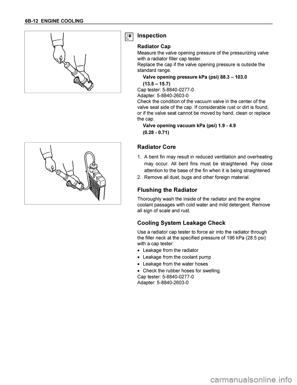
Measure the valve opening pressure of the pressurizing valve
with a radiator filler cap tester.
Replace the cap if the valve opening pressure is outside the
standard range.
Valve opening pressure kPa (psi) 88.3 – 103.0
(13.5 – 15.7)
Cap tester: 5-8840-0277-0
Adapter: 5-8840-2603-0
Check the condition of the vacuum valve in the center of the
valve seat side of the cap. If considerable rust or dirt is found,
or if the valve seat cannot be moved by hand, clean or replace
the cap.
Valve opening vacuum kPa (psi) 1.9 - 4.9
(0.28 - 0.71)
Radiator Core
1. A bent fin may result in reduced ventilation and overheating
may occur. All bent fins must be straightened. Pay close
attention to the base of the fin when it is being straightened.
2. Remove all dust, bugs and other foreign material.
Flushing the Radiator
Thoroughly wash the inside of the radiator and the engine
coolant passages with cold water and mild detergent. Remove
all sign of scale and rust.
Cooling System Leakage Check
Use a radiator cap tester to force air into the radiator through
the filler neck at the specified pressure of 196 kPa (28.5 psi)
with a cap tester:
� Leakage from the radiator
� Leakage from the coolant pump
� Leakage from the water hoses
� Check the rubber hoses for swelling.
Cap tester: 5-8840-0277-0
Adapter: 5-8840-2603-0