Page 4028 of 4264

7A2-36 DIAGNOSIS (JR405E)
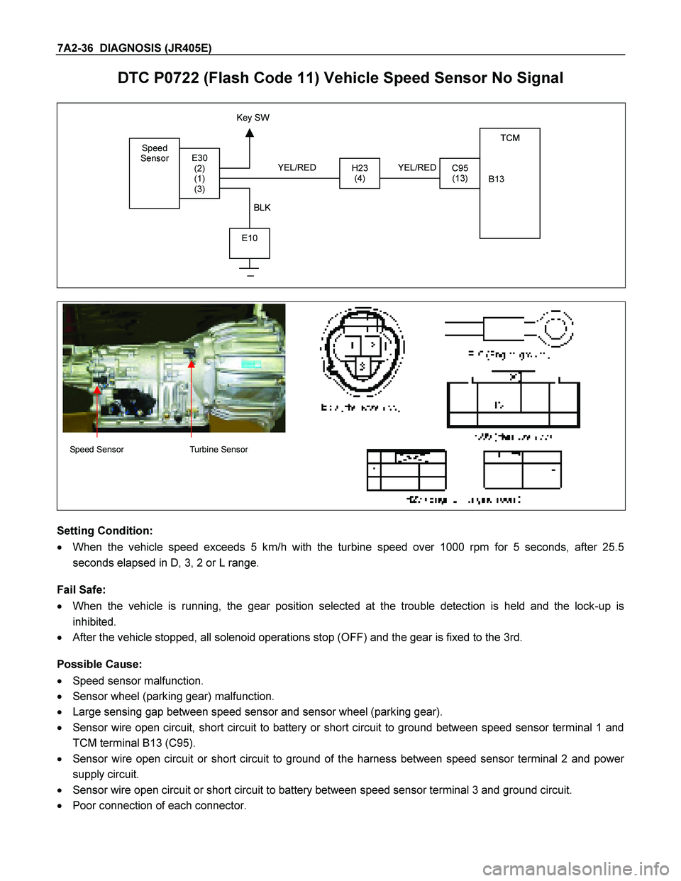
DTC P0722 (Flash Code 11) Vehicle Speed Sensor No Signal
Speed
Sensor
TCM
B13
H23
(4)C95
(13)E30
(2)
(1)
(3)
E10
Key SW
YEL/RED
BLK YEL/RED
Speed Sensor Turbine Sensor
Setting Condition:
� When the vehicle speed exceeds 5 km/h with the turbine speed over 1000 rpm for 5 seconds, after 25.5
seconds elapsed in D, 3, 2 or L range.
Fail Safe:
� When the vehicle is running, the gear position selected at the trouble detection is held and the lock-up is
inhibited.
� After the vehicle stopped, all solenoid operations stop (OFF) and the gear is fixed to the 3rd.
Possible Cause:
� Speed sensor malfunction.
� Sensor wheel (parking gear) malfunction.
� Large sensing gap between speed sensor and sensor wheel (parking gear).
� Sensor wire open circuit, short circuit to battery or short circuit to ground between speed sensor terminal 1 and
TCM terminal B13 (C95).
� Sensor wire open circuit or short circuit to ground of the harness between speed sensor terminal 2 and power
supply circuit.
� Sensor wire open circuit or short circuit to battery between speed sensor terminal 3 and ground circuit.
� Poor connection of each connector.
Page 4032 of 4264

7A2-40 DIAGNOSIS (JR405E)
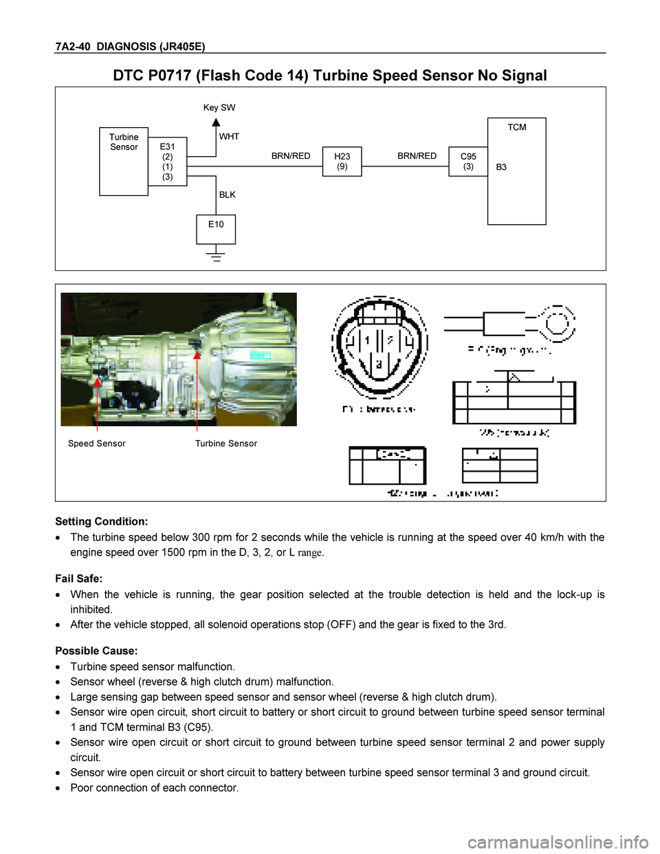
DTC P0717 (Flash Code 14) Turbine Speed Sensor No Signal
Turbine
Sensor TCM
B3
H23 (9)C95 (3) E31 (2)
(1)
(3)
E10
Key SW
BRN/RED
WHT
BLK BRN/RED
Speed Sensor Turbine Sensor
Setting Condition:
� The turbine speed below 300 rpm for 2 seconds while the vehicle is running at the speed over 40 km/h with the
engine speed over 1500 rpm in the D, 3, 2, or L range.
Fail Safe:
� When the vehicle is running, the gear position selected at the trouble detection is held and the lock-up is
inhibited.
� After the vehicle stopped, all solenoid operations stop (OFF) and the gear is fixed to the 3rd.
Possible Cause:
� Turbine speed sensor malfunction.
� Sensor wheel (reverse & high clutch drum) malfunction.
� Large sensing gap between speed sensor and sensor wheel (reverse & high clutch drum).
� Sensor wire open circuit, short circuit to battery or short circuit to ground between turbine speed sensor terminal
1 and TCM terminal B3 (C95).
� Sensor wire open circuit or short circuit to ground between turbine speed sensor terminal 2 and power supply
circuit.
� Sensor wire open circuit or short circuit to battery between turbine speed sensor terminal 3 and ground circuit.
� Poor connection of each connector.
Page 4111 of 4264

DIAGNOSIS (JR405E) 7A2-119
Step Action Yes No
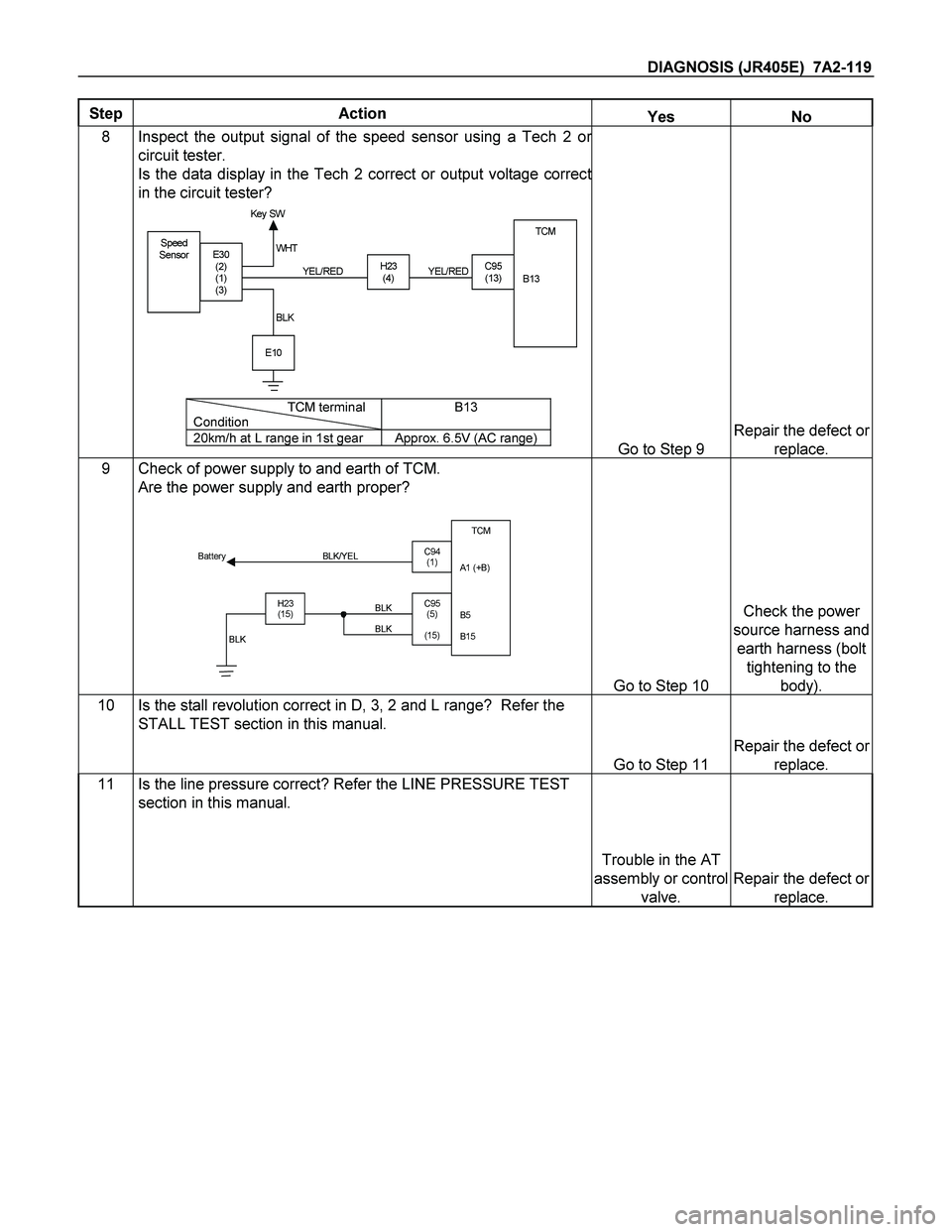
8 Inspect the output signal of the speed sensor using a Tech 2 or
circuit tester.
Is the data display in the Tech 2 correct or output voltage correct
in the circuit tester?
Speed
SensorTCM
B13
H23
(4)C95
(13)E30
(2)
(1)
(3)
E10
Key SW
YEL/RED WHT
BLKYEL/RED
TCM terminal
ConditionB13
20km/h at L range in 1st gear Approx. 6.5V (AC range)Go to Step 9
Repair the defect or
replace.
9 Check of power supply to and earth of TCM.
Are the power supply and earth proper?
TCM
A1 (+B)
B5
B15
H23
(15)C95
(5)
(15) BLK/YEL
BLK BLK Battery
C94
(1)
BLK
Go to Step 10
Check the power
source harness and
earth harness (bolt
tightening to the
body).
10 Is the stall revolution correct in D, 3, 2 and L range? Refer the
STALL TEST section in this manual.
Go to Step 11
Repair the defect or
replace.
11 Is the line pressure correct? Refer the LINE PRESSURE TEST
section in this manual.
Trouble in the AT
assembly or control
valve.
Repair the defect or
replace.