2004 ISUZU TF SERIES engine mount
[x] Cancel search: engine mountPage 1284 of 4264
6B – 4 ENGINE COOLING
GENERAL DESCRIPTION
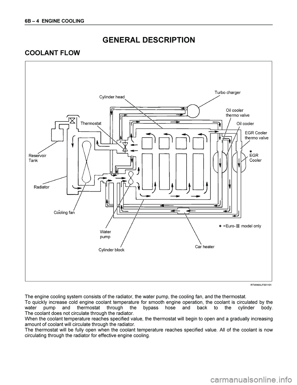
COOLANT FLOW
RTW46ALF001101
The engine cooling system consists of the radiator, the water pump, the cooling fan, and the thermostat.
To quickly increase cold engine coolant temperature for smooth engine operation, the coolant is circulated by the
water pump and thermostat through the bypass hose and back to the cylinder body.
The coolant does not circulate through the radiator.
When the coolant temperature reaches specified value, the thermostat will begin to open and a gradually increasing
amount of coolant will circulate through the radiator.
The thermostat will be fully open when the coolant temperature reaches specified value. All of the coolant is now
circulating through the radiator for effective engine cooling.
Page 1341 of 4264
ENGINE ELECTRICAL 6D – 3
GENERAL DESCRIPTION
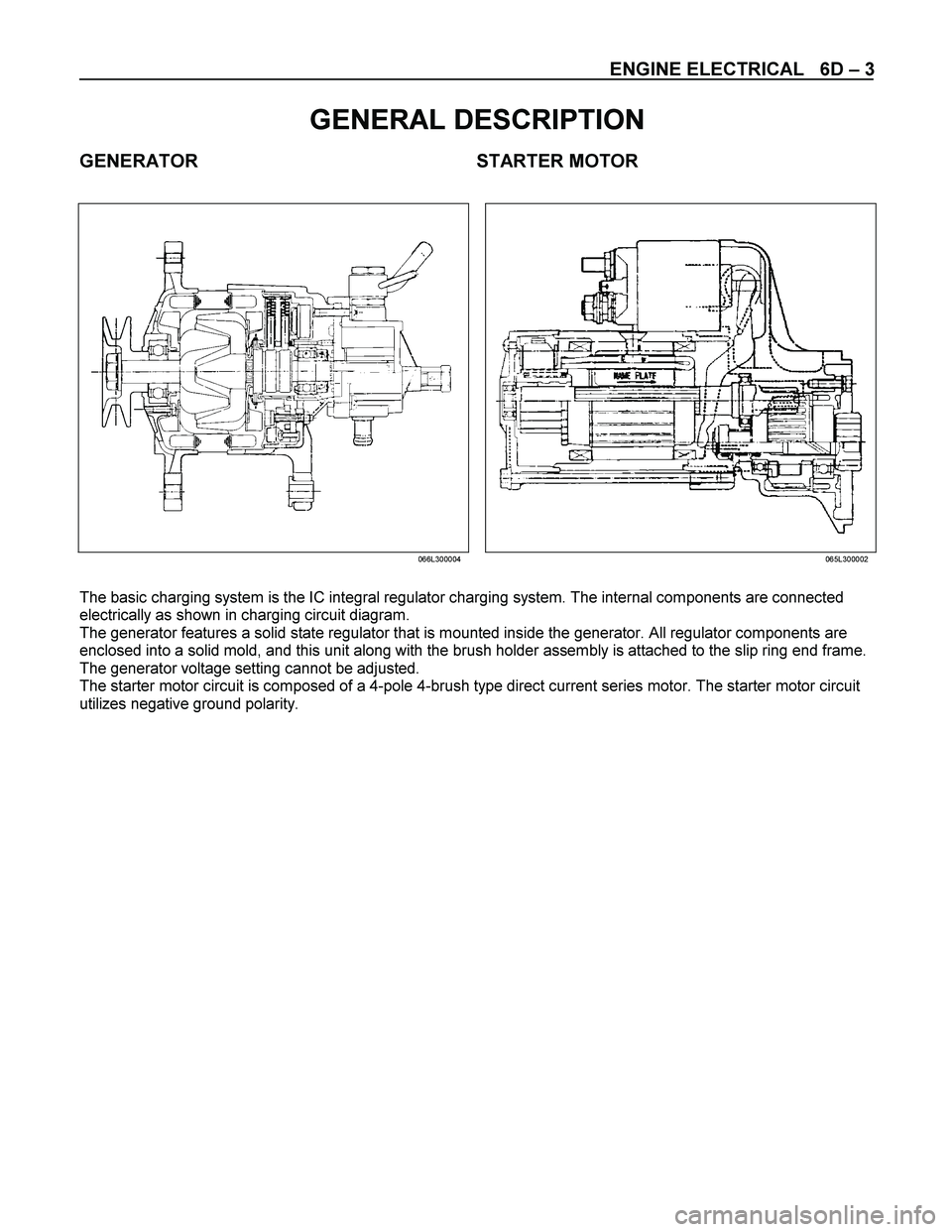
GENERATOR STARTER MOTOR
066L300004065L300002
The basic charging system is the IC integral regulator charging system. The internal components are connected
electrically as shown in charging circuit diagram.
The generator features a solid state regulator that is mounted inside the generator. All regulator components are
enclosed into a solid mold, and this unit along with the brush holder assembly is attached to the slip ring end frame.
The generator voltage setting cannot be adjusted.
The starter motor circuit is composed of a 4-pole 4-brush type direct current series motor. The starter motor circuit
utilizes negative ground polarity.
Page 1437 of 4264
4JA1/4JH1 ENGINE DRIVEABILITY AND EMISSIONS 6E–65
The following signals are ex changed via the CAN-bus:
From ECM to PSG
Desired injection quantity
Desired injection timing
Engine speed
From PSG to ECM
Fuel temperature
Pump speed
Cylinder identifier
Control pulse (actual injection quantity + actual
injection timing)
PSG status
Mass Air Flow (MAF) Sensor & Intake Air
Temperature (IAT) Sensor
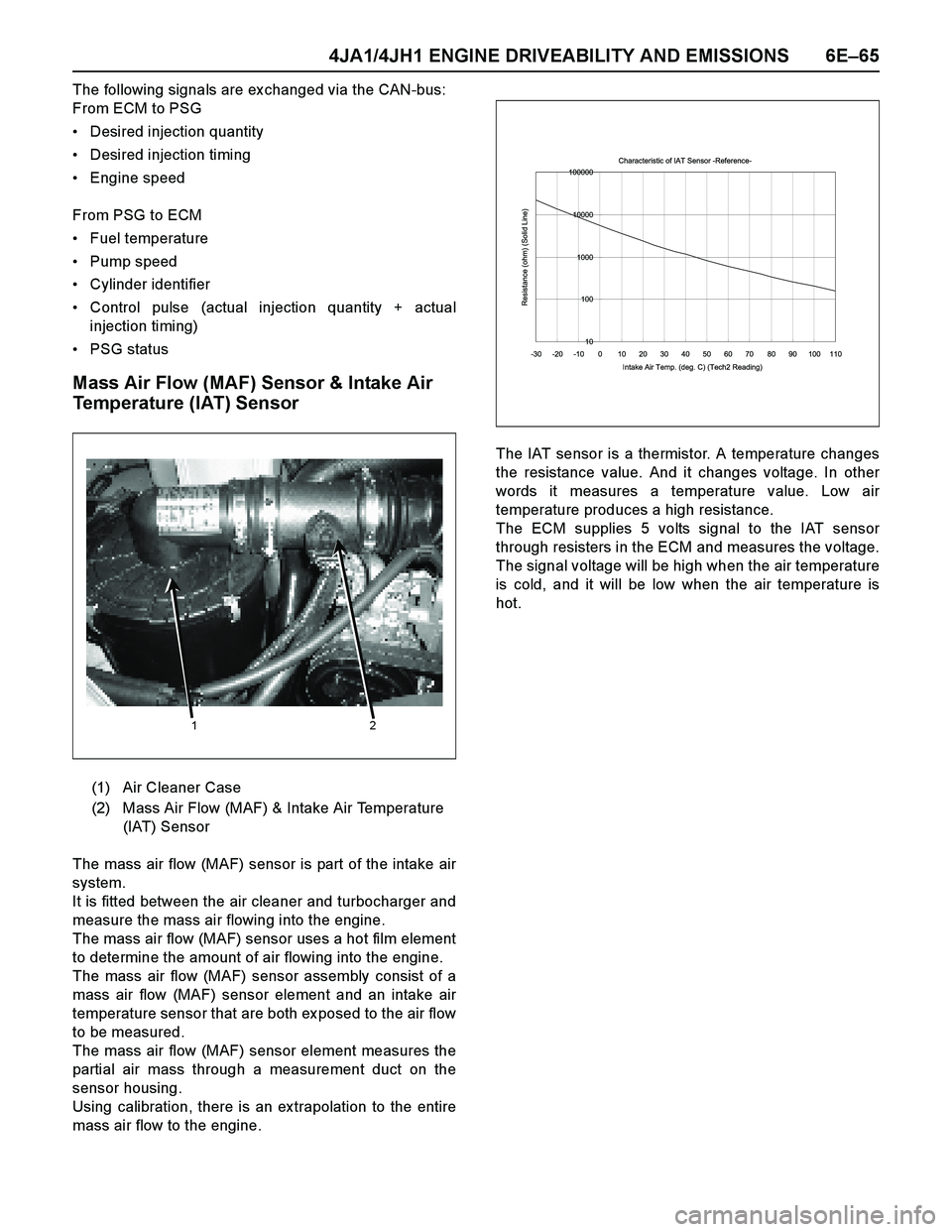
The mass air flow (MAF) sensor is part of the intake air
system.
It is fitted between the air cleaner and turbocharger and
measure the mass air flowing into the engine.
The mass air flow (MAF) sensor uses a hot film element
to determine the amount of air flowing into the engine.
The mass air flow (MAF) sensor assembly consist of a
mass air flow (MAF) sensor element and an intake air
temperature sensor that are both ex posed to the air flow
to be measured.
The mass air flow (MAF) sensor element measures the
partial air mass through a measurement duct on the
sensor housing.
Using calibration, there is an ex trapolation to the entire
mass air flow to the engine.The IAT sensor is a thermistor. A temperature changes
the resistance value. And it changes voltage. In other
words it measures a temperature value. Low air
temperature produces a high resistance.
The ECM supplies 5 volts signal to the IAT sensor
through resisters in the ECM and measures the voltage.
The signal voltage will be high when the air temperature
is cold, and it will be low when the air temperature is
hot.
(1) Air Cleaner Case
(2) Mass Air Flow (MAF) & Intake Air Temperature
(IAT) Sensor
1 2
Characteristic of IAT Sensor -Reference-
10 100 1000 10000 100000
-30 -20 -10 0 10 20 30 40 50 60 70 80 90 100 110
Intake Air Temp. (deg. C) (Tech2 Reading)
Resistance (ohm) (Solid Line)
Page 1440 of 4264
6E–68 4JA1/4JH1 ENGINE DRIVEABILITY AND EMISSIONS
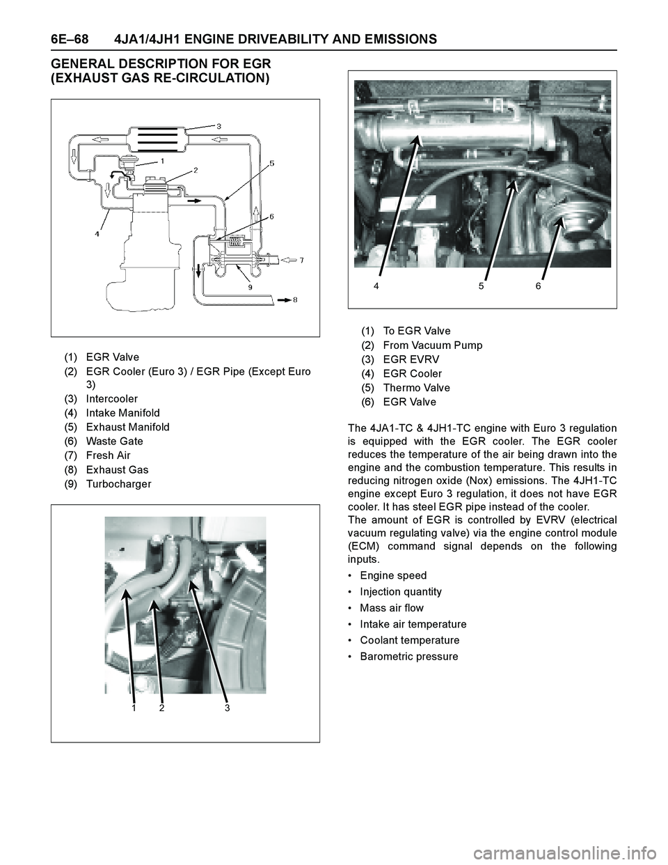
GENERAL DESCRIPTION FOR EGR
(EXHAUST GAS RE-CIRCULATION)
The 4JA1-TC & 4JH1-TC engine with Euro 3 regulation
is equipped with the EGR cooler. The EGR cooler
reduces the temperature of the air being drawn into the
engine and the combustion temperature. This results in
reducing nitrogen ox ide (Nox ) emissions. The 4JH1-TC
engine ex cept Euro 3 regulation, it does not have EGR
cooler. It has steel EGR pipe instead of the cooler.
The amount of EGR is controlled by EVRV (electrical
vacuum regulating valve) via the engine control module
(ECM) command signal depends on the following
inputs.
Engine speed
Injection quantity
Mass air flow
Intake air temperature
Coolant temperature
Barometric pressure (1) EGR Valve
(2) EGR Cooler (Euro 3) / EGR Pipe (Except Euro
3)
(3) Intercooler
(4) Intake Manifold
(5) Ex haust Manifold
(6) Waste Gate
(7) Fresh Air
(8) Ex haust Gas
(9) Turbocharger
123
(1) To EGR Valve
(2) From Vacuum Pump
(3) EGR EVRV
(4) EGR Cooler
(5) Thermo Valve
(6) EGR Valve
4 5 6
Page 1441 of 4264
4JA1/4JH1 ENGINE DRIVEABILITY AND EMISSIONS 6E–69
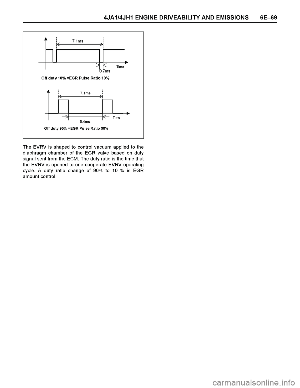
The EVRV is shaped to control vacuum applied to the
diaphragm chamber of the EGR valve based on duty
signal sent from the ECM. The duty ratio is the time that
the EVRV is opened to one cooperate EVRV operating
cycle. A duty ratio change of 90% to 10 % is EGR
amount control.
7.1m s
Time 0. 7m s Off duty 10% =EGR Pulse Ratio 10%
7.1ms
Ti m e 6.4ms Off duty 90% =EGR Pulse Ratio 90%
Page 1444 of 4264
6E–72 4JA1/4JH1 ENGINE DRIVEABILITY AND EMISSIONS
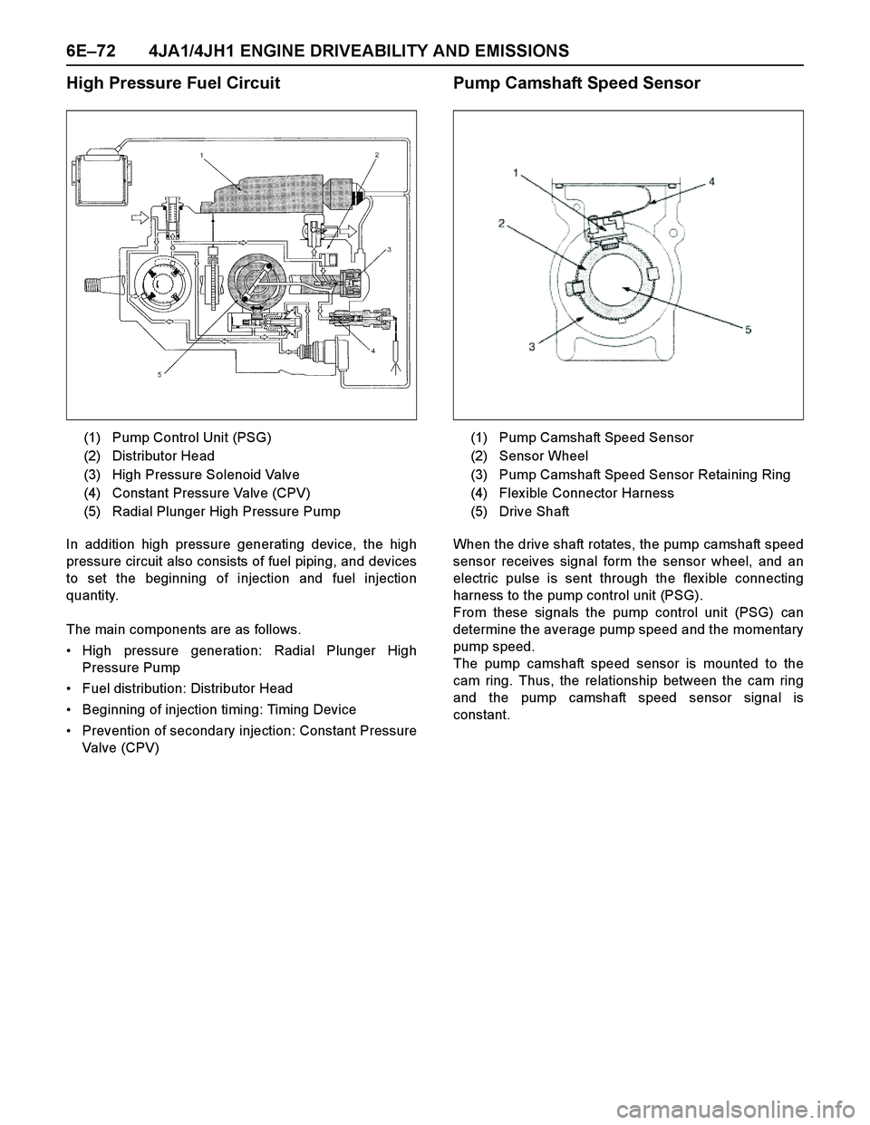
High Pressure Fuel Circuit
In addition high pressure generating device, the high
pressure circuit also consists of fuel piping, and devices
to set the beginning of injection and fuel injection
quantity.
The main components are as follows.
High pressure generation: Radial Plunger High
Pressure Pump
Fuel distribution: Distributor Head
Beginning of injection timing: Timing Device
Prevention of secondary injection: Constant Pressure
Valve (CPV)
Pump Camshaft Speed Sensor
When the drive shaft rotates, the pump camshaft speed
sensor receives signal form the sensor wheel, and an
electric pulse is sent through the flex ible connecting
harness to the pump control unit (PSG).
From these signals the pump control unit (PSG) can
determine the average pump speed and the momentary
pump speed.
The pump camshaft speed sensor is mounted to the
cam ring. Thus, the relationship between the cam ring
and the pump camshaft speed sensor signal is
constant. (1) Pump Control Unit (PSG)
(2) Distributor Head
(3) High Pressure Solenoid Valve
(4) Constant Pressure Valve (CPV)
(5) Radial Plunger High Pressure Pump
(1) Pump Camshaft Speed Sensor
(2) Sensor Wheel
(3) Pump Camshaft Speed Sensor Retaining Ring
(4) Flex ible Connector Harness
(5) Drive Shaft
Page 1451 of 4264
4JA1/4JH1 ENGINE DRIVEABILITY AND EMISSIONS 6E–79
–Are there areas subjected to vibration or
movement (engine, transmission or
suspension)?
–Are there areas ex posed to moisture, road salt
or other corrosives (battery acid, oil or other
fluids)?
–Are there common mounting areas with other
systems/components?
–Have previous repairs been performed to wiring,
connectors, components or mounting areas
(causing pinched wires between panels and
drivetrain or suspension components without
causing and immediate problem)?
–Does the vehicle have aftermarket or dealer-
installed equipment (radios, telephone, etc.)
Step 2: Isolate the problem
At this point, you should have a good idea of what could
cause the present condition, as well as could not cause
the condition. Actions to take include the following:
Divide (and separate, where possible) the system or
circuit into smaller sections
Confine the problem to a smaller area of the vehicle
(start with main harness connections while removing
panels and trim as necessary in order to eliminate
large vehicle sections from further investigation)
For two or more circuits that do not share a common
power or ground, concentrate on areas where
harnesses are routed together or connectors are
shared (refer to the following hints)
Hints
Though the symptoms may vary, basic electrical failures
are generally caused by:
Loose connections:
–Open/high resistance in terminals, splices,
connectors or grounds
Incorrect connector/harness routing (usually in new
vehicles or after a repair has been made):
–Open/high resistance in terminals, splices,
connectors of grounds
Corrosion and wire damage:
–Open/high resistance in terminals, splices,
connectors of grounds
Component failure:
–Opens/short and high resistance in relays,
modules, switches or loads
Aftermarket equipment affecting normal operation of
other systems
You may isolate circuits by:
Unplugging connectors or removing a fuse to
separate one part of the circuit from another part
Operating shared circuits and eliminating those that
function normally from the suspect circuit
If only one component fails to operate, begin testingat the component
If a number of components do no operate, begin tests
at the area of commonality (such as power sources,
ground circuits, switches or major connectors)
What resources you should use
Whenever appropriate, you should use the following
resources to assist in the diagnostic process:
Service manual
Technical equipment (for data analysis)
Ex perience
Technical Assistance
Circuit testing tools
5d. Intermittent Diagnosis
By definition, an intermittent problem is one that does
not occur continuously and will occur when certain
conditions are met. All these conditions, however, may
not be obvious or currently known. Generally,
intermittents are caused by:
Faulty electrical connections and wiring
Malfunctioning components (such as sticking relays,
solenoids, etc.)
EMI/RFI (Electromagnetic/radio frequency
interference)
Aftermarket equipment
Intermittent diagnosis requires careful analysis of
suspected systems to help prevent replacing good
parts. This may involve using creativity and ingenuity to
interpret customer complaints and simulating all
ex ternal and internal system conditions to duplicate the
problem.
What you should do
Step 1: A cquire information
A thorough and comprehensive customer check sheet
is critical to intermittent problem diagnosis. You should
require this, since it will dictate the diagnostic starting
point. The vehicle service history file is another
source for accumulating information about the
complaint.
Step 2: A nalyze the intermittent problem
Analyze the customer check sheet and service history
file to determine conditions relevant to the suspect
system(s).
Using service manual information, you must identify,
trace and locate all electrical circuits related to the
malfunctioning system(s). If there is more than one
system failure, you should identify, trace and locate
areas of commonality shared by the suspect circuits.
Page 1461 of 4264
4JA1/4JH1 ENGINE DRIVEABILITY AND EMISSIONS 6E–89
18 Brake Switch 2 Active/
InactiveInactive Inactive Inactive This displays operating status of the brake switch. This
should display "Active" when the brake pedal is stepped
on.
19 Clutch Sw itch Activ e /
InactiveInactive Inactive Inactive This displays operating status of the clutch switch. This
should display "Active" when the clutch pedal is stepped
on.
20 Neutra l Switch On/Off On On On This displa ys o pe rating status of the neutra l switch. This
should display "On" when the gear position is neutral.
21 A/C Informa tion
SwitchActive 12V/
Inactive 0VInactive 0V Inactive 0V Inactive 0V This displays the air conditioner request signal. This
should display "Active 12V" when the air conditioner switch
is switched on.
22 Dia gnostic Re quest Activ e 0V/
Inactive 12VIna ctiv e
12VInactive
12VIna ctiv e
12VThis display s the dia gnostic reque st signal. This sho uld
display "Inactive 12V" when the Tech 2 is connected.
23 System Voltage V 10 - 14 10 - 14 10 - 14 This displays the system voltage measured by the ECM at
ignition feed.
24 Ma in Re la y Activ e /
InactiveActive Active Active This displays operating status for the ECM main relay. This
should display "Active" when the key switch is turned on
and while engine is running.
25 Glow Time Relay Activ e 0V/
Inactive12VIna ctiv e
12VInactive
12VIna ctiv e
12VThis displays operating status for the glow relay. This
should display "Inactive 12V" when the engine is warm
uppe d.
26 Check Engine Light On/Off Off Off Off This displays operating status for the Check Engine Lamp.
This should display "On" when the Check Engine Lamp is
turned on.
27 Glow Time Telltale On/Off Off Off Off This displays operating status for the glow indicator lamp.
This sho uld display "On" whe n the glo w la mp is turne d o n.
28 Desired Engine Idle
Speedrpm 730 730 730 The desired engine idle speed that the ECM commanding.
The ECM compensates for various engine loads based on
engine coolant temperature.
29 A/C Re que st Activ e 0V/
Inactive 12VIna ctiv e
12VInactive
12VIna ctiv e
12VThis displays operating status of the A/C compressor. This
should display "Active 0V" when the compressor relay is
operated.
30 Immo bilize r Activ e /
InactiveInactive Inactive Inactive This should display "Inactive" when the immobilizer is
correctly operated.
31 Immo bilize r Signal Rece iv ed/
Not
Rece iv edNo t
Receive dNo t
Re ceive dNot
Re ce iv e dThis sho uld displa y "No t Receive d" whe n the immo bilize r is
not activated.
32 Immo bilize r Function
ProgrammedYes/ No Yes Yes Yes This should display "Yes" when the immobilizer is correctly
programmed.
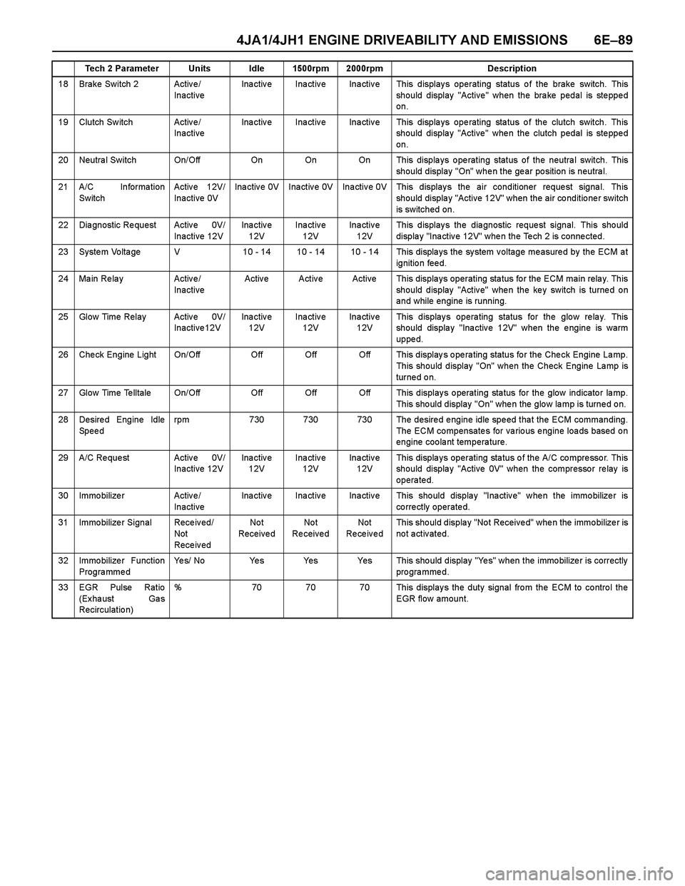
33 EGR Pulse Ratio
(Ex ha ust Ga s
Recirculatio n)% 70 70 70 This displays the duty signal from the ECM to control the
EGR flow amount. Tech 2 Parameter Units Idle 1500rpm 2000rpm Description