Page 1180 of 4264
6A – 40 ENGINE MECHANICAL
140R300001
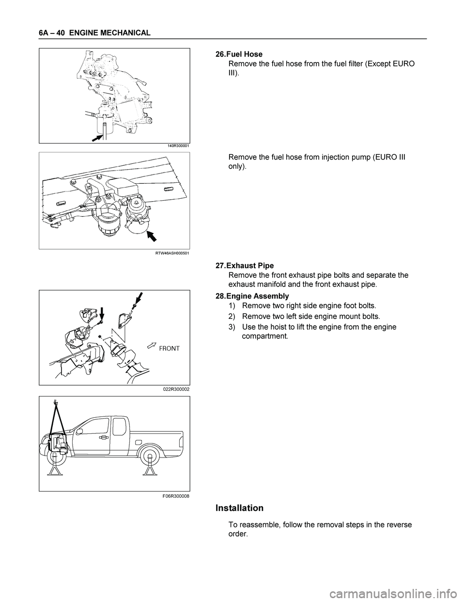
26. Fuel Hose
Remove the fuel hose from the fuel filter (Except EURO
III).
RTW46ASH000501
Remove the fuel hose from injection pump (EURO III
only).
27. Exhaust Pipe
Remove the front exhaust pipe bolts and separate the
exhaust manifold and the front exhaust pipe.
28. Engine Assembly
1) Remove two right side engine foot bolts.
2) Remove two left side engine mount bolts.
3) Use the hoist to lift the engine from the engine
compartment.
Installation
To reassemble, follow the removal steps in the reverse
order.
022R300002
F06R300008
Page 1183 of 4264
ENGINE MECHANICAL 6A – 43
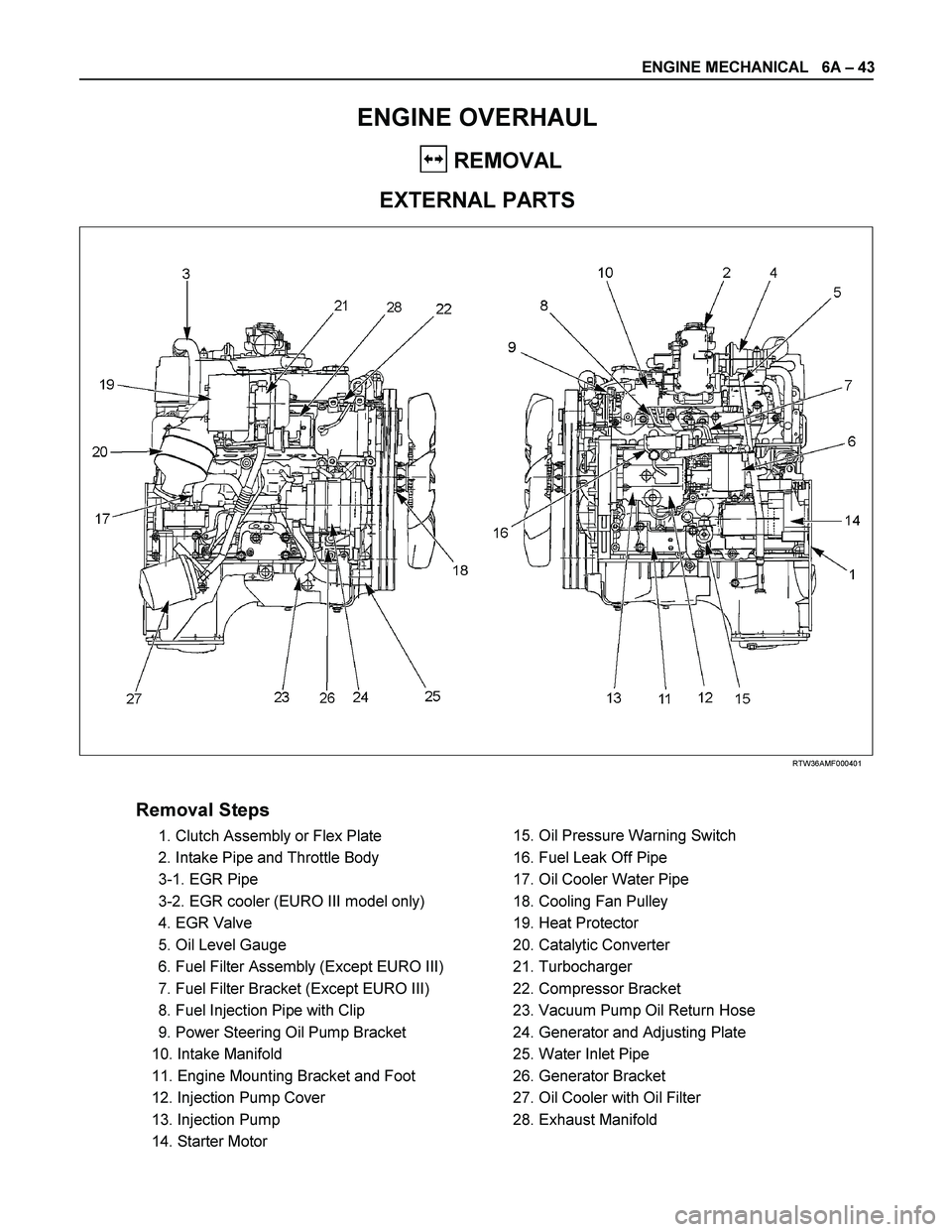
ENGINE OVERHAUL
REMOVAL
EXTERNAL PARTS
RTW36AMF000401
Removal Steps
1. Clutch Assembly or Flex Plate
2. Intake Pipe and Throttle Body
3-1. EGR Pipe
3-2. EGR cooler (EURO III model only)
4. EGR Valve
5. Oil Level Gauge
6. Fuel Filter Assembly (Except EURO III)
7. Fuel Filter Bracket (Except EURO III)
8. Fuel Injection Pipe with Clip
9. Power Steering Oil Pump Bracket
10. Intake Manifold
11. Engine Mounting Bracket and Foot
12. Injection Pump Cover
13. Injection Pump
14. Starter Motor
15. Oil Pressure Warning Switch
16. Fuel Leak Off Pipe
17. Oil Cooler Water Pipe
18. Cooling Fan Pulley
19. Heat Protector
20. Catalytic Converter
21. Turbocharger
22. Compressor Bracket
23. Vacuum Pump Oil Return Hose
24. Generator and Adjusting Plate
25. Water Inlet Pipe
26. Generator Bracket
27. Oil Cooler with Oil Filter
28. Exhaust Manifold
Page 1185 of 4264
ENGINE MECHANICAL 6A – 45
4JA1�L
RTW46ASH001001
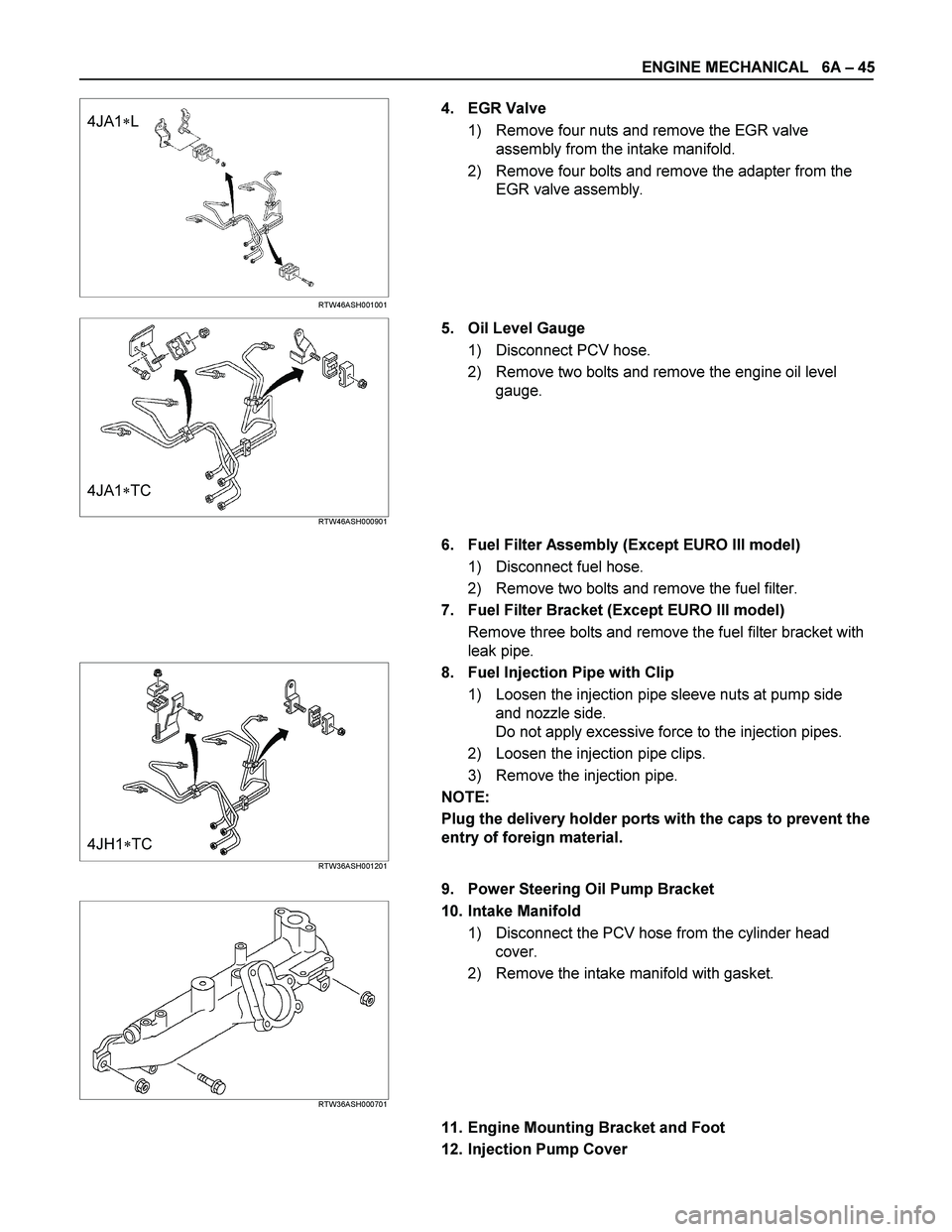
4. EGR Valve
1) Remove four nuts and remove the EGR valve
assembly from the intake manifold.
2) Remove four bolts and remove the adapter from the
EGR valve assembly.
4JA1�TC RTW46ASH000901
5. Oil Level Gauge
1) Disconnect PCV hose.
2) Remove two bolts and remove the engine oil level
gauge.
6. Fuel Filter Assembly (Except EURO III model)
1) Disconnect fuel hose.
2) Remove two bolts and remove the fuel filter.
7. Fuel Filter Bracket (Except EURO III model)
Remove three bolts and remove the fuel filter bracket with
leak pipe.
4JH1�TC RTW36ASH001201
8. Fuel Injection Pipe with Clip
1) Loosen the injection pipe sleeve nuts at pump side
and nozzle side.
Do not apply excessive force to the injection pipes.
2) Loosen the injection pipe clips.
3) Remove the injection pipe.
NOTE:
Plug the delivery holder ports with the caps to prevent the
entry of foreign material.
9. Power Steering Oil Pump Bracket
RTW36ASH000701
10. Intake Manifold
1) Disconnect the PCV hose from the cylinder head
cover.
2) Remove the intake manifold with gasket.
11. Engine Mounting Bracket and Foot
12. Injection Pump Cover
Page 1206 of 4264
6A – 66 ENGINE MECHANICAL
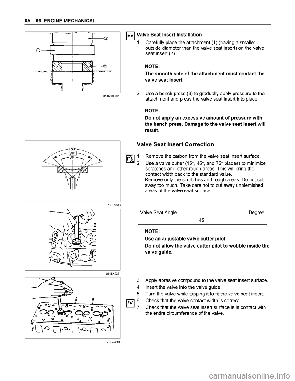
Valve Seat Insert Installation
1. Carefully place the attachment (1) (having a smaller
outside diameter than the valve seat insert) on the valve
seat insert (2).
NOTE:
The smooth side of the attachment must contact the
valve seat insert.
2. Use a bench press (3) to gradually apply pressure to the
attachment and press the valve seat insert into place.
NOTE:
Do not apply an excessive amount of pressure with
the bench press. Damage to the valve seat insert will
result.
Valve Seat Insert Correction
1. Remove the carbon from the valve seat insert surface.
2. Use a valve cutter (15�, 45�, and 75� blades) to minimize
scratches and other rough areas. This will bring the
contact width back to the standard value.
Remove only the scratches and rough areas. Do not cut
away too much. Take care not to cut away unblemished
areas of the valve seat surface.
Valve Seat Angle Degree
45
NOTE:
Use an adjustable valve cutter pilot.
Do not allow the valve cutter pilot to wobble inside the
valve guide.
3. Apply abrasive compound to the valve seat insert surface.
4. Insert the valve into the valve guide.
5. Turn the valve while tapping it to fit the valve seat insert.
6. Check that the valve contact width is correct.
7. Check that the valve seat insert surface is in contact with
the entire circumference of the valve.
011LX063 014RY00026
011LX037
011LX038
Page 1217 of 4264
ENGINE MECHANICAL 6A – 77
CAMSHAFT
Visually inspect the journals, the cams, the oil pump drive gear,
and the camshaft bearings for excessive wear and damage.
The camshaft and the camshaft bearings must be replaced if
these conditions are discovered during inspection.
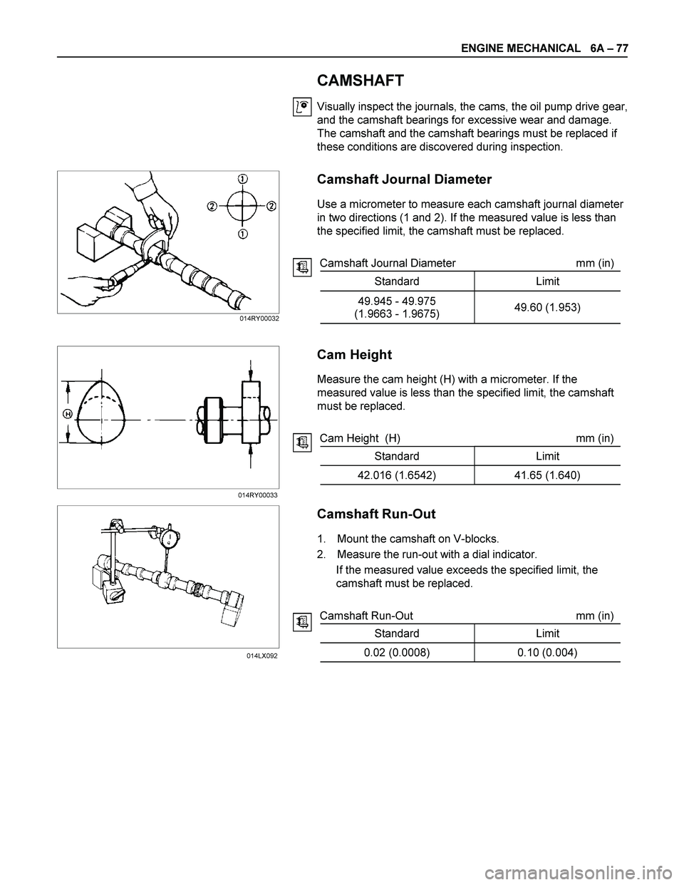
Camshaft Journal Diameter
Use a micrometer to measure each camshaft journal diameter
in two directions (1 and 2). If the measured value is less than
the specified limit, the camshaft must be replaced.
Camshaft Journal Diameter mm (in)
Standard Limit
49.945 - 49.975
(1.9663 - 1.9675) 49.60 (1.953)
Cam Height
Measure the cam height (H) with a micrometer. If the
measured value is less than the specified limit, the camshaft
must be replaced.
Cam Height (H) mm (in)
Standard Limit
42.016 (1.6542) 41.65 (1.640)
Camshaft Run-Out
1. Mount the camshaft on V-blocks.
2. Measure the run-out with a dial indicator.
If the measured value exceeds the specified limit, the
camshaft must be replaced.
Camshaft Run-Out mm (in)
Standard Limit
0.02 (0.0008) 0.10 (0.004)
014RY00032
014RY00033
014LX092
Page 1229 of 4264
ENGINE MECHANICAL 6A – 89
RTW36ASH001701
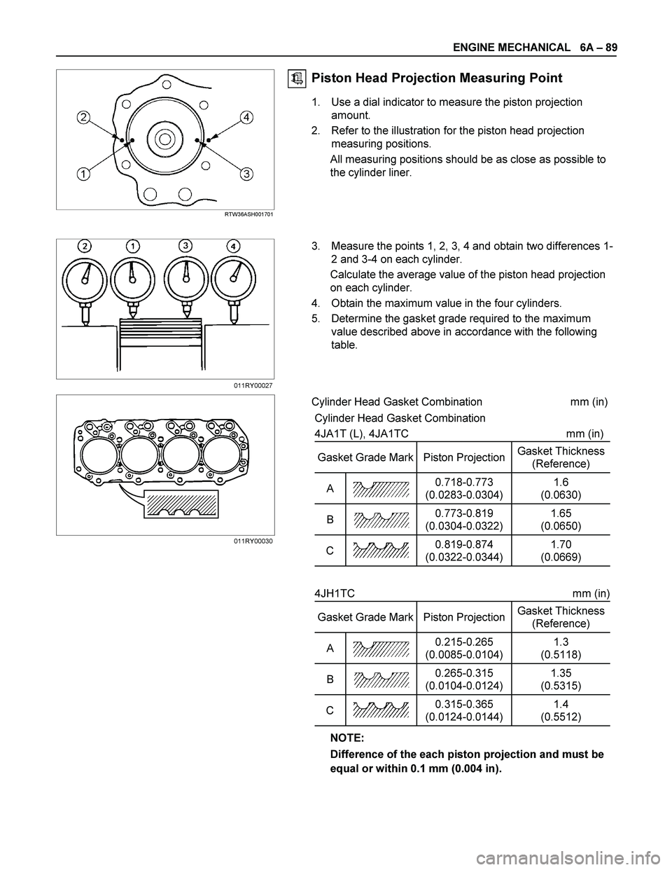
Piston Head Projection Measuring Point
1. Use a dial indicator to measure the piston projection
amount.
2. Refer to the illustration for the piston head projection
measuring positions.
All measuring positions should be as close as possible to
the cylinder liner.
3. Measure the points 1, 2, 3, 4 and obtain two differences 1-
2 and 3-4 on each cylinder.
Calculate the average value of the piston head projection
on each cylinder.
4. Obtain the maximum value in the four cylinders.
5. Determine the gasket grade required to the maximum
value described above in accordance with the following
table.
Cylinder Head Gasket Combination mm (in)
Cylinder Head Gasket Combination
4JA1T (L), 4JA1TC mm (in)
Gasket Grade Mark Piston Projection Gasket Thickness
(Reference)
A 0.718-0.773
(0.0283-0.0304) 1.6
(0.0630)
B 0.773-0.819
(0.0304-0.0322) 1.65
(0.0650)
C 0.819-0.874
(0.0322-0.0344) 1.70
(0.0669)
4JH1TC mm (in)
Gasket Grade Mark Piston Projection Gasket Thickness
(Reference)
A 0.215-0.265
(0.0085-0.0104) 1.3
(0.5118)
B 0.265-0.315
(0.0104-0.0124) 1.35
(0.5315)
C 0.315-0.365
(0.0124-0.0144) 1.4
(0.5512)
NOTE:
Difference of the each piston projection and must be
equal or within 0.1 mm (0.004 in).
011RY00027
011RY00030
Page 1255 of 4264
ENGINE MECHANICAL 6A – 115
RTW46ASH002201
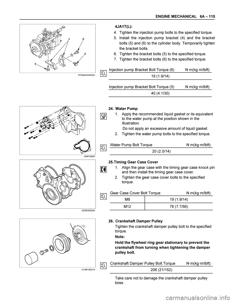
4JA1T(L):
4. Tighten the injection pump bolts to the specified torque.
5. Install the injection pump bracket (4) and the bracke
t
bolts (5) and (6) to the cylinder body. Temporarily tighten
the bracket bolts.
6. Tighten the bracket bolts (5) to the specified torque.
7. Tighten the bracket bolts (6) to the specified torque.
Injection pump Bracket Bolt Torque (6) N·m(kg·m/lbft)
19 (1.9/14)
Injection pump Bracket Bolt Torque (5) N·m(kg·m/lbft)
40 (4.1/30)
030RY00007
24. Water Pump
1. Apply the recommended liquid gasket or its equivalent
to the water pump at the position shown in the
illustration.
Do not apply an excessive amount of liquid gasket.
2. Tighten the water pump bolts to the specified torque.
Water Pump Bolt Torque N·m(kg·m/lbft)
20 (2.0/14)
25.Timing Gear Case Cover
1.
Align the gear case with the timing gear case knock pin
and then install the timing gear case cover.
2. Tighten the gear case cover bolts to the specified
torque.
Gear Case Cover Bolt Torque N·m(kg·m/lbft)
M8 19 (1.9/14)
M12 76 (7.7/56)
26. Crankshaft Damper Pulley
Tighten the crankshaft damper pulley bolt to the specified
torque.
Note:
Hold the flywheel ring gear stationary to prevent the
crankshaft from turning when tightening the damper
pulley bolt.
Crankshaft Damper Pulley Bolt Torque N·m(kg·m/lbft)
206 (21/152)
Take care not to damage the crankshaft damper pulley
boss.
014R100014 020R300004
Page 1258 of 4264
6A – 118 ENGINE MECHANICAL
INSTALLATION
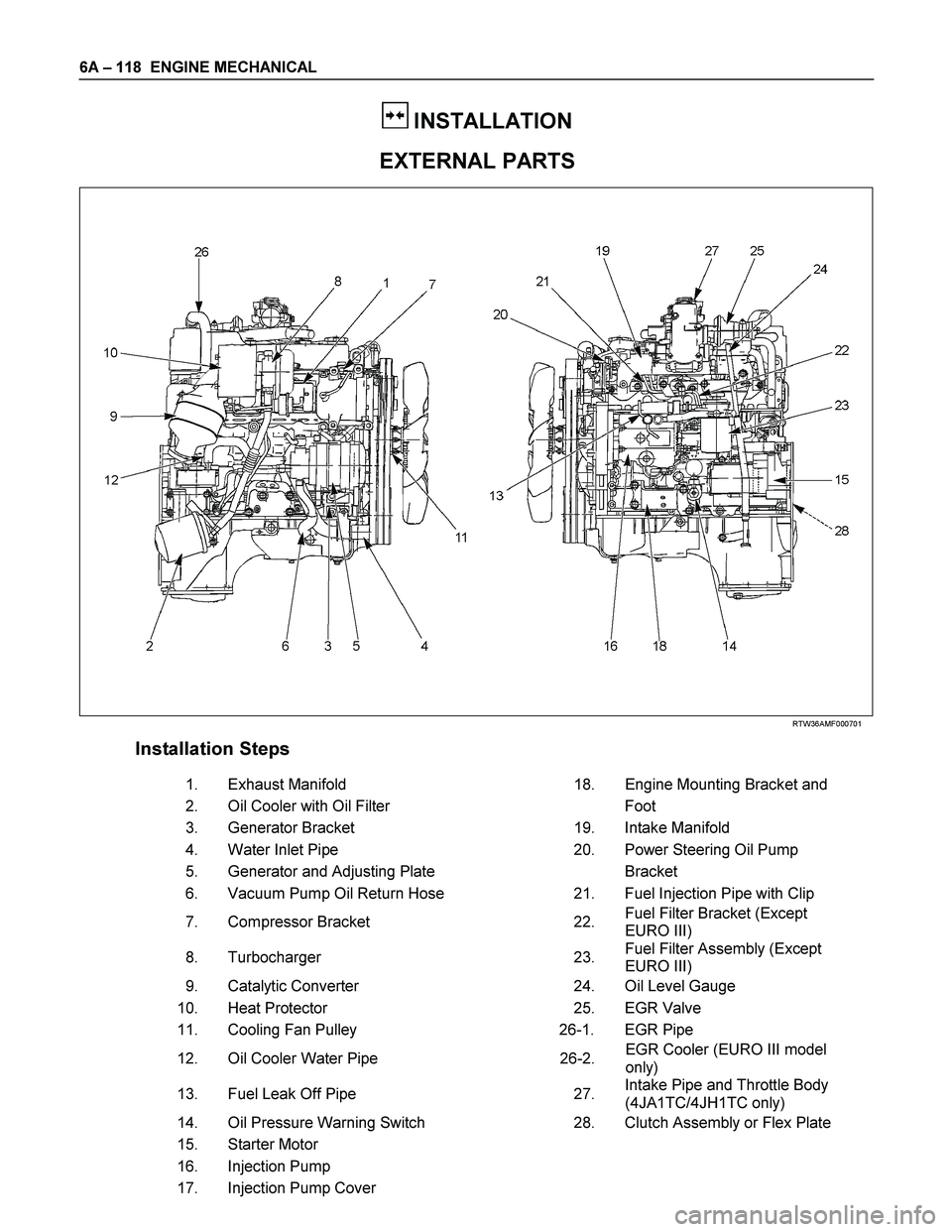
EXTERNAL PARTS
RTW36AMF000701
Installation Steps
1.
Exhaust Manifold 18. Engine Mounting Bracket and
2.
Oil Cooler with Oil Filter Foot
3. Generator Bracket 19. Intake Manifold
4. Water Inlet Pipe 20. Power Steering Oil Pump
5.
Generator and Adjusting Plate Bracket
6.
Vacuum Pump Oil Return Hose 21. Fuel Injection Pipe with Clip
7.
Compressor Bracket 22. Fuel Filter Bracket (Except
EURO III)
8. Turbocharger 23. Fuel Filter Assembly (Except
EURO III)
9. Catalytic Converter 24. Oil Level Gauge
10. Heat Protector 25. EGR Valve
11. Cooling Fan Pulley 26-1. EGR Pipe
12. Oil Cooler Water Pipe 26-2. EGR Cooler (EURO III model
only)
13. Fuel Leak Off Pipe 27. Intake Pipe and Throttle Body
(4JA1TC/4JH1TC only)
14. Oil Pressure Warning Switch 28. Clutch Assembly or Flex Plate
15. Starter Motor
16. Injection Pump
17. Injection Pump Cover