Page 4155 of 4264
ON-VEHICLE SERVICE (JR405E) 7A3-3
Cold Level
The vehicle must not have been driven so that the
temperature reaches around 20�C (68�F) before the
cold level check is made.
1. Park the vehicle on a level surface.
2. Apply the parking brake firmly.
3. Start the engine and allow it to warm up.
The engine coolant temperature gauge needle
should be midway between the “C” mark and “H”
mark.
4. Let the engine run at idle.
Move the select lever slowly through all the gea
r
ranges.
Stop in each range just long enough for the
transmission to engage.
5. Return the select lever either “P” or “N”.
6. Remove the ATF level dipstick.
7. Wipe the dipstick clean with a paper towel.
8. Reinsert the dipstick and wait several seconds.
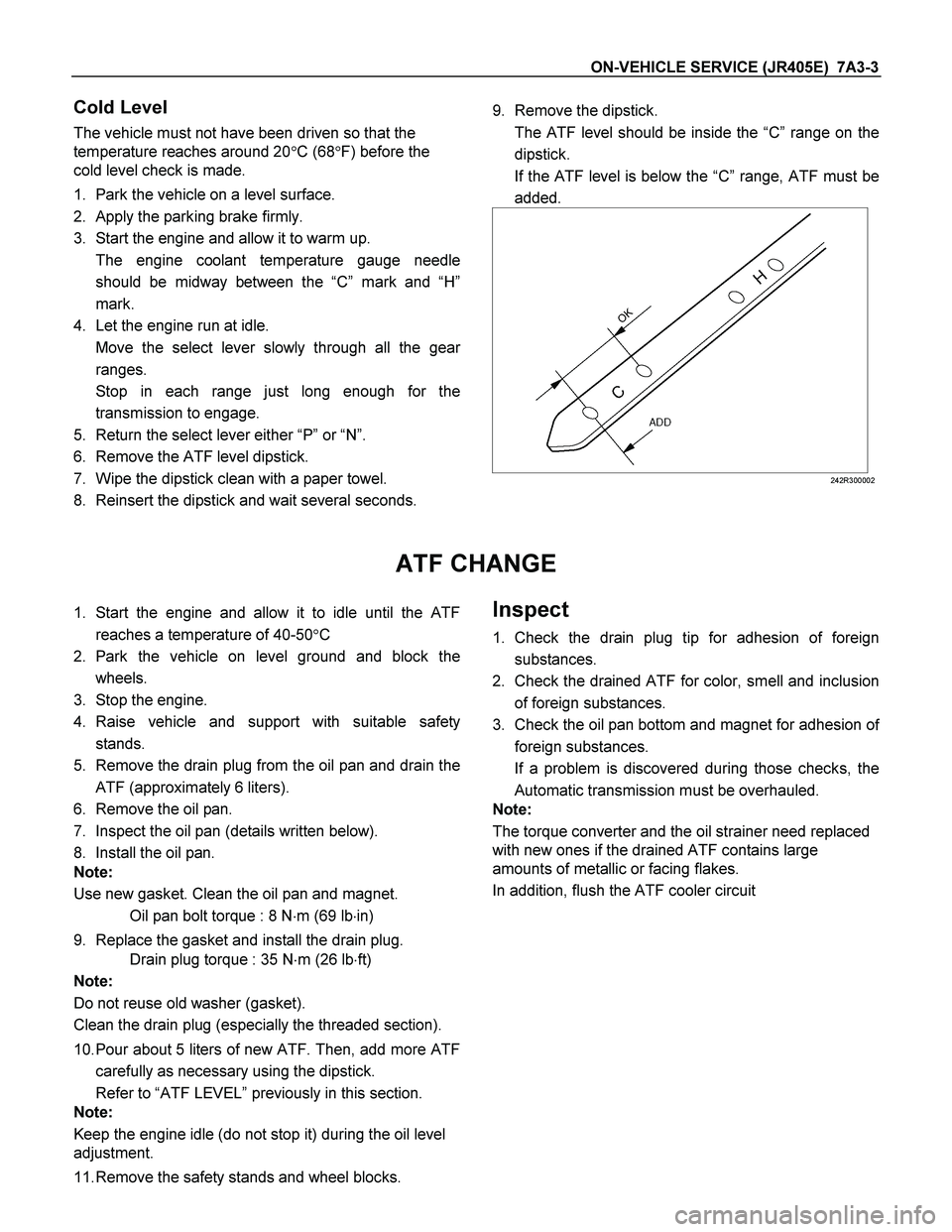
9. Remove the dipstick.
The ATF level should be inside the “C”range on the
dipstick.
If the ATF level is below the “C” range, ATF must be
added.
242R300002
ATF CHANGE
1. Start the engine and allow it to idle until the ATF
reaches a temperature of 40-50�C
2. Park the vehicle on level ground and block the
wheels.
3. Stop the engine.
4. Raise vehicle and support with suitable safety
stands.
5. Remove the drain plug from the oil pan and drain the
ATF (approximately 6 liters).
6. Remove the oil pan.
7. Inspect the oil pan (details written below).
8. Install the oil pan.
Note:
Use new gasket. Clean the oil pan and magnet.
Oil pan bolt torque : 8 N�m (69 lb�in)
9. Replace the gasket and install the drain plug.
Drain plug torque : 35 N�m (26 lb�ft)
Note:
Do not reuse old washer (gasket).
Clean the drain plug (especially the threaded section).
10. Pour about 5 liters of new ATF. Then, add more ATF
carefully as necessary using the dipstick.
Refer to “ATF LEVEL” previously in this section.
Note:
Keep the engine idle (do not stop it) during the oil level
adjustment.
11. Remove the safety stands and wheel blocks. Inspect
1. Check the drain plug tip for adhesion of foreign
substances.
2. Check the drained ATF for color, smell and inclusion
of foreign substances.
3. Check the oil pan bottom and magnet for adhesion o
f
foreign substances.
If a problem is discovered during those checks, the
Automatic transmission must be overhauled.
Note:
The torque converter and the oil strainer need replaced
with new ones if the drained ATF contains large
amounts of metallic or facing flakes.
In addition, flush the ATF cooler circuit
Page 4171 of 4264
ON-VEHICLE SERVICE (JR405E) 7A3-19
Install or Connect
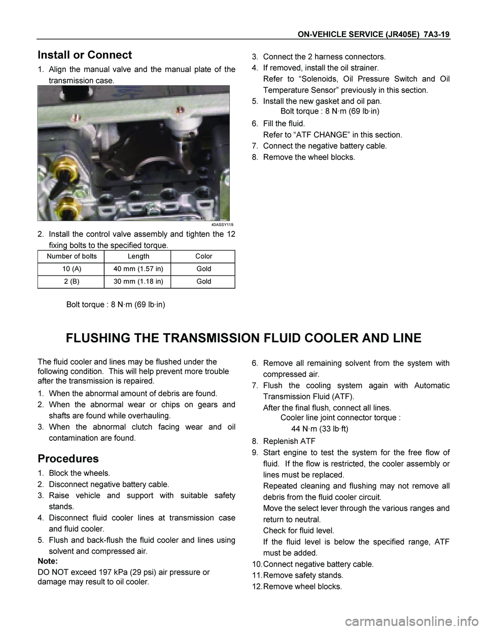
1. Align the manual valve and the manual plate of the
transmission case.
43ASSY119
2. Install the control valve assembly and tighten the 12
fixing bolts to the specified torque.
Number of bolts Length Color
10 (A) 40 mm (1.57 in) Gold
2 (B) 30 mm (1.18 in) Gold
Bolt torque : 8 N·m (69 lb·in)
3. Connect the 2 harness connectors.
4. If removed, install the oil strainer.
Refer to “Solenoids, Oil Pressure Switch and Oil
Temperature Sensor” previously in this section.
5. Install the new gasket and oil pan.
Bolt torque : 8 N·m (69 lb·in)
6. Fill the fluid.
Refer to “ATF CHANGE” in this section.
7. Connect the negative battery cable.
8. Remove the wheel blocks.
FLUSHING THE TRANSMISSION FLUID COOLER AND LINE
The fluid cooler and lines may be flushed under the
following condition. This will help prevent more trouble
after the transmission is repaired.
1. When the abnormal amount of debris are found.
2. When the abnormal wear or chips on gears and
shafts are found while overhauling.
3. When the abnormal clutch facing wear and oil
contamination are found.
Procedures
1. Block the wheels.
2. Disconnect negative battery cable.
3. Raise vehicle and support with suitable safety
stands.
4. Disconnect fluid cooler lines at transmission case
and fluid cooler.
5. Flush and back-flush the fluid cooler and lines using
solvent and compressed air.
Note:
DO NOT exceed 197 kPa (29 psi) air pressure or
damage may result to oil cooler.
6. Remove all remaining solvent from the system with
compressed air.
7. Flush the cooling system again with Automatic
Transmission Fluid (ATF).
After the final flush, connect all lines.
Cooler line joint connector torque :
44 N·m (33 lb·ft)
8. Replenish ATF
9. Start engine to test the system for the free flow o
f
fluid. If the flow is restricted, the cooler assembly o
r
lines must be replaced.
Repeated cleaning and flushing may not remove all
debris from the fluid cooler circuit.
Move the select lever through the various ranges and
return to neutral.
Check for fluid level.
If the fluid level is below the specified range, ATF
must be added.
10. Connect negative battery cable.
11. Remove safety stands.
12. Remove wheel blocks.
Page 4173 of 4264
ON-VEHICLE SERVICE (JR405E) 7A3-21
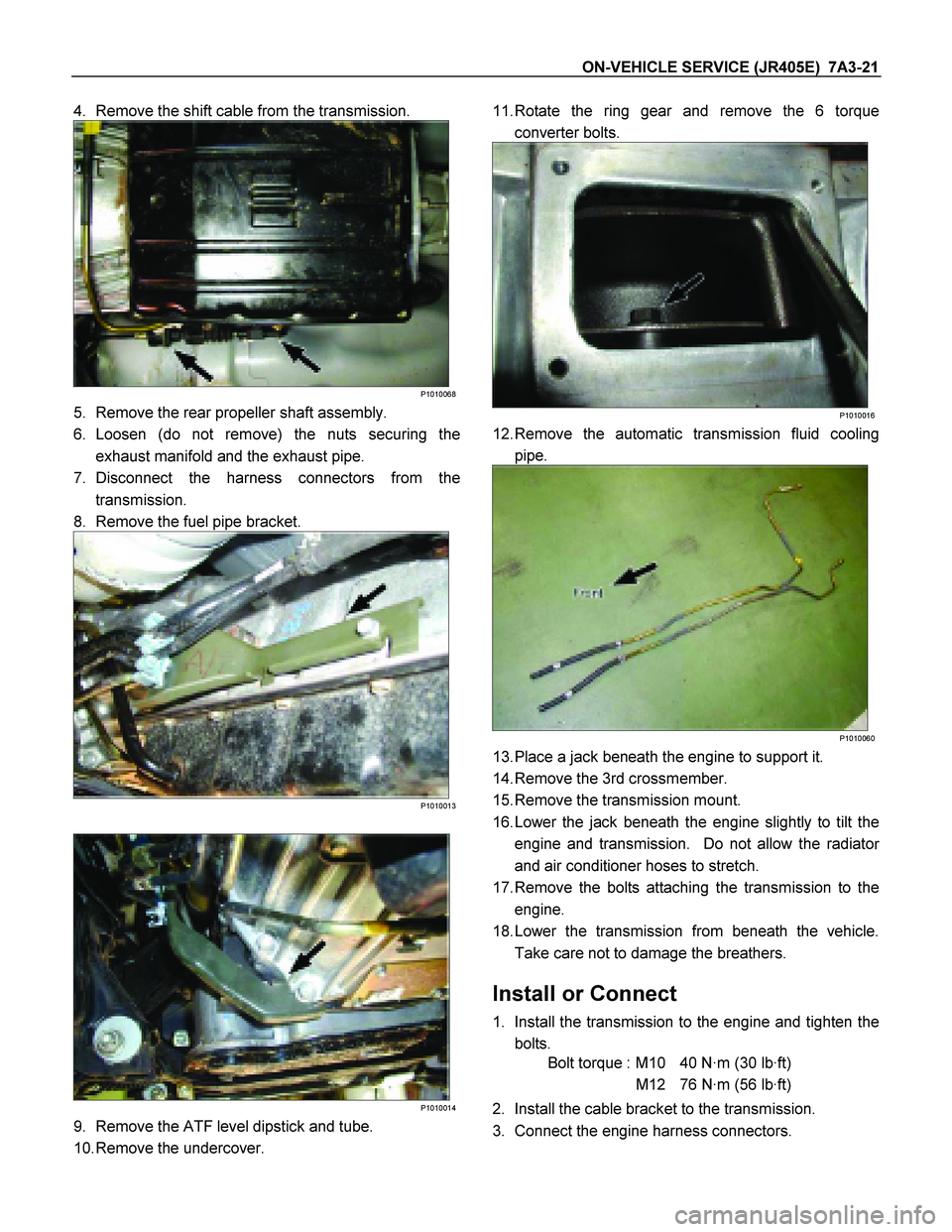
4. Remove the shift cable from the transmission.
P1010068
5. Remove the rear propeller shaft assembly.
6. Loosen (do not remove) the nuts securing the
exhaust manifold and the exhaust pipe.
7. Disconnect the harness connectors from the
transmission.
8. Remove the fuel pipe bracket.
P1010013
P1010014
9. Remove the ATF level dipstick and tube.
10. Remove the undercover.
11. Rotate the ring gear and remove the 6 torque
converter bolts.
P1010016
12. Remove the automatic transmission fluid cooling
pipe.
P1010060
13. Place a jack beneath the engine to support it.
14. Remove the 3rd crossmember.
15. Remove the transmission mount.
16. Lower the jack beneath the engine slightly to tilt the
engine and transmission. Do not allow the radiato
r
and air conditioner hoses to stretch.
17. Remove the bolts attaching the transmission to the
engine.
18. Lower the transmission from beneath the vehicle.
Take care not to damage the breathers.
Install or Connect
1. Install the transmission to the engine and tighten the
bolts.
Bolt torque : M10 40 N·m (30 lb·ft)
M12 76 N·m (56 lb·ft)
2. Install the cable bracket to the transmission.
3. Connect the engine harness connectors.