Page 3769 of 4264
ON-VEHICLE SERVICE (AW30 –40LE) 7A3-13
Measure Stall Speed
1. Chock the four wheels.
2. Mount an engine tachometer.
3. Fully apply the parking brake.
4. Step down strongly on the brake pedal with your left foot.
5. Start the engine.
6. Turn off the A/C.
7. Shift into the “D" range. Step all the way down on
the accelerator pedal with your right foot. Quickl
y
read the highest engine rpm.
Stall speed: 2100 �
� �
�
150 rpm
8. Perform the same test in the “R" range.
Evaluation
1. If the engine speed is the same for both ranges but
lower than the specified value:
Engine output is insufficient.
Stator one-way clutch is not operating properly.
NOTE: If more than 600 rpm below the specified value,
the torque converter could be faulty.
2. If the stall speed in “D" range is higher than
specified:
Line pressure too low
Forward clutch slipping
No.2 one-way clutch not operating properly
3. If the stall speed in “R" range is higher than
specified:
Line pressure too low
Direct clutch slipping
No.3 brake slipping
4. If the stall speed in the “R" and “D" ranges are
higher than specified:
Line pressure too low
Improper fluid level
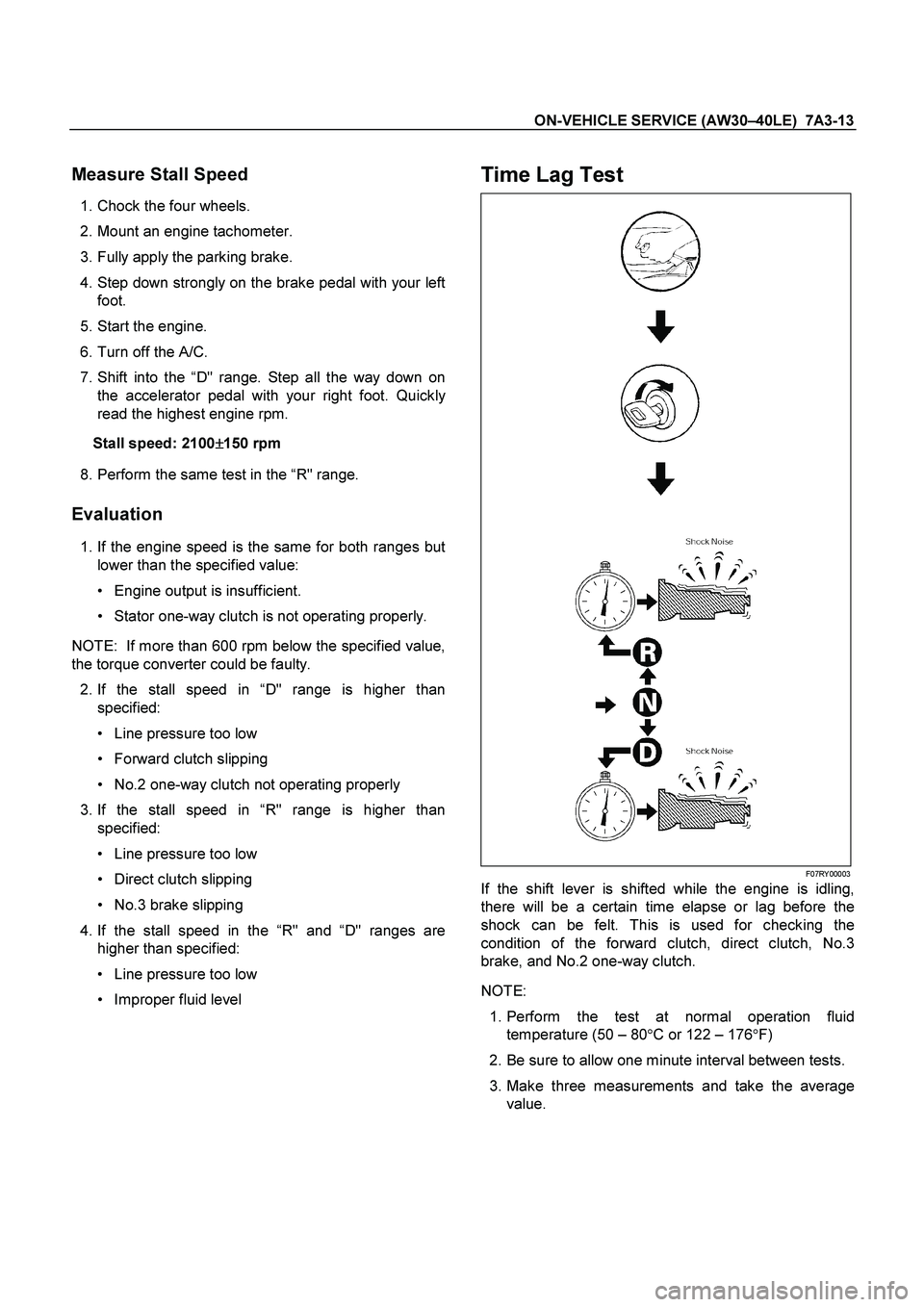
Time Lag Test
F07RY00003
If the shift lever is shifted while the engine is idling,
there will be a certain time elapse or lag before the
shock can be felt. This is used for checking the
condition of the forward clutch, direct clutch, No.3
brake, and No.2 one-way clutch.
NOTE:
1. Perform the test at normal operation fluid
temperature (50 – 80 �C or 122 – 176 �F)
2. Be sure to allow one minute interval between tests.
3. Make three measurements and take the average value.
Page 3770 of 4264
7A3-14 ON-VEHICLE SERVICE (AW30 –40LE)
Measure Time Lag
1. Fully apply the parking brake.
2. Start the engine. Check idling speed (A/C OFF).
3. Shift the shift lever from “N" to “D" range. Using a
stopwatch, measure the time it takes from shifting
the lever until the shock is felt.
Time lag: Less than 0.7 seconds
4. In same manner, measure the time lag for “N"
�
“R".
Time lag: Less than 1.2 seconds
Evaluation
1. If “N" �
“ D" time lag is longer than specified:
Line pressure too low
Forward clutch malfunction
No.2 one-way clutch not operating properly
2. If “N" �
“ R" time lag is longer than specified:
Line pressure too low
Direct clutch malfunction
No.3 brake malfunction
3. If both time lag is longer than specified:
Line pressure too low
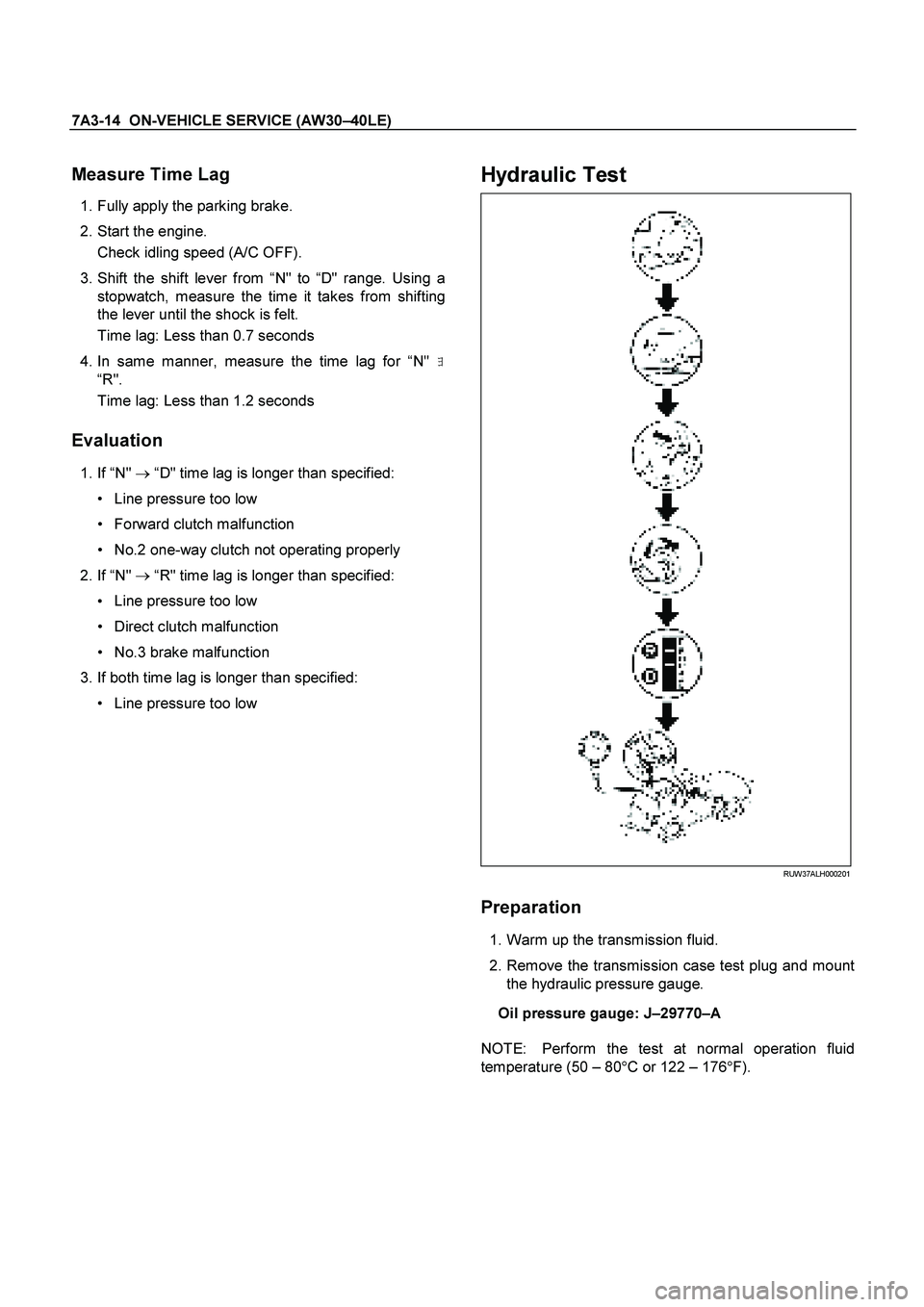
Hydraulic Test
RUW37ALH000201
Preparation
1. Warm up the transmission fluid.
2. Remove the transmission case test plug and mount the hydraulic pressure gauge.
Oil pressure gauge: J –29770 –A
NOTE: Perform the test at normal operation fluid
temperature (50 – 80 �
C or 122 – 176 �
F).
Page 3791 of 4264
ON-VEHICLE SERVICE (AW30 –40LE) 7A3-35
Shift Solenoid and Lock-Up Solenoid
Removal
Preparation:
Disconnect negative ( –) battery cable.
Drain the fluid.
Refer to ATF REPLACEMENT in this section.
1. Remove oil lever gage and oil filler tube.
2. Support transfer case (4
�4) or rear cover (4�2)
with a transmission jack.
3. Remove engine rear mounting nuts.
F07RW008
4. Remove fule pipe heat protector on tansmission
corssmenber.
5. Remove fuel pipe from the crossmenber.
6. Remove transmission crossmenber.
7. Remove the nineteen bolts.
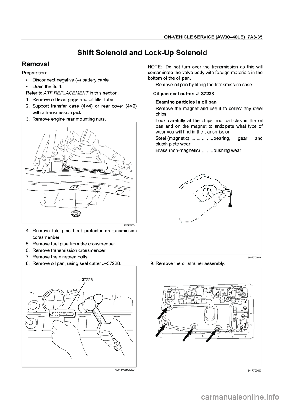
8. Remove oil pan, using seal cutter J –37228.
RUW37ASH002901
NOTE: Do not turn over the transmission as this will
contaminate the valve body with foreign materials in the
bottom of the oil pan.
Remove oil pan by lifting the transmission case.
Oil pan seal cutter: J –37228
Examine particles in oil pan
Remove the magnet and use it to collect any steel
chips.
Look carefully at the chips and particles in the oil
pan and on the magnet to anticipate what type o
f
wear you will find in the transmission:
Steel (magnetic) ..................bearing, gear and
clutch plate wear
Brass (non-magnetic) ..........bushing wear
240RY00008
9. Remove the oil strainer assembly.
244RY00003
Page 3801 of 4264
ON-VEHICLE SERVICE (AW30 –40LE) 7A3-45
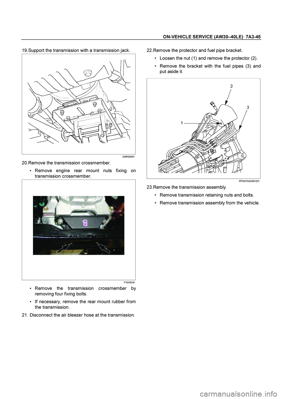
19.Support the transmission with a transmission jack.
220RS0001
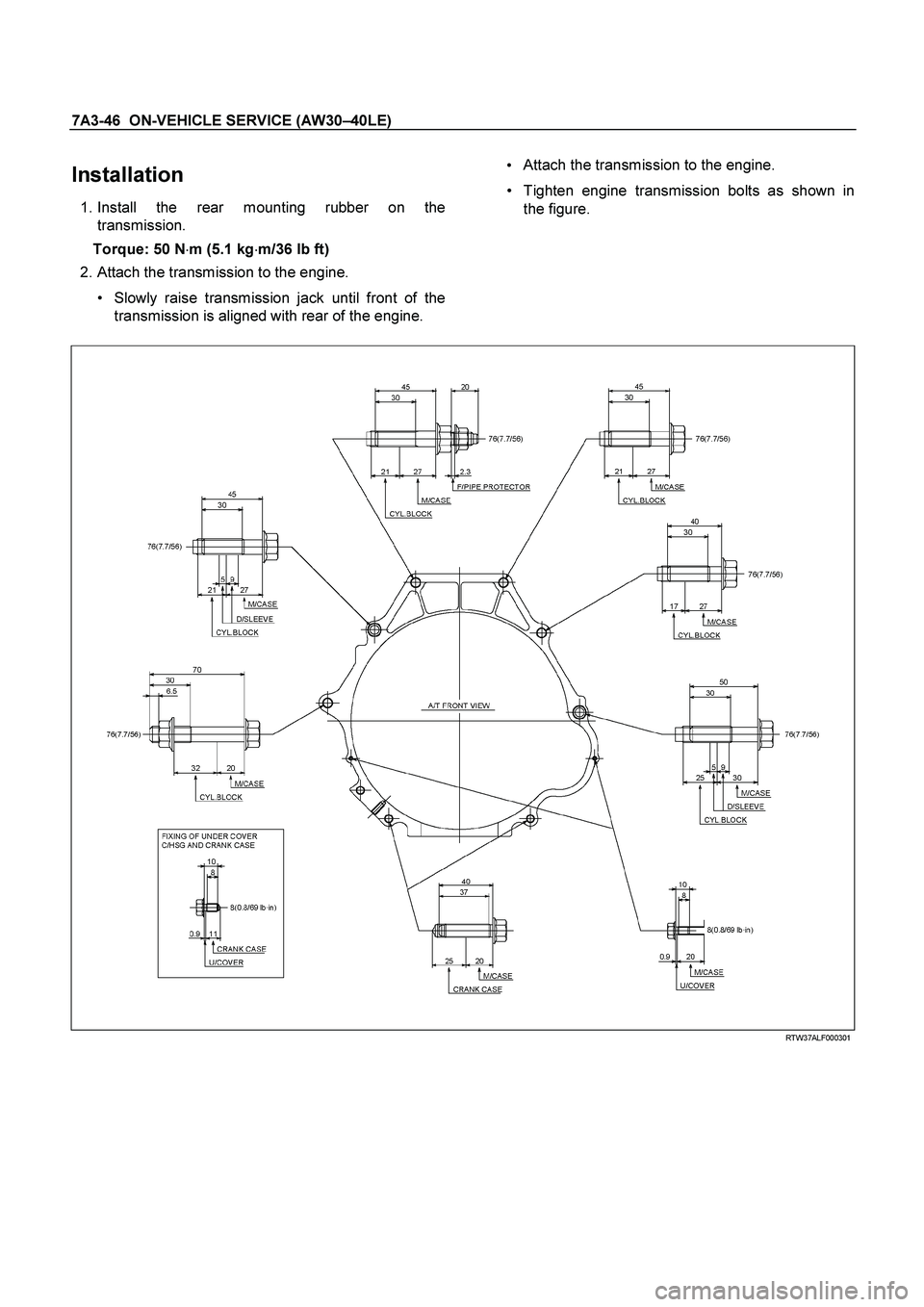
20.Remove the transmission crossmember.
Remove engine rear mount nuts fixing on
transmission crossmember.
P1010018
Remove the transmission crossmember by
removing four fixing bolts.
If necessary, remove the rear mount rubber from
the transmission.
21. Disconnect the air bleezer hose at the transmission.
22.Remove the protector and fuel pipe bracket.
Loosen the nut (1) and remove the protector (2).
Remove the bracket with the fuel pipes (3) and
put aside it.
RTW37ASH001201
23.Remove the transmission assembly.
Remove transmission retaining nuts and bolts.
Remove transmission assembly from the vehicle.
Page 3802 of 4264
7A3-46 ON-VEHICLE SERVICE (AW30 –40LE)
Installation
1. Install the rear mounting rubber on the
transmission.
Torque: 50 N �m (5.1 kg �m/36 lb ft)
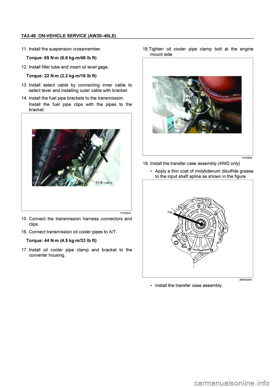
2. Attach the transmission to the engine.
Slowly raise transmission jack until front of the
transmission is aligned with rear of the engine.
Attach the transmission to the engine.
Tighten engine transmission bolts as shown in
the figure.
RTW37ALF000301
Page 3803 of 4264
ON-VEHICLE SERVICE (AW30 –40LE) 7A3-47
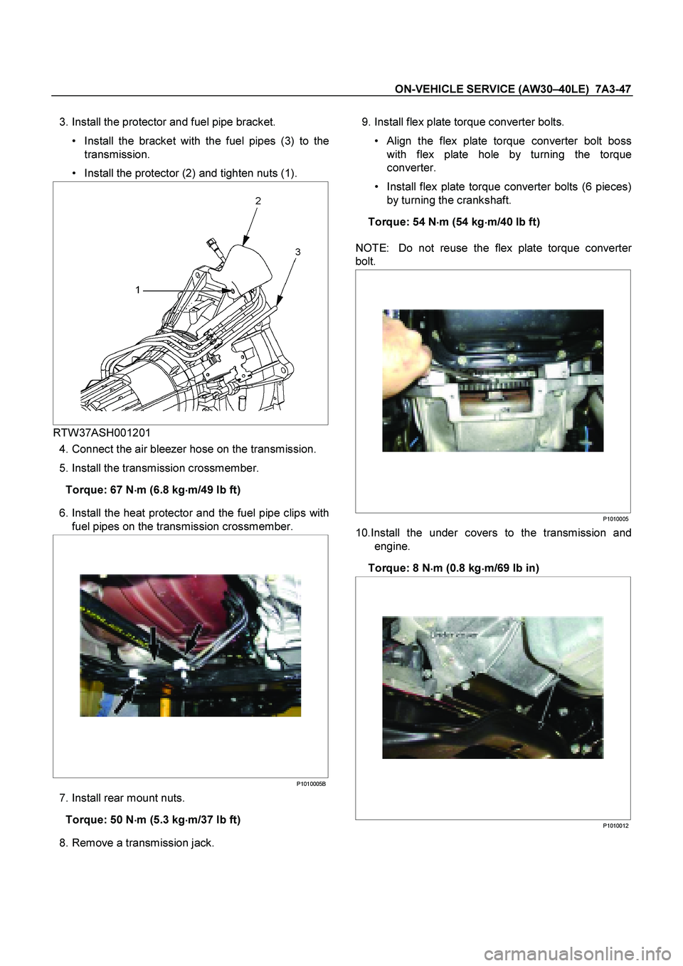
3. Install the protector and fuel pipe bracket.
Install the bracket with the fuel pipes (3) to the
transmission.
Install the protector (2) and tighten nuts (1).
RTW37ASH001201
4. Connect the air bleezer hose on the transmission.
5. Install the transmission crossmember.
Torque: 67 N �
��
�
m (6.8 kg �
��
�
m/49 lb ft)
6. Install the heat protector and the fuel pipe clips with
fuel pipes on the transmission crossmember.
P1010005B
7. Install rear mount nuts.
Torque: 50 N �
��
�
m (5.3 kg
�
��
�
m/37 lb ft)
8. Remove a transmission jack.
9. Install flex plate torque converter bolts.
Align the flex plate torque converter bolt boss
with flex plate hole by turning the torque
converter.
Install flex plate torque converter bolts (6 pieces)
by turning the crankshaft.
Torque: 54 N �
��
�
m (54 kg
�
��
�
m/40 lb ft)
NOTE: Do not reuse the flex plate torque converte
r
bolt.
P1010005
10.Install the under covers to the transmission and
engine.
Torque: 8 N �
��
�
m (0.8 kg
�
��
�
m/69 lb in)
P1010012
Page 3804 of 4264
7A3-48 ON-VEHICLE SERVICE (AW30 –40LE)
11. Install the suspension crossmember.
Torque: 65 N �
��
�
m (6.6 kg �
��
�
m/48 lb ft)
12. Install filler tube and insert oil level gage.
Torque: 22 N �
��
�
m (2.2 kg �
��
�
m/16 lb ft)
13. Install select cable by connecting inner cable to
select lever and installing outer cable with bracket.
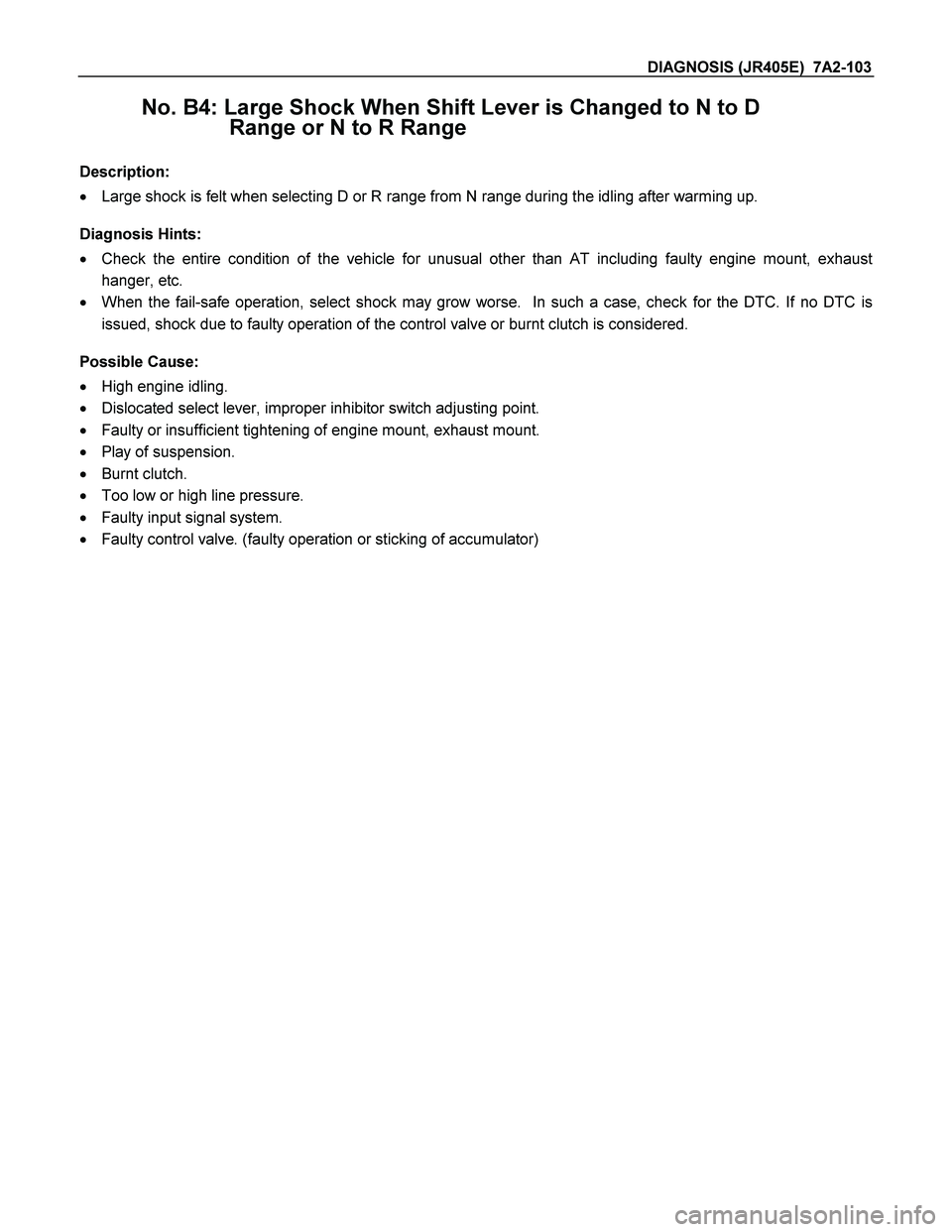
14. Install the fuel pipe brackets to the transmission. Install the fuel pipe clips with the pipes to the
bracket.
P1010010
15. Connect the transmission harness connectors and
clips.
16. Connect transmission oil cooler pipes to A/T.
Torque: 44 N �
��
�
m (4.5 kg
�
��
�
m/33 lb ft)
17. Install oil cooler pipe clamp and bracket to the
converter housing.
18.Tighten oil cooler pipe clamp bolt at the engine
mount side.
P1010024
19. Install the transfer case assembly.(4WD only)
Apply a thin coat of molybdenum disulfide grease
to the input shaft spline as shown in the figure.
260R300001
Install the transfer case assembly.
Page 4095 of 4264
DIAGNOSIS (JR405E) 7A2-103
No. B4: Large Shock When Shift Lever is Changed to N to D
Range or N to R Range
Description:
� Large shock is felt when selecting D or R range from N range during the idling after warming up.
Diagnosis Hints:
� Check the entire condition of the vehicle for unusual other than AT including faulty engine mount, exhaust
hanger, etc.
� When the fail-safe operation, select shock may grow worse. In such a case, check for the DTC. If no DTC is
issued, shock due to faulty operation of the control valve or burnt clutch is considered.
Possible Cause:
� High engine idling.
� Dislocated select lever, improper inhibitor switch adjusting point.
� Faulty or insufficient tightening of engine mount, exhaust mount.
� Play of suspension.
� Burnt clutch.
� Too low or high line pressure.
� Faulty input signal system.
� Faulty control valve. (faulty operation or sticking of accumulator)