Page 376 of 4264
5A-60 BRAKE CONTROL SYSTEM
DTC C0233 (Flash Code 33) Rear Right Wheel Speed Sensor Signal - Tooth
Chipping
LTW35AMF000101
Step Action
Value(s) Yes No
1 Was the “Basic Diagnostic Flow Chart” performed?
- Go to Step 2 Go to Basic
Diagnostic
Flow Chart
2 1. Check for a poor connection at the rear right wheel
speed sensor harness connector.
2. Check installation condition for rear right wheel
speed sensor.
3. If a problem is found, repair as necessary.
Was a problem found?
- Verify repair Go to Step 3
3 1. Check condition for sensor rotor at rear axle.
2. If a problem is found, repair as necessary.
Was a problem found?
- Verify repair Go to Step 4
4 1. Ignition “OFF,” disconnect the EHCU and rear right
wheel speed sensor.
2. Check the circuit between EHCU and rear right
wheel speed sensor. (short to ground, or short to
voltage.)
3. If a problem is found, repair as necessary.
Was a problem found?
- Verify repair Go to Step 5
Page 381 of 4264
BRAKE CONTROL SYSTEM 5A-65
Step Action
Value(s) Yes No
5 Repair or replace the rear left sensor rotor at rear
axle.
Was the action complete? - Verify repair
Go to Step 6 -
6 Select “Display DTCs” with the Tech 2.
Note : Perform the various tests (actuator test, test
run, brake test, etc.) then observe the DTC with a
Tech2.
Are any DTCs stored? - Go to Step 7 Verify repair
7 Replace EHCU.
Note : Check the EHCU type for specification, when
the EHCU is replaced.
(Specification ; 2WD model or 4WD model)
Was the action complete? - Verify repair -
Page 382 of 4264
5A-66 BRAKE CONTROL SYSTEM
DTC C0237 (Flash Code 37) Rear Left Wheel Speed Sensor Signal - Tooth
Chipping
LTW35AMF000101
Step Action
Value(s) Yes No
1 Was the “Basic Diagnostic Flow Chart” performed?
- Go to Step 2 Go to Basic
Diagnostic
Flow Chart
2 1. Check for a poor connection at the rear left wheel
speed sensor harness connector.
2. Check installation condition for rear left wheel
speed sensor.
3. If a problem is found, repair as necessary.
Was a problem found?
- Verify repair Go to Step 3
3 1. Check condition for sensor rotor at rear axle.
2. If a problem is found, repair as necessary.
Was a problem found?
- Verify repair Go to Step 4
4 1. Ignition “OFF,” disconnect the EHCU and rear left
wheel speed sensor.
2. Check the circuit between EHCU and rear left
wheel speed sensor. (short to ground, or short to
voltage.)
3. If a problem is found, repair as necessary.
Was a problem found?
- Verify repair Go to Step 5
Page 396 of 4264
5A-80 BRAKE CONTROL SYSTEM
DTC C0274 (Flash Code 74) ABS Operation Long Time
RTW45AMF000201
Step Action
Value(s) Yes No
1 Was the “Basic Diagnostic Flow Chart” performed?
- Go to Step 2 Go to Basic
Diagnostic
Flow Chart
2 Was the “Basic Inspection Procedure” performed?
- Go to Step 3 Go to Basic
Inspection
Procedure
3 1. Check for a poor connection at the wheel speed
sensor harness connector.
2. Check installation condition for wheel speed
sensor.
3. If a problem is found, repair as necessary.
Was a problem found? - Verify repair Go to Step 4
4 1. Check condition for sensor rotor.
2. If a problem is found, repair as necessary.
Was a problem found? - Verify repair Go to Step 5
5 1. Ignition “OFF,” disconnect the EHCU and wheel
speed sensor.
2. Check the circuit between EHCU and wheel speed
sensor.(short ground, or short to voltage.)
3. If a problem is found, repair as necessary.
Was a problem found? - Verify repair Go to Step 6
Page 407 of 4264

ANTI-LOCK BRAKE SYSTEM 5B-1
SECTION 5B
BRAKES
ANTI-LOCK BRAKE SYSTEM
TABLE OF CONTENTS
PAGE
Service Precaution ...................................................................................................................... 5B – 2
Torque Specifications ................................................................................................................ 5B – 3
Electronic Hydraulic Control Unit ........................................................................................... 5B – 7
Electronic Hydraulic Control Unit and Associated Parts ............................................ 5B – 7
Removal .................................................................................................................................... 5B – 7
Installation ................................................................................................................................ 5B – 7
Front Wheel Speed Sensor ....................................................................................................... 5B – 8
Front Wheel Speed Sensor and Associated Parts ........................................................ 5B – 8
Removal .................................................................................................................................... 5B – 9
Inspection and Repair ........................................................................................................... 5B – 9
Installation ................................................................................................................................ 5B – 10
Rear Wheel Speed Sensor ........................................................................................................ 5B – 11
Rear Wheel Sensor and Associated Parts ....................................................................... 5B – 11
Removal .................................................................................................................................... 5B – 11
Inspection and Repair ........................................................................................................... 5B – 11
Installation ................................................................................................................................ 5B – 12
Front Speed Sensor Rotor ........................................................................................................ 5B – 13
Front Sensor Rotor and Associated Parts ....................................................................... 5B – 13
Removal .................................................................................................................................... 5B – 13
Inspection and Repair ........................................................................................................... 5B – 14
Installation ................................................................................................................................ 5B – 14
Rear Speed Sensor Rotor .......................................................................................................... 5B – 16
Rear Sensor Rotor and Associated Parts ........................................................................ 5B – 16
Removal .................................................................................................................................... 5B – 16
Inspection and Repair ........................................................................................................... 5B – 17
Installation ................................................................................................................................ 5B – 17
G-Sensor ........................................................................................................................................ 5B – 19
G-Sensor and Associated Parts ......................................................................................... 5B – 19
Page 419 of 4264
ANTI-LOCK BRAKE SYSTEM 5B-13
Front Speed Sensor Rotor
Front Sensor Rotor and Associated Parts
411R300010
Legend
1.
Sensor Rotor
2.
Hub and Disc
3.
Disc Rotor fixing Bolt
4. Hub and Disc Assembly
Removal
1. Remove the hub and disc assembly (4). (Refer to
the section Front wheel Drive).
2. Remove two disc rotor fixing bolts (3) on a diagonal.
3. Drive out the sensor rotor using a metal bar and
hammer through the two bolt holes.
�
Discard the used sensor rotor.
4. Install disc rotot fixing bolts and tighten them to the
specified torque.
Torque : 103 N�
m (10.5 kg�
m /76 lb ft)
Page 420 of 4264
5B -14 ANTI-LOCK BRAKE SYSTEM
411R300007
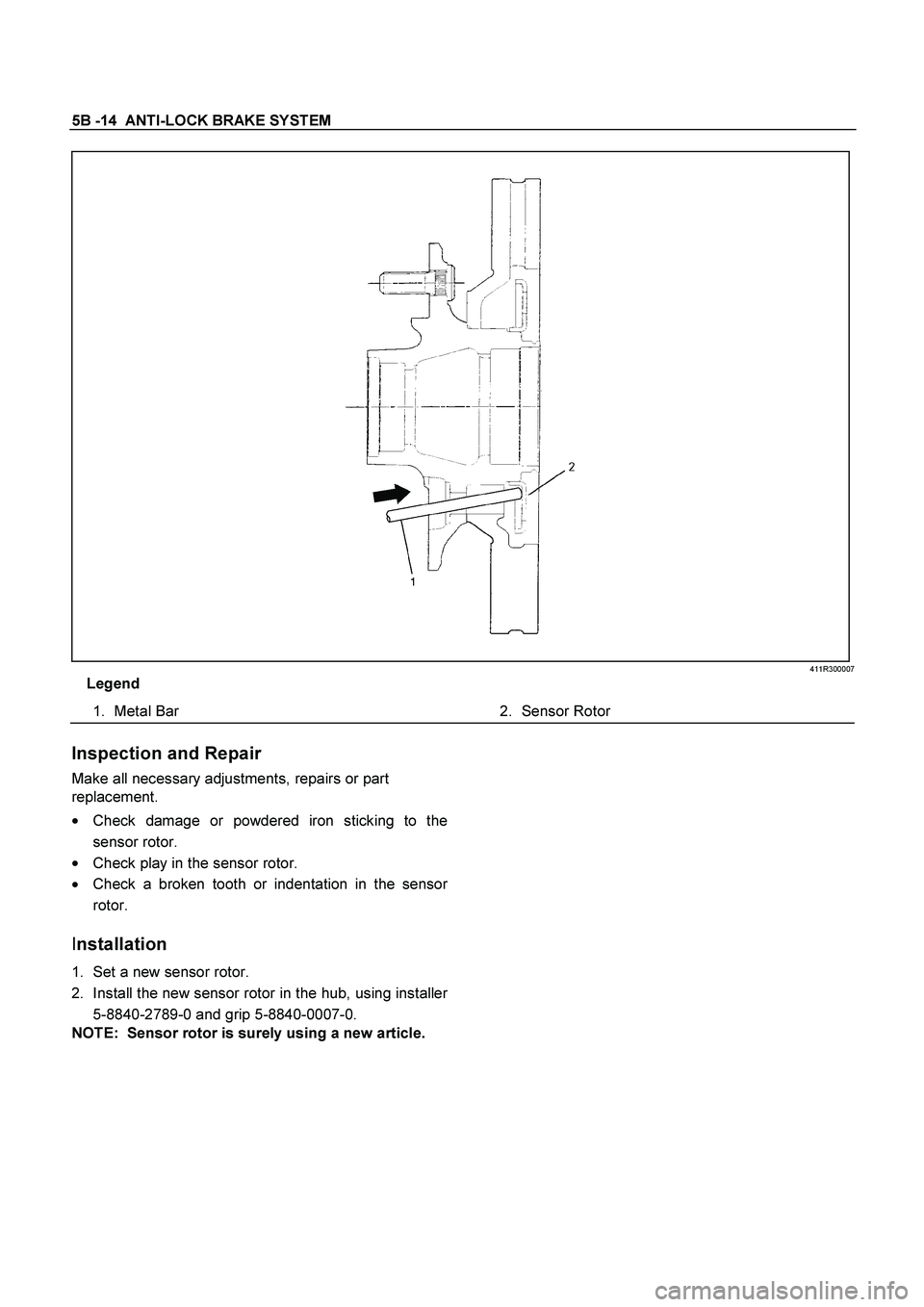
Legend
1.
Metal Bar
2.
Sensor Rotor
Inspection and Repair
Make all necessary adjustments, repairs or part
replacement.
�
Check damage or powdered iron sticking to the
sensor rotor.
�
Check play in the sensor rotor.
�
Check a broken tooth or indentation in the senso
r
rotor.
Installation
1. Set a new sensor rotor.
2. Install the new sensor rotor in the hub, using installe
r
5-8840-2789-0 and grip 5-8840-0007-0.
NOTE: Sensor rotor is surely using a new article.
Page 421 of 4264
ANTI-LOCK BRAKE SYSTEM 5B-15
411R300006
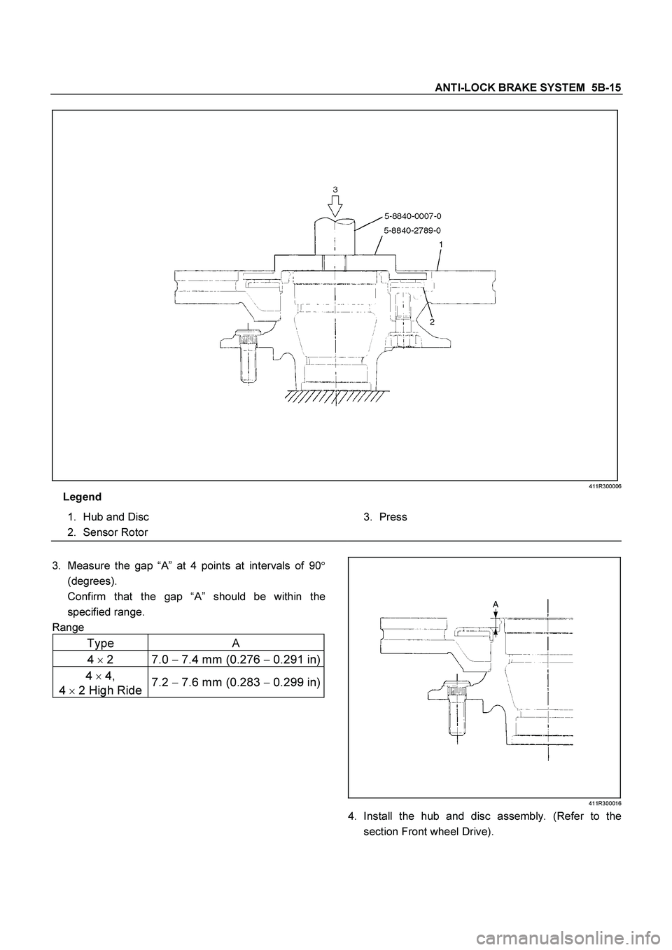
Legend
1.
Hub and Disc
2.
Sensor Rotor
3.
Press
3.
Measure the gap “A” at 4 points at intervals of 90�
(degrees).
Confirm that the gap “A” should be within the
specified range.
Range
Type A
4
�
2 7.0 �
7.4 mm (0.276 �
0.291 in)
4
�
4,
4
�
2 High Ride 7.2
� 7.6 mm (0.283
� 0.299 in)
411R300016
4. Install the hub and disc assembly. (Refer to the
section Front wheel Drive).
 Rear Right Wheel Speed Sensor Signal - Tooth
Chipping
LTW35AMF000101
Step Action
Value(s) Yes No
1 Was the “Basic Diagnostic Flow")
 Yes No
5 Repair or replace the rear left sensor rotor at rear
axle.
Was the action complete? - Verify repair
Go to Step 6 -
6 Select “Di")
 Rear Left Wheel Speed Sensor Signal - Tooth
Chipping
LTW35AMF000101
Step Action
Value(s) Yes No
1 Was the “Basic Diagnostic Flow C")
 ABS Operation Long Time
RTW45AMF000201
Step Action
Value(s) Yes No
1 Was the “Basic Diagnostic Flow Chart” performed?
- Go")