Page 482 of 4264
5C-56 BRAKES
REASSEMBLY
Reassembly Steps
1. Secondary piston
2. Primary piston
3. Cylinder body
4. Grommet
5. Reservoir tank
6. Stop pin
7. Bolt
8. Snap ring
9. Diaphragm
10. Cap
1. Secondary piston
Lubricate the piston cups on the secondary piston assemblies
with brake fluid.
Note :
Be sure to use a new piston.
2. Primary piston
Lubricate the piston cups on the primary piston assemblies
with brake fluid (1) and the rubber grease (2).
Note :
Be sure to use a new piston.
Page 485 of 4264
BRAKES 5C-59
330R300002
Important Operation-Removal
1. Brake pipe
When hurdling, be careful not to spill brake fluid over the
painted surfaces, as damage to the paint finish will result.
2. Master Cylinder Fixing Nut
3. Bracket (only RHD model)
4. Master Cylinder Assembly
NOTE:
When removing the master cylinder from the vacuum booster,
be sure to get rid of the internal negative pressure of the
vacuum booster (by, for instance, disconnecting the vacuum
hose) in advance.
If any negative pressure remains in the vacuum booster, the
piston may possibly come out when the master cylinder is
being removed, letting the brake fluid run out.
While removing the master cylinder, further, do not hold the
piston as it can be easily pulled out.
Page 622 of 4264
7C-20 CLUTCH
AIR BLEEDING
Bleed air from clutch operating cylinder according to the
following procedure.
Carefully monitor fluid level at master cylinder during bleeding
operation.
1. Set the paking brake.
2. Top up reservoir with recommended brake fluid.
3. Connect a transparent vinyl tube to air bleeder valve.
4. Fully depress clutch pedal several times.
5. With clutch pedal depressed, open bleeder valve to release
air.
6. Close bleeder valve.
7. Repeat steps 5 through 6 above until brake fluid flows from
air bleeder valve without air bubbles.
8. Bleed air from clutch damper according to the above
procedure.
9. Repeat the above bleeding procedure until the air
completely removed.
Page 637 of 4264
CLUTCH 7C-35
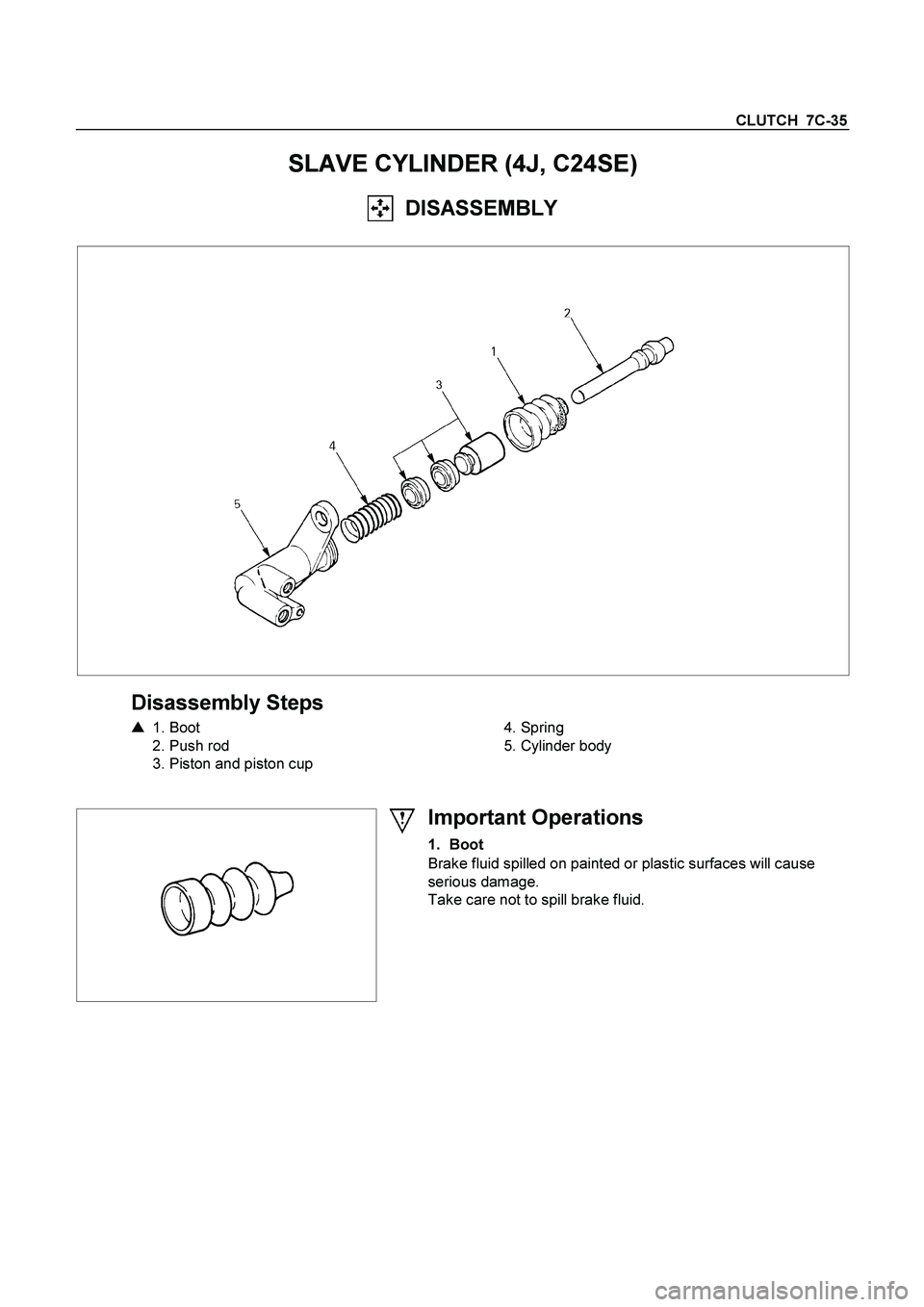
SLAVE CYLINDER (4J, C24SE)
DISASSEMBLY
Disassembly Steps
�
1. Boot
2. Push rod
3. Piston and piston cup
4. Spring
5. Cylinder body
Important Operations
1. Boot
Brake fluid spilled on painted or plastic surfaces will cause
serious damage.
Take care not to spill brake fluid.
Page 639 of 4264
CLUTCH 7C-37
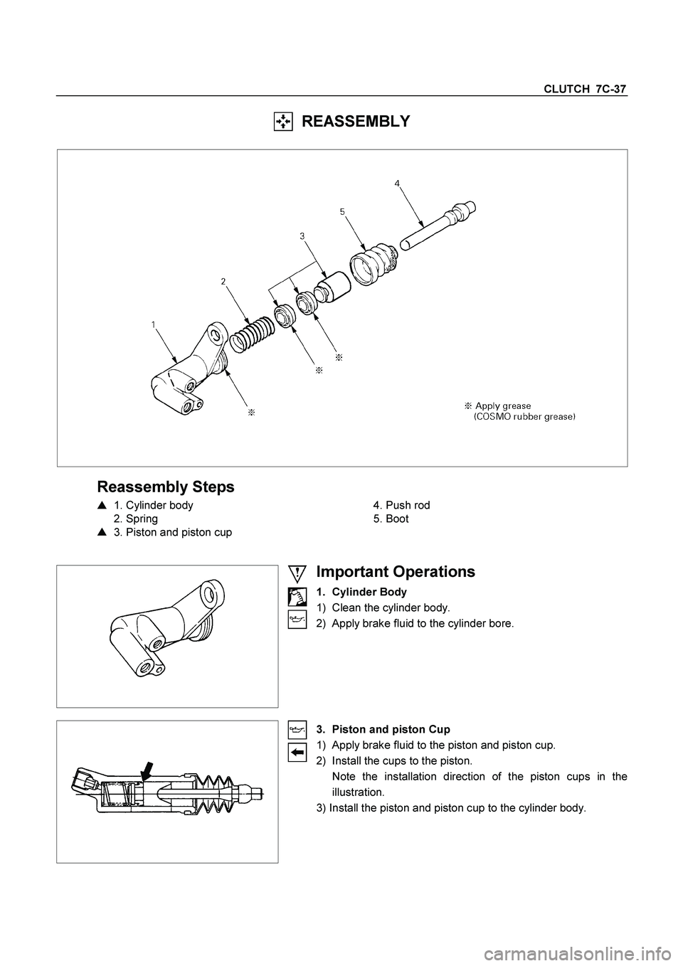
REASSEMBLY
Reassembly Steps
�
1. Cylinder body
2. Spring
�
3. Piston and piston cup
4. Push rod
5. Boot
Important Operations
1. Cylinder Body
1) Clean the cylinder body.
2) Apply brake fluid to the cylinder bore.
3. Piston and piston Cup
1) Apply brake fluid to the piston and piston cup.
2) Install the cups to the piston.
Note the installation direction of the piston cups in the
illustration.
3) Install the piston and piston cup to the cylinder body.
Page 919 of 4264

ELECTRICAL-BODY AND CHASSIS 8A-261
2. Even when the parking brake lever is pulled, the indicator light does not go off
Checkpoint Trouble Cause Countermeasure
Adjust the SW. installation
position or replace the parking
brake SW. Incorrect the parking brake
SW. adjustment or brake SW.
faulty
NG Thermo unit malfunction
Replace the brake fluid level
SW., or vacuum SW., or
repair a short circuit between
the parking brake SW.
connector 1
C-39
(Lever: 1
R-4) and 9 B-23
or the brake fluid level SW.
connector 2
C-37 and 9
B-23, (or the vacuum SW.
connector 1
C-38 and 9
B-23 : 4JH1-TC ONLY)
Check to see if the indicator
light goes off when the parking
brake SW. connector 1
C-39
(Lever: 1
R-4) is
di t d
Brake fluid level SW. or
vacuum SW. faulty or short
circuit
NG OK
Parking brake SW. installation
position and function
3. Oil pressure warning light does not go off while engine is running
Refer to ENGINE Section
Refer to ENGINE Section
NG Thermo unit malfunction
Repair a short circuit between
1
E-1 and 3 B-24
Check to see the warning light
goes off when the oil pressure
SW. connector
1
E-1 is disconnected
Short circuit
Replace the oil pressure unit
(or the oil pressure SW.)
Continuity between the oil
pressure SW. connector
1
E-1 and the body ground
when the engine is operating
Oil pressure unit (or oil
pressure SW) faulty
NG NG OK
OK
Engine oil pressure
Page 936 of 4264

8A-278 ELECTRICAL-BODY AND CHASSIS
Low Fuel Indicator Light Inspection
1. Disconnect the fuel tank unit wire connector.
2. Turn the key switch on. Check that the bulb lights.
If operation is not correct, remove and check the bulb or circuit.
or If check whether low fuel turns on fuel input (B-24) at the
time of open and key on.
� meter is check at low fuel
140R300006
Check level sensor operation
1. Remove the fuel tank unit.
2.
Apply battery voltage between terminal (B) and (C) through
a 1.12 watt bulb. Check that the bulb lights.
Note:
It will take a short time for the bulb light.
3. Submerge the sensor in fuel. Check that the bulb goes out.
If operation is not correct, replace the fuel tank unit.
BRAKE SYSTEM WARNING LIGHT
The brake system warning light comes on while the parking
brake is set and the engine run position.
Note:
The parking brake indicator light circuit is designed to
prevent driving of the vehicle with the parking brake on.
It does not indicate the condition of the parking brake
system.
The parking brake switch is in parallel with the brake fluid
switch.
The brake system warning light also comes on when reservoir
brake fluid level falls below the specified limit with the parking
brake released and the engine run position.
Page 1081 of 4264
ELECTRICAL-BODY AND CHASSIS 8A-423
No. Connector face No. Connector face
C-36
Silver
Engine room-LH ; Ground C-54
(6VE1)
(4JH1-TC)
OrangeABS sensor Front-LH
C-37
Black
Brake fluid level switch C-55
BrownThermo AMP
C-38
(4JH1-TC)
Vacuum switch C-56
(C24SE)
ECM
C-39
Parking brake switch (stick type) C-56
(4JA1-TC
4JH1-TC)
ECM-A
C-40
~
C-43 NOT USED C-57
(4JA1-TC
4JH1-TC)
ECM-B
C-44
White
Stop lamp switch C-58
~
C-62 NOT USED
C-45
~
C-49 NOT USED C-63
(6VE1)
(4JH1-TC)
Gray Front Fog lamp-RH
C-50
Condenser fan C-64
(6VE1)
(4JH1-TC)
Gray Front Fog lamp-LH
C-51
~
C-52 NOT USED C-65
~
C-66 NOT USED
C-53
(6VE1)
(4JH1-TC)
Orange ABS sensor Front-RH C-67
(6VE1)
(4JH1-TC)
BlackEHCU


(4JH1-TC)
OrangeABS sensor Front-LH
C-37
Black
Brake fluid leve")