Page 1357 of 4264
ENGINE ELECTRICAL 6D – 19
RTW46DSH000401
Important Operations
2. Rear rotor bearing
� Re-use improper parts.
5. Rectifier
6. Stator
Use a pair of long-nose plier to connect the stator coil
leads and the rectifier leads.
Finish the work as quickly as possible to prevent the
rectifier from heat transferred by the soldering.
RTW46DSH002101
3. Rotor Assembly
4. Pulley Assembly
Clamp the rotor in a vise and install the pulley nut.
Pulley Nut Torque N�m (kg�m/lb�ft)
83.3 � 98.0 (8.5 � 10.0 / 61 � 72)
RTW46DSH006001
Remove the tape from the splines.
RTW46DSH004901
The rear ball bearing is pressed into the wheel eccentric
groove. The bearing ring projects from the groove.
During installation, rotate the bearing to the point of
minimum bearing ring projection.
Inspect the rear cover bearing box and replace it if it is
damaged.
Page 1361 of 4264
ENGINE ELECTRICAL 6D – 23
DISASSEMBLY
RTW460LF000201
Disassembly Step
1.
Lead wire
14. Armature
2.
Bolt 15. Bolt
3.
Magnetic switch assembly 16. Bearing retainer
4.
Torsion spring 17. Pinion assembly
5.
Plunger 18. Pinion stopper clip
6.
Dust cover 19. Pinion stopper
7.
Magnetic switch 20. Return spring
8.
Screw 21. Pinion shaft
9.
Through bolt 22. Clutch
10.
Rear cover 23. Dust cover
11.
Motor assembly 24. Shift lever
12.
Brush holder 25. Gear case
13.
Yoke
Page 1362 of 4264
6D – 24 ENGINE ELECTRICAL
RTW46DSH002601
Important Operations
1. Lead Wire
Disconnect the lead wire at the magnetic switch.
RTW46DSH002701
3. Magnetic Switch Assembly
Remove the magnetic switch bolts, then remove the
switch from the shift lever.
RTW46DSH002801
Remove the torsion spring from the magnetic switch.
RTW46DSH002901
8. Through Bolt
9. Screw
10. Rear Cover
Remove the through bolts, then remove the rear cover.
RTW46DSH003001
11. Motor Assembly
Remove the four brushes from the brush holders.
Page 1365 of 4264

ENGINE ELECTRICAL 6D – 27
RTW46DSH003701
6. Use the circuit tester to check the armature for
continuity.
1 Hold the circuit tester probes against two
commutator segments.
2 Repear Step 1 at different segments of the
armature core.
There should be continuity between all segments of
the commutator.
If there is not, the armature must be replaced.
RTW46DSH003801
YOKE
1. Use a circuit tester to check the field winding ground.
1 Hold one circuit tester probe against the field
winding end or brush.
2 Hold the other circuit tester probe against the bare
surface of the yoke body.
There should be no continuity.
If there is continuity, the field coil is grounded.
The yoke must be replaced.
RTW46DSH003901
2. Use the circuit tester to check the field winding
continuity.
1 Hold one circuit tester probe against the “M”
terminal lead wire.
2 Hold the other circuit tester probe against the field
winding brush.
There should be continuity.
If there is no continuity, the yoke must be replaced.
Page 1367 of 4264
ENGINE ELECTRICAL 6D – 29
REASSEMBLY
RTW46DLF000601
Reassembly Steps
1.
Magnetic switch assembly
14. Pinion stopper
2.
Magnetic switch 15. Pinion stopper clip
3.
Dust cover 16. Bearing retainer
4.
Plunger 17. Bolt
5.
Torsion spring 18. Motor assembly
6.
Shift lever
19. Armature
7.
Gear case 20. Yoke
8.
Dust cover 21. Brush holder
9.
Bolt 22. Rear cover
10.
Pinion assembly 23. Screw
11.
Clutch 24. Through bolt
12.
Pinion shaft 25. Lead wire
13.
Rerurn spring
Page 1369 of 4264
ENGINE ELECTRICAL 6D – 31
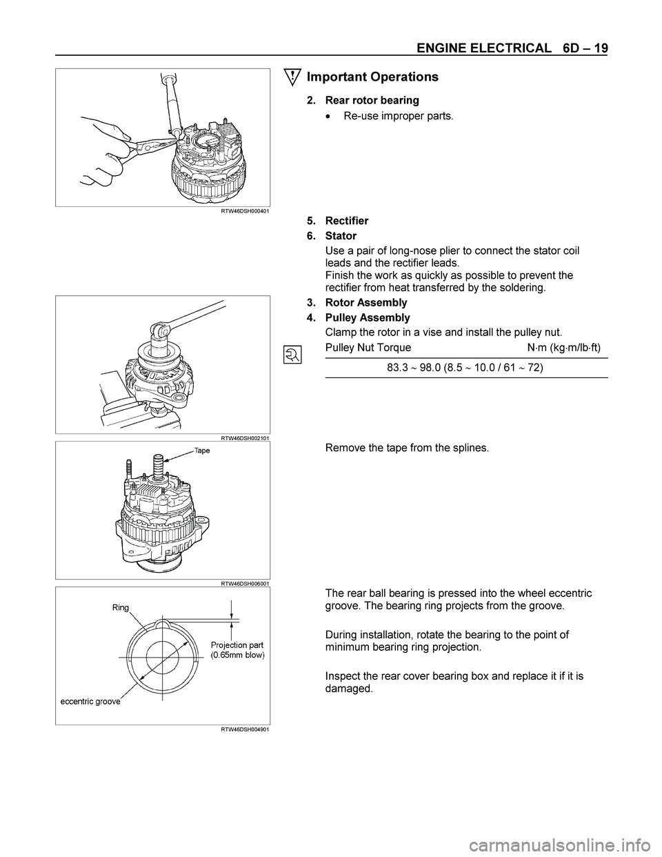
24. Through Bolt
Install the through bolts in the rear cover and tighten them
to the specified torque.
Through Bolt Torque N�m (kg�m/lb�ft)
8.1 (0.83/6.00)
065RY00044
RTW46DSH002601
25. Lead Wire
Connect the lead wire in the magnetic switch and tighten
the terminal nut to the specified torque.
Lead Wire Terminal Nut Torque N�m (kg�m/lb�ft)
8.6 (0.88/6.40)
RTW46DSH005801
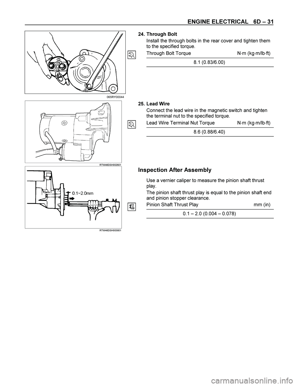
Inspection After Assembly
Use a vernier caliper to measure the pinion shaft thrust
play.
The pinion shaft thrust play is equal to the pinion shaft end
and pinion stopper clearance.
Pinion Shaft Thrust Play mm (in)
0.1 – 2.0 (0.004 – 0.078)
Page 1370 of 4264
6D – 32 ENGINE ELECTRICAL
MAGNETIC SWITCH
The following tests must be performed with the starter
motor fully assembled.
The yoke lead wire must be disconnected from the “M”
terminal.
To prevent coil burning, complete each test as quickly as
possible (within three to five seconds).
RTW46DSH004601
Temporarily connect the solenoid switch between the
clutch and the housing and run the following test.
Complete each test within three to five seconds.
1. Pull-in Test
Connect the battery negative terminal with the solenoid
switch body and the M terminal. When current is applied to
the S terminal from the battery positive terminal, the pinion
should flutter.
RTW46DSH005901
2. Hold-in Maintenance Test
Disconnect the lead at the M terminal. The pinion should
continue to flutter.
RTW46DSH004701
3. Return Test
Disconnect the battery positive lead at the S terminal.
The pinion should return to its home position.
Page 1436 of 4264

The engine control module (ECM) is located flower
panel just under the passenge")
6E–64 4JA1/4JH1 ENGINE DRIVEABILITY AND EMISSIONS
GENERAL DESCRIPTION FOR ECM AND
SENSORS
Engine Control Module (ECM)
The engine control module (ECM) is located flower
panel just under the passenger's seat.
The fuel quantity and injection timing related functions
are controlled by the pump control unit (PSG).
The engine control module (ECM) performs the
following functions.
Control of the ex haust gas re-circulation (EGR)
Control of the quick on start (QOS) glow control
system
Control of the A/C compressor
Ex ecution of the immobilizer function
Pump Control Unit (PSG) & Data Exchange
Between Control Module
The radial plunger distributor type injection pump uses
two control modules to ex ecute full control of the enginemanagement system.
Engine Control Module (ECM)
Pump Control Unit (PSG) = Pumpen Steuer Great
(German)
The pump control unit (PSG) receives signals from the
sensors inside the pump to determine the cam ring
rotation angle, the pump speed and the fuel
temperature .
These values are then compared to the desired values
sent by the engine control module (ECM) such as the
desired injection timing and the desired fuel injection
quantity.
The engine control module (ECM) processes all engine
data and data regarding the surrounding environment
received from ex ternal sensors to perform any engine
side adjustments.
Maps for both are encoded in both control units. The
control units input circuit process sensor data.
A Microprocessor then determines the operating
conditions and calculates set values for optimum
running.
The interchange of data between the engine control
module (ECM) and the pump control unit (PSG) is
perfumed via a CAN-bus system. The abbreviation CAN
stands for Controller Area Network. By having two
separate control modules, the high pressure solenoid
valve. This prevents the discharge of any disturbing
signals.
The information ex change between the two control
modules takes place via two means.
Via analogue signal leads
Via the CAN-bus
The analogue signal leads are used to ex change the
following information.
Engine speed signal (ECM terminal 91)
Pump Speed (ECM terminal 105)
Fuel Cutoff solenoid valve signal (MAB signal) (ECM
terminal 105)
The engine speed signal is sent from the ECM to PSG
based on the input from the crank shaft position (CKP)
sensor.
The analogue CKP sensor signal is converted by the
ECM into a square wave signal.
The fuel cutoff solenoid valve signal is also referred to
as MAB signal.
MAB in this case, refers to the German abbreviation
Magnet ventil ABschaltung that stands for high pressure
solenoid v alv e cut off.
The MAB signal wire is used for two purposes.
-As a reference for the engine control module (ECM) for
the pump speed (back up for the CKP sensor).
-To turn Off the engine.
Sel f Dia gn osis / Interfa ce / Si gn al
To High Pressure Solenoid
Engine Speed
Injection Timing
Accelerator Pedal
Injection Quantity
In ta ke Air Temperat ure
Response Signal
Ma ss Air Flow
Additional Signal
Others
Additional Operations To Timing Control Valve (TCV)
Engin e
Con trol
Modu le
(ECM) Cam Rin g Rota tiona l Angle
Fuel Temper atu re
High Pressure
Solenoid Valve
Pump
Con tr ol Fuel Inject ion
Unit (Mechanical)
(PSG)
Ti m i n
g Devi ce