2004 ISUZU TF SERIES air condition
[x] Cancel search: air conditionPage 2528 of 4264
6C-4 ENGINE FUEL (C24SE)
Fuel Metering
Engine Control Module (ECM) is in complete control of this fuel
delivery system during normal driving conditions.
The intake manifold function, like that of a diesel, is used only
to let air into the engine. The fuel is injected by separate
injectors that are mounted over the intake manifold.
The Manifold Absolute Pressure (MAP) sensor measures the
changes in the intake manifold pressure which result from
engine load and speed changes, which the MAP senso
r
converts to a voltage output.
This sensor generates the voltage to change corresponding to
the flow of the air drawn into the engine.
The changing voltage is transformed into an electric signal and
provided to the ECM.
With receipt of the signals sent from the MAP sensor, Intake
Air Temperature sensor and others, the ECM determines an
appropriate fuel injection pulse width feeding such information
to the fuel injector valves to effect an appropriate air/fuel ratio.
The Multiport Fuel Injection system utilizes an injection system
where the injectors turn on at every crankshaft revolution. The
ECM controls the injector on time so that the correct amount o
f
fuel is metered depending on driving conditions.
Two interchangeable "O" rings are used on the injector tha
t
must be replaced when the injectors are removed.
The fuel rail is attached to the top of the intake manifold and
supplies fuel to all the injectors.
Fuel is recirculated through the rail continually while the engine
is running. This removes air and vapors from the fuel as well
as keeping the fuel cool during hot weather operation.
The fuel pressure control valve that is mounted on the fuel rail
maintains a pressure differential across the injectors under all
operating conditions. It is accomplished by controlling the
amount of fuel that is recirculated back to the fuel tank based
on engine demand.
See Section "Driveability and Emission" for more information
and diagnosis.
Page 2547 of 4264
ENGINE ELECTRICAL 6D1-5
Battery fluid is a highly corrosive acid.
Should battery fluid come in contact with your eyes, skin,
fabric, or a painted surface, immediately and thoroughly rinse
the affected area with clean tap water.
Never allow metal tools or jumper cables to come in contact
with the positive battery terminal, or any other metal surface of
the vahicle. This will protect against a short circuit.
Always keep batteries out of reach of young children.
Jump Starting Procedure
1. Set the vehicle parking brake.
If the vahicle is equipped with an automatic transmission,
place the selector level in the "PARK" position.
If the vehicle is equipped with a manual transmission, place
the shift lever in the "NEUTRAL" position.
Turn "OFF" the ignition.
Turn "OFF" all lights and any other accessory requiring
electrical power.
2. Look at the built-in hydrometer.
If the indication area of the built-in hydrometer is completely
clear, do not try to jump start.
3.
Attach the end of one jumper cable to the positive terminal
of the booster battery.
Attach the other end of the same cable to the positive
terminal of the discharged battery.
Do not allow the vehicles to touch each other. This will
cause a ground connection, effectively neutralizing the
charging procedure.
Be sure that the booster battery has a 12 volt rating.
4.
Attach one end of the remaining cable to the negative
terminal of the booster battery.
Attach the other end of the same cable to a solid engine
ground (such as the air conditioning compressor bracket o
r
the generator mounting bracket) of the vehicle with the
discharged battery.
The ground connection must be at least 450 mm (18 in.)
from the battery of the vehicle whose battery is being
charged.
WARNING: NEVER ATTACH THE END OF THE JUMPER
CABLE DIRECTLY TO THE NEGATIVE TERMINAL OF THE
DEAD BATTERY.
5. Start the engine of the vehicle with the good battery.
Make sure that all unnecessary electrical accessories have
been turned "OFF".
6. Start the engine of the vehicle with the dead battery.
7. To remove the jumper cables, follow the above directions in
reverse order.
Be sure to first disconnect the negative cable from the
vehicle with the discharged battery.
Page 2556 of 4264
6D3-2 STARTING AND CHARGING SYSTEM
Starting System
General Description
Cranking Circuit
The cranking system consists of a battery, starter, starter
switch, starter relay, etc. These main components are
connected.
Starter
The cranking system employs a magnetic type reduction
starter in which the motor shaft is also used as a pinion shaft.
When the starter switch is turned on, the contacts of magnetic
switch are closed, and the armature rotates. At the same time,
the plunger is attracted, and the pinion is pushed forward by
the shift lever to mesh with the ring gear.
Then, the ring gear runs to start the engine. When the engine
starts and the starter switch is turned off, the plunger returns,
the pinion is disengaged from the ring gear, and the armature
stops rotation. When the engine speed is higher than the
pinion, the pinion idles, so that the armature is not driven.
Service Precaution
CAUTION:
Always use the correct fastener in the proper location.
When you replace a fastener, use ONLY the exact part
number for that application. ISUZU will call out those
fasteners that require a replacement after removal. ISUZU
will also call out the fasteners that require thread lockers
or thread sealant. UNLESS OTHERWISE SPECIFIED, do
not use supplemental coatings (Paints, greases, or other
corrosion inhibitors) on threaded fasteners or fastener
joint interfaces. Generally, such coatings adversely affect
the fastener torque and the joint clamping force, and may
damage the fastener. When you install fasteners, use the
correct tightening sequence and specifications. Following
these instructions can help you avoid damage to parts
and systems.
Diagnosis
Condition Possible cause Correction
Starter does not run Charging failure Repair charging system
Battery Failure Replace Battery
Terminal connection failure Repair or replace terminal connector
and/or wiring harness
Starter switch failure Repair or replace starter switch
Starter failure Repair or replace starter
Page 2562 of 4264
6D3-8 STARTING AND CHARGING SYSTEM
General On-Vehicle Inspection
The operating condition of charging system is indicated by the
charge warning lamp. The warning lamp comes on when the
starter switch is turned to "ON" position. The charging system
operates normally if the lamp goes off when the engine starts.
If the warning lamp shows abnormality or if undercharged or
overcharged battery condition is suspected, perform diagnosis
by checking the charging system as follows:
1. Check visually the belt and wiring connector.
2. With the engine stopped, turn the stator switch to "ON"
position and observe the warning lamp.
If lamp does not come on:
Disconnect wiring connector from generator, and ground
the terminal "L" on connector side.
If lamp comes on:
Repair or replace the generator.
Generator
Removal
1. Disconnect battery ground cable.
2. Move drive belt tensioner to loose side using wrench then
remove drive belt.
3. Disconnect terminal "B" wiring connector and connector.
4. Remove generator assembly.
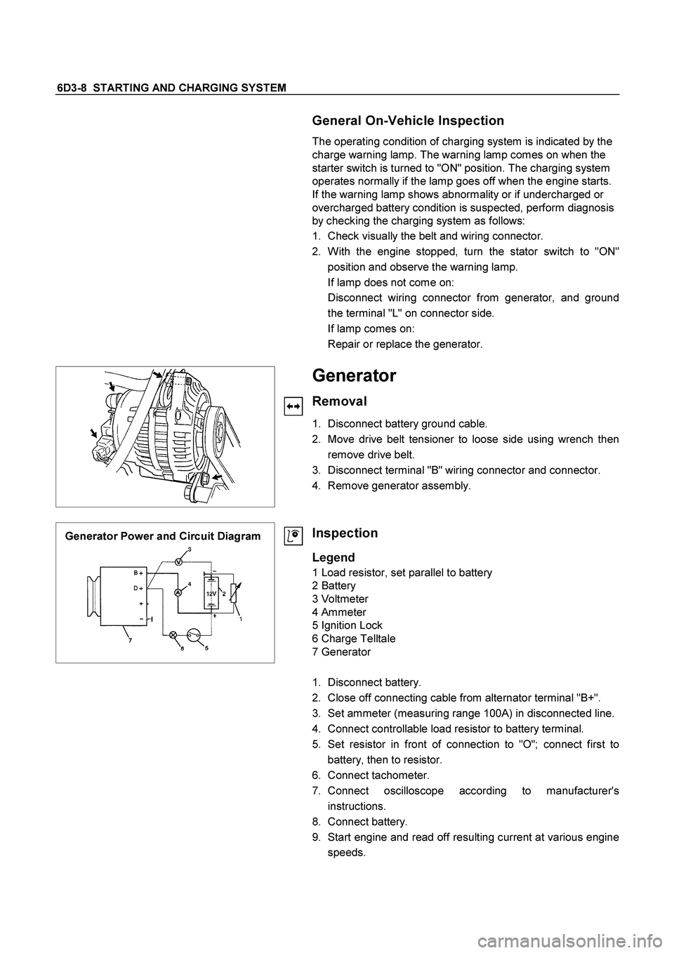
Generator Power and Circuit Diagram
Inspection
Legend
1 Load resistor, set parallel to battery
2 Battery
3 Voltmeter
4 Ammeter
5 Ignition Lock
6 Charge Telltale
7 Generator
1. Disconnect battery.
2. Close off connecting cable from alternator terminal "B+".
3. Set ammeter (measuring range 100A) in disconnected line.
4. Connect controllable load resistor to battery terminal.
5. Set resistor in front of connection to "O"; connect first to
battery, then to resistor.
6. Connect tachometer.
7. Connect oscilloscope according to manufacturer's
instructions.
8. Connect battery.
9. Start engine and read off resulting current at various engine
speeds.
Page 2566 of 4264
6D3-12 STARTING AND CHARGING SYSTEM
Diagnosis
The EP regulator incorporates diagnostics which will illuminate
the warning lamp as a result of fault conditions in the generator
and external circuitry.
These conditions include:
1.
An open circuit in the regulator battery sensing wire (S
Terninal)
2. An open circuit or excessive voltage drop in the B+ cable.
3. An open circuit in the generator phase connection.
4. Overcharging of the battery.
5. Regulator output stage short circuit.
6. Open circuit rotor.
The regulator compares the voltage at B+ with the voltage at
the "S" terminal connceted to battery positive. If the voltage
differential exceeds a predetermined threshold, the regulator
will operate in backup mode to limit the output voltage to a safe
level. The warning lamp; will remain illuminated as along as
these conditions prevail.
Sources of high resistance which will trigger the warning lamp
are:
a. Poor contact in wiring harness connectors.
b. Poor contact between rectifier and regulator.
c. High resistance in fusible link assembly.
Caution:
When bench testing the generator it is important that the
warning lamp wattage of 2 watts is not exceeded.
Reversal of the "S" and "L" on the regulator will damage
the regulator.
The correct plug for the regulator is a 9 122 067 011 for the
Bosch tye and for the Shinagawa connector the number is
X02FW.
See appendix 1 for daignostic matrix.
Before testing or disassembling the generator please observe
the following points.
1. When testing the diodes with AC type testers the RMS.
Vlotage output must not exceed 12.0 volts, it is
recommended that the stator should be disconnected
during this test.
2. Where zener power diodes are used, the breakdown
voltage should be tested to ensure all diodes have the
same zener voltage.
3. Insulation tests on the rotor and stator should use a voltage
not exceeding 110v for a series test lamp. The rectifie
r
must be disconnected from the stator prior to testing.
4. When carrying out repairs to the charging system always
disconnected the battery negative first, and reconnect i
t
last.
Page 2582 of 4264
6E–6 ENGINE DRIVEABILITY AND EMISSIONS
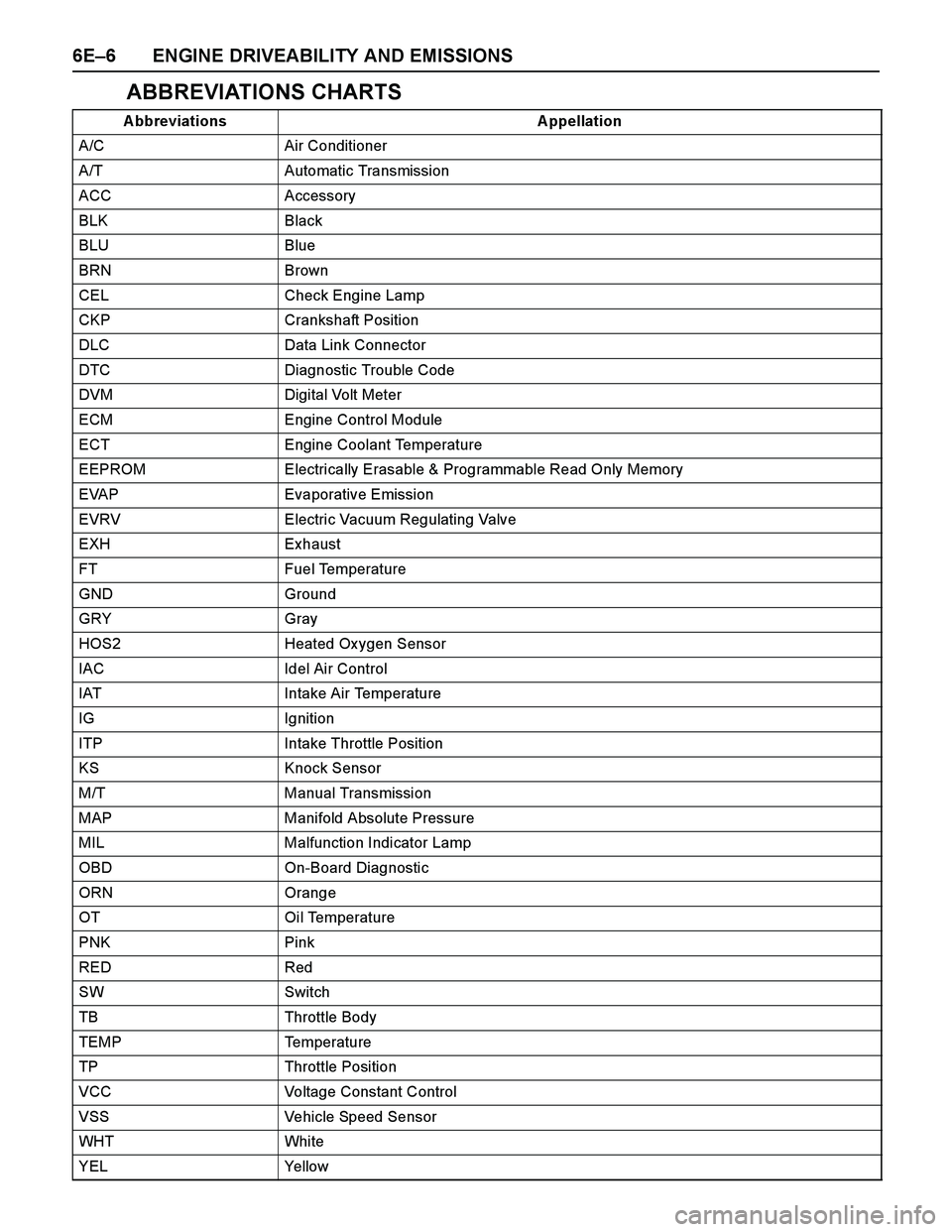
ABBREVIATIONS CHARTS
A bbreviations A ppellation
A/C Air Conditioner
A/T Automatic Transmission
ACC Accessory
BLK Black
BLU Blue
BRN Brown
CEL Check Engine Lamp
CKP Crankshaft Position
DLC Data Link Connector
DTC Diagnostic Trouble Code
DVM Digital Volt Meter
ECM Engine Control Module
ECT Engine Coolant Temperature
EEPROM Electrically Erasable & Programmable Read Only Memory
EVAP Evaporative Emission
EVRV Electric Vacuum Regulating Valve
EXH Exhaust
FT Fuel Temperature
GND Ground
GRY Gray
HOS2 Heated Ox ygen Sensor
IAC Idel Air Control
IAT Intake Air Temperature
IG Ignition
ITP Intake Throttle Position
KS Knock Sensor
M/T Manual Transmission
MAP Manifold Absolute Pressure
MIL Malfunction Indicator Lamp
OBD On-Board Diagnostic
ORN Orange
OT Oil Temperature
PNK Pink
RED Red
SW Switch
TB Throttle Body
TEMP Temperature
TP Throttle Posi tion
VCC Voltage Constant Control
VSS Vehicle Speed Sensor
WHT Whi te
Y EL Yellow
Page 2624 of 4264
6E–48 ENGINE DRIVEABILITY AND EMISSIONS
GENERAL DESCRIPTION FOR ECM AND
SENSORS
Engine Control Module (ECM)
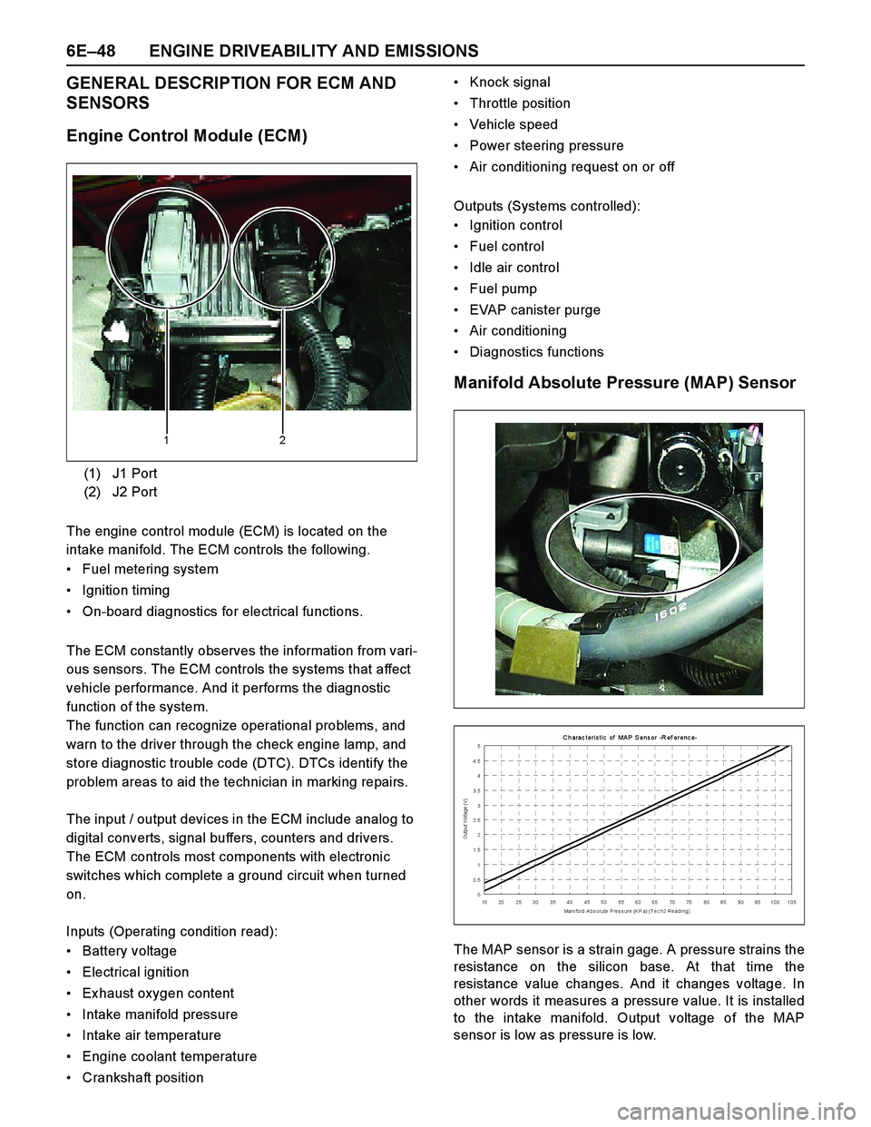
The engine control module (ECM) is located on the
intake manifold. The ECM controls the following.
Fuel metering system
Ignition timing
On-board diagnostics for electrical functions.
The ECM constantly observes the information from vari-
ous sensors. The ECM controls the systems that affect
vehicle performance. And it performs the diagnostic
function of the system.
The function can recognize operational problems, and
warn to the driver through the check engine lamp, and
store diagnostic trouble code (DTC). DTCs identify the
problem areas to aid the technician in marking repairs.
The input / output devices in the ECM include analog to
digital converts, signal buffers, counters and drivers.
The ECM controls most components with electronic
switches which complete a ground circuit when turned
on.
Inputs (Operating condition read):
Battery voltage
Electrical ignition
Ex haust oxygen content
Intake manifold pressure
Intake air temperature
Engine coolant temperature
Crankshaft positionKnock signal
Throttle position
Vehicle speed
Power steering pressure
Air conditioning request on or off
Outputs (Systems controlled):
Ignition control
Fuel control
Idle air control
Fuel pump
EVAP canister purge
Air conditioning
Diagnostics functions
Manifold Absolute Pressure (MAP) Sensor
The MAP sensor is a strain gage. A pressure strains the
resistance on the silicon base. At that time the
resistance value changes. And it changes voltage. In
other words it measures a pressure value. It is installed
to the intake manifold. Output voltage of the MAP
sensor is low as pressure is low. (1) J1 Port
(2) J2 Port
12
C h arac teris tic of MA P S ens or -R ef erenc e-
0 0.51 1.52 2.53 3.54 4.55
15 20 25 30 35 40 45 50 55 60 65 70 75 80 85 90 95 100 105
Mani fold A bs olute P res s ure (K P a) (T ec h2 Reading)
Output Voltage (V)
Page 2625 of 4264
ENGINE DRIVEABILITY AND EMISSIONS 6E–49
Throttle Position Sensor (TPS)
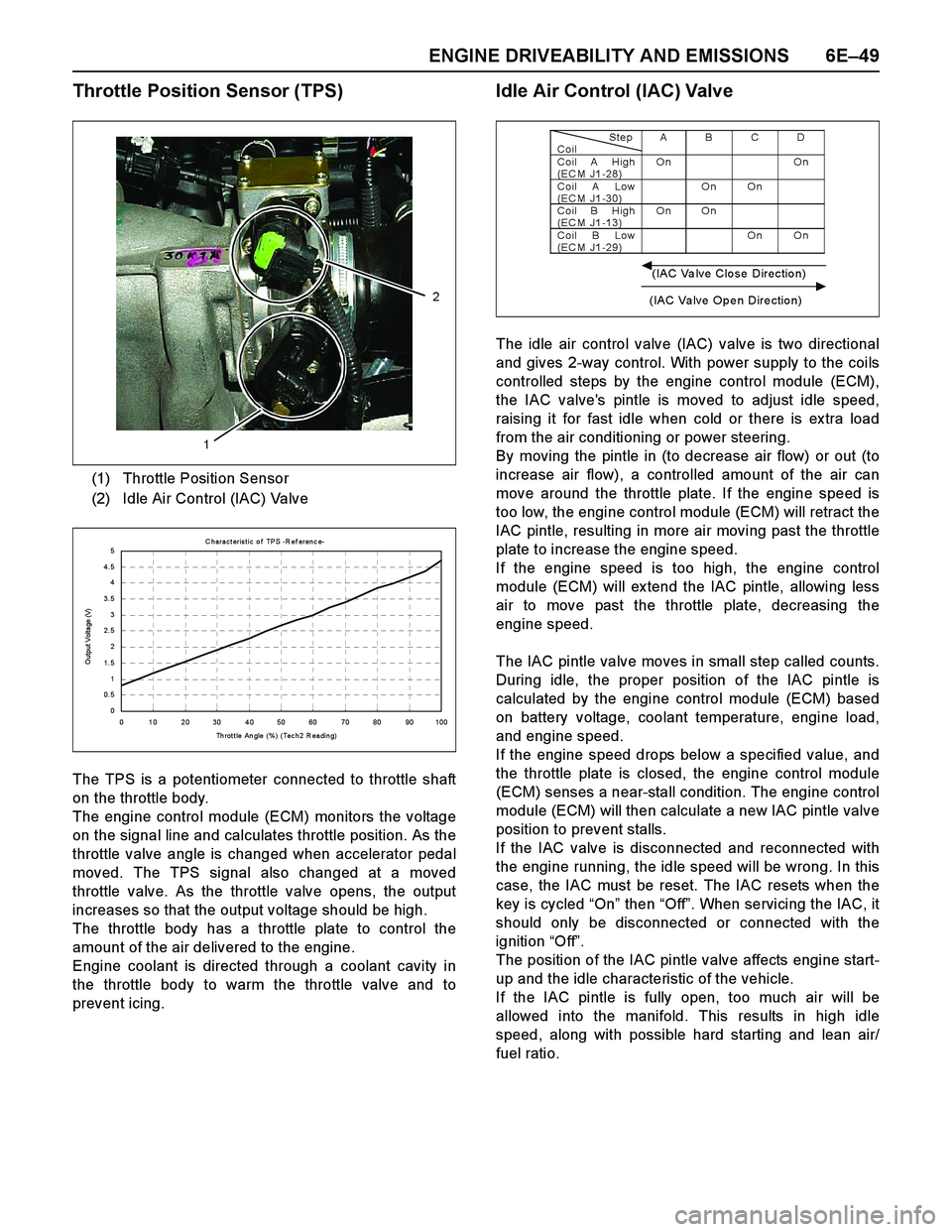
The TPS is a potentiometer connected to throttle shaft
on the throttle body.
The engine control module (ECM) monitors the voltage
on the signal line and calculates throttle position. As the
throttle valve angle is changed when accelerator pedal
moved. The TPS signal also changed at a moved
throttle valve. As the throttle valve opens, the output
increases so that the output voltage should be high.
The throttle body has a throttle plate to control the
amount of the air delivered to the engine.
Engine coolant is directed through a coolant cavity in
the throttle body to warm the throttle valve and to
prevent icing.
Idle Air Control (IAC) Valve
The idle air control valve (IAC) valve is two directional
and gives 2-way control. With power supply to the coils
controlled steps by the engine control module (ECM),
the IAC valve's pintle is moved to adjust idle speed,
raising it for fast idle when cold or there is ex tra load
from the air conditioning or power steering.
By moving the pintle in (to decrease air flow) or out (to
increase air flow), a controlled amount of the air can
move around the throttle plate. If the engine speed is
too low, the engine control module (ECM) will retract the
IAC pintle, resulting in more air moving past the throttle
plate to increase the engine speed.
If the engine speed is too high, the engine control
module (ECM) will ex tend the IAC pintle, allowing less
air to move past the throttle plate, decreasing the
engine speed.
The IAC pintle valve moves in small step called counts.
During idle, the proper position of the IAC pintle is
calculated by the engine control module (ECM) based
on battery voltage, coolant temperature, engine load,
and engine speed.
If the engine speed drops below a specified value, and
the throttle plate is closed, the engine control module
(ECM) senses a near-stall condition. The engine control
module (ECM) will then calculate a new IAC pintle valve
position to prevent stalls.
If the IAC valve is disconnected and reconnected with
the engine running, the idle speed will be wrong. In this
case, the IAC must be reset. The IAC resets when the
key is cycled “On” then “Off”. When servicing the IAC, it
should only be disconnected or connected with the
ignition “Off”.
The position of the IAC pintle valve affects engine start-
up and the idle characteristic of the vehicle.
If the IAC pintle is fully open, too much air will be
allowed into the manifold. This results in high idle
speed, along with possible hard starting and lean air/
fuel ratio. (1) Throttle Position Sensor
(2) Idle Air Control (IAC) Valve
1
2
C haract erist ic of TPS -R ef erenc e-
0 0. 51 1. 52 2. 53 3. 54 4. 55
0 102030405060708090100
Th rot t le An gle ( % ) ( Tec h 2 R ea di n g)
Output Voltage (V)
StepCoilAB CDCoil A High
(EC M J1-28)On On
Coil A Low
(EC M J1-30)On On
Coil B High
(EC M J1-13)On On
Coil B Low
(EC M J1-29)On On
(IAC Valve Close Direction)
(IAC Valve Open Direction)