Page 2422 of 4264

PAGE
Camshaft Housing, Check for Plance Surface ......................................................... 6A-39
Cylinder Head, Removal and Installation .............")
6A-2 ENGINE MECHANICAL (C24SE)
PAGE
Camshaft Housing, Check for Plance Surface ......................................................... 6A-39
Cylinder Head, Removal and Installation .................................................................. 6A-39
Cylinder Head, Disassemble and Assemble ............................................................. 6A-42
Valve, Grind ................................................................................................................. 6A-44
Valve Guide, Ream ..................................................................................................... 6A-44
Valve Seating, Mill ....................................................................................................... 6A-45
Cylinder Head, Overhaul............................................................................................. 6A-45
Flywheel ....................................................................................................................... 6A-46
Starter Ring Gear(Manual Transmission) ................................................................. 6A-47
Seal Ring, Crankshaft ................................................................................................. 6A-48
Seal Ring, Crankshaft Rear ........................................................................................ 6A-48
Oil Pan and Bearing Bridge........................................................................................ 6A-49
OPERATIONS ON CRANK DRIVE ................................................................................... 6A-51
Con-Rod Bearing......................................................................................................... 6A-51
Piston with Con-Rod ................................................................................................... 6A-51
Con-Rod ....................................................................................................................... 6A-52
Pistion Rings ............................................................................................................... 6A-53
OPERATIONS ON REMOVED ENGINE ........................................................................... 6A-55
Crankshaft ................................................................................................................... 6A-55
Bearing Free Play Measurement ................................................................................ 6A-57
Plastigage Method ...................................................................................................... 6A-57
Micrometer and gauge method .................................................................................. 6A-58
Bypass Valve ............................................................................................................... 6A-59
Oil Filter ....................................................................................................................... 6A-59
Oil Pump ...................................................................................................................... 6A-59
Oil Pump Safety Valve ................................................................................................ 6A-60
Oil Pump(Overhaul) .................................................................................................... 6A-60
OPERATIONS ON OIL CIRCULATION ............................................................................ 6A-61
Cylinder Head Safety Valve ........................................................................................ 6A-61
OPERATIONS ON COOLING SYSYTEM ......................................................................... 6A-63
Cooling System, Check for Leakes ........................................................................... 6A-63
Cooling System, Fill Up and Bleed ............................................................................ 6A-63
Refill Coolant ............................................................................................................... 6A-64
Ignition Timing, Check................................................................................................ 6A-64
Page 2466 of 4264
6A-46 ENGINE MECHANICAL (C24SE)
Inspection
Check contact pattern (I
) on valve seat and in cylinder head.
Clean
Valves, valve guides, cylinder head.
Flywheel
Removal
1. Remove transmission and clutch.
2. Remove flywheel while locking with 5-88400-446-0.
Torque - Angle Method
Flywheel to crankshaft - 65 Nm/6.5 kgf�
m.+30�
to 45�
Important!
Use new bolts.
Do not apply grease to the thread.
Installation
1. Install clutch and transmission.
Component Parts
Flywheel and Ring gear. (Manual Transmission)
Page 2467 of 4264
ENGINE MECHANICAL (C24SE) 6A-47
Starter Ring Gear (Manual Transmission)
Removal
1. Remove flywheel according to the corresponding
operation.
2. Drill starter ring gear underneath tooth gap approx.
8mm/0.30in. deep with 8mm/0.25in. diameter drill.
3. Separate starter ring gear with chisel on the drilling point.
Installation
1. Install starter ring gear with inner chamfered edge to
flywheel.
2. Heat starter ring gear evenly to 180�
C /356�
F to 230�
C
/446�
F (yellow paint mark)
3. Install flywheel according to the corresponding operation.
Inspection
Lateral run-out of starter ring gear - max. 0.5mm/0.02in.
Page 2468 of 4264

Seal Ring, Crankshaft
(Oil Pump Housing)
Removal
1. Remove toothed belt rear cover according to the
corresponding operation.
2. Remove sealing ring by")
6A-48 ENGINE MECHANICAL (C24SE)
Seal Ring, Crankshaft
(Oil Pump Housing)
Removal
1. Remove toothed belt rear cover according to the
corresponding operation.
2. Remove sealing ring by making hole in middle of ring,
turning in self-tapping screw and edging out.
Installation
1 Install the protective sleeve to the crankshaft.
2. Coat the sealing lip with protective grease.
3. Install the sealing ring.
4. Install the sealing ring using 5-8840-0455-0.
5. Install the rear toothed belt cover and toothed belt
according to the corresponding operations.
6. Replace the sealing ring with a new one.
7. Tighten the belt to the crankshaft.
Seal Ring, Crankshaft Rear
Removal
1. Remove transmission and clutch.
2. Remove flywheel or flex plate according to the
corresponding operations.
3. Make hole in middle of sealing ring, turn in self-tapping
screw and edge out.
Installation
1. Install protective sleeve.
2. Coat sealing lip with Protective Grease.
3. Install sealing ring using 5-8840-0459-0 and 5-8840-
2597-0.
4. Install flywheel, clutch and transmission.
Page 2469 of 4264
ENGINE MECHANICAL (C24SE) 6A-49
Reassembly
Reassemble clutch assembly.
Disassembly
Disassemble clutch assembly to flywheel using 5-8840-2634-0
Torque Angle-Method
Clutch assembly to flywheel-17.6Nm/1.8 kgf �
m.
RTW46ASH002801
Oil Pan and Bearing Bridge
Removal
1. Remove the crossmember.
2. Shift downward the power steering unit (and front axle [4 �4 model only]).
3. Loosen fixing bolts.
4. Remove oil pan from oil pump and cylinder block.
5. Remove oil intake pipe, oil intake pipe bracket, and oil baffle plate.
6. Remove the bearing bridge.
Page 2475 of 4264
 6A-55
OPERATIONS ON REMOVED ENGINE
Crankshaft
Removal
1. Mount the engine on an engine overhaul stand with
appropriate ad")
ENGINE MECHANICAL (C24SE) 6A-55
OPERATIONS ON REMOVED ENGINE
Crankshaft
Removal
1. Mount the engine on an engine overhaul stand with
appropriate adapters.
2. Remove the aggregates, flywheel/drive disc, oil pan,
bearing bridge and oil pump according to the
corresponding operation.
3. Mark the con-rod bearing cover.
4. Remove the crankshaft bearing cover.
5. Remove the crankshaft from cylinder block.
Inspection
Remove and install all parts if necessary.
Crankshaft pulse pickup sensor rotor inspection and repair.
Inspect the crankshaft pulse pickup sensor rotor for excessive
wear and damage.
Replace the crankshaft pulse pickup rotor if the inspection
results exceed wear and damage limits.
Installation
1. Install the crankshaft pulse pickup sensor.
Torque: 13N�
�� �m (1.3 kgf�
�� �m)
2. Install new bearing shells into the cylinder block and
bearing cover.
3. Coat the bearing shafts with engine oil.
For oversizes-see “Technical Data”
4. Install a new crankshaft into the cylinder block.
Note
The sealing of the crankshaft can be corrected with light
blows with a rubber hammer on the crank arm (arrowed).
Page 2476 of 4264

5. Apply a bead of sealant (TB-1207C or equivalent) in the
grooves of both bearing shells.
Important!
After installation of bearing cover, press in")
6A-56 ENGINE MECHANICAL (C24SE)
5. Apply a bead of sealant (TB-1207C or equivalent) in the
grooves of both bearing shells.
Important!
After installation of bearing cover, press in sealing compound
again from above, until compound emerges at the joints.
Torque - Angle Method
Bearing cover to cylinder block - 50 N�m (5.1 kgf�m) +40� to
50�
Con-rod bearing cover to con-rod - 35 N�
m (3.5 kgf�
m) +45�
to
60�
.
Use new bolts.
6. Install oil pump, oil pan, bearing bridge rear crankshaft
sealing, flywheel/drive plate, and aggregates according to
the corresponding operations.
Inspection
Bearing play - bearing cover removed
Measure
With "Plastigage" (ductile plastic threads)
Cut threads to length of bearing width and lay axiaity between
crankshaft journal and bearing shell (arrowed).
Install bearing cover with correct torque.
Important!
Grease crankshaft journal and lubricate bearing shell slightly
so that the thread does not tear when the bearing cover is
moved.
Crankshaft
Inspection
End play when bearing shells are installed.
Front end contact surfaces of flywheel/flexible plate.
Permissible end play - see "Technical Data "
Page 2506 of 4264
6A-86 ENGINE MECHANICAL (C24SE)
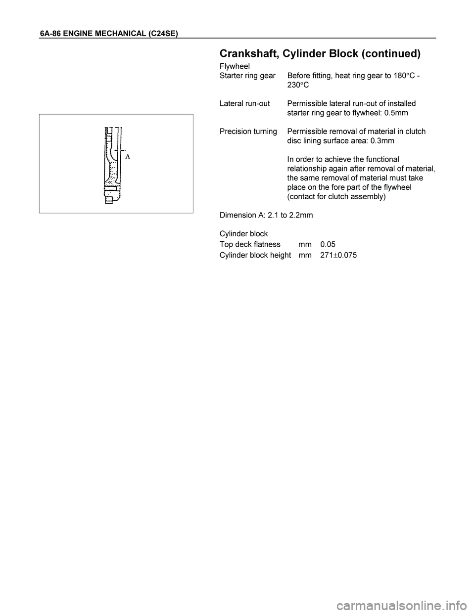
Crankshaft, Cylinder Block (continued)
Flywheel
Starter ring gear Before fitting, heat ring gear to 180�C -
230�C
Lateral run-out Permissible lateral run-out of installed
starter ring gear to flywheel: 0.5mm
Precision turning Permissible removal of material in clutch
disc lining surface area: 0.3mm
In order to achieve the functional
relationship again after removal of material,
the same removal of material must take
place on the fore part of the flywheel
(contact for clutch assembly)
Dimension A: 2.1 to 2.2mm
Cylinder block
Top deck flatness mm 0.05
Cylinder block height mm 271�0.075

Inspection
Check contact pattern (I
) on valve seat and in cylinder head.
Clean
Valves, valve guides, cylinder head.
Flywheel
Removal
1. Rem")
 6A-47
Starter Ring Gear (Manual Transmission)
Removal
1. Remove flywheel according to the corresponding
operation.
2. Drill starter ring gear underneath tooth g")
 6A-49
Reassembly
Reassemble clutch assembly.
Disassembly
Disassemble clutch assembly to flywheel using 5-8840-2634-0
Torque Angle-Method
Clutch assemb")