Page 1589 of 4264

4JA1/4JH1 ENGINE DRIVEABILITY AND EMISSIONS 6E–217
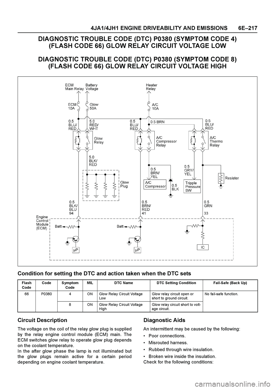
DIAGNOSTIC TROUBLE CODE (DTC) P0380 (SYMPTOM CODE 4)
(FLASH CODE 66) GLOW RELAY CIRCUIT VOLTAGE LOW
DIAGNOSTIC TROUBLE CODE (DTC) P0380 (SYMPTOM CODE 8)
(FLASH CODE 66) GLOW RELAY CIRCUIT VOLTAGE HIGH
Condition for setting the DTC and action taken when the DTC sets
Circuit Description
The voltage on the coil of the relay glow plug is supplied
by the relay engine control module (ECM) main. The
ECM switches glow relay to operate glow plug depends
on the coolant temperature.
In the after glow phase the lamp is not illuminated but
the glow plugs remain active for a certain period
depending on engine coolant temperature.
Diagnostic Aids
An intermittent may be caused by the following:
Poor connections.
Misrouted harness.
Rubbed through wire insulation.
Broken wire inside the insulation.
Check for the following conditions:
Flash
CodeCode Symptom
CodeMIL DTC Name DTC Setting Condition Fail-Safe (Back Up)
66 P0380 4 ON Glo w Re la y Circuit Volta ge
Lo wGlow relay circuit open or
sho rt to ground circuit.No fa il-sa fe fun ctio n.
8 ON Glo w Re la y Circuit Volta ge
HighGlo w re la y circuit short to vo lt-
age circuit.
Page 1632 of 4264
6E–260 4JA1/4JH1 ENGINE DRIVEABILITY AND EMISSIONS
DIAGNOSTIC TROUBLE CODE (DTC) P0561 (SYMPTOM CODE A)
(FLASH CODE 18) IGNITION SWITCH CIRCUIT MALFUNCTION
DIAGNOSTIC TROUBLE CODE (DTC) P0561 (SYMPTOM CODE B)
(FLASH CODE 18) IGNITION SWITCH CIRCUIT MALFUNCTION
Condition for setting the DTC and action taken when the DTC sets
Flash
CodeCode Symptom
CodeMIL DTC Name DTC Setting Condition Fail-Safe (Back Up)
18 P0561 A OFF Ignitio n Switch Circuit Ma l-
functionThe ECM recognized ignition
switch turn o ff signa l during
ECM is activated.ECM stops engine.
B OFF Ignitio n Switch Circuit Ma l-
function Ignitio n switch circuit is mal-
function.
Page 1633 of 4264

4JA1/4JH1 ENGINE DRIVEABILITY AND EMISSIONS 6E–261
Circuit Description
The ECM monitors the ignition switch signal on the feed
terminal to the ECM. If the ignition switch signal with
malfunction, DTC P0561 (Symptom Code A) or DTC
P0561 (Symptom Code B) will be stored.
Diagnostic Aids
An intermittent may be caused by the following:
Poor connections.
Misrouted harness.Rubbed through wire insulation.
Broken wire inside the insulation.
Check for the following conditions:
Poor connection at ECM-Inspect harness connectors
for backed out terminals, improper mating, broken
locks, improperly formed or damaged terminals, and
poor terminal to wire connection.
Damaged harness-Inspect the wiring harness for
damage. If the harness appears to be OK, observe
the “Ignition Status” display on the Tech2 while
moving connectors and wiring harness related to the
sensor.
Diagnostic Trouble Code (DTC) P0561 (Symptom Code A) (Flash Code 18)
Ignition Switch Circuit Malfunction
Diagnostic Trouble Code (DTC) P0561 (Symptom Code B) (Flash Code 18)
Ignition Switch Circuit Malfunction
Step Action Value(s) Yes No
1Was the “On-Board Diagnostic (OBD) System Check”
performed?
—Go to Step 2Go to On Board
Diagnostic
(OBD) System
Check
2 1. Connect the Tech 2.
2. Review and record the failure information.
3. Select “F0: Read DTC Infor As Stored By ECU” in
“F0: Diagnostic Trouble Codes”.
Is the DTC P0561 (Symptom Code A) or P0561
(Symptom Code B) stored as “Present Failure”?—Go to Step 3Refer to
Diagnostic Aids
and Go to Step
3
3 1. Using the Tech 2, ignition “On” and engine “Off”.
2. Select “F1: Clear DTC Information” in “F0:
Diagnostic Trouble Codes” with the Tech 2 and
clear the DTC information.
3. Operate the vehicle and monitor the “F0: Read
DTC Infor As Stored By ECU” in the “F0:
Diagnostic Trouble Codes”.
Was the DTC P0561 (Symptom Code A) or P0561
(Symptom Code B)stored in this ignition cycle?—Go to Step 4Refer to
Diagnostic Aids
and Go to Step
4
4 Check the “Engine fuse (10A)”.
If the fuse is burnt out, repair as necessary.
Was the problem found?—Verify repair Go to Step 5
Page 1634 of 4264
6E –262 4JA1/4JH1 ENGINE DRIVEABILITY AND EMISSIONS
5 Using the DVM and check the ignition power feed
circuit.
Breaker box is available:
1. Ignition “Off ”, engine “Off ”.
2. Install the breaker box as type A. (ECM disconnected)
3. Check the circuit for open or short to ground circuit.
Was the problem found?
Breaker box is not available: 1. Ignition “Off ”, engine “Off ”.
2. Disconnect the ECM connector.
3. Check the circuit for open or short to ground circuit.
Was the problem found?
— Repair faulty
harness and verify repair Go to Step 6
6 Check the ignition switch. If a poor/faulty connection is found, repair as
necessary.
Was the problem found? —Verify repair Go to Step 7
7 Is the ECM programmed with the latest software release?
If not, download the latest software to the ECM using
the “ SPS (Service Programming System) ”.
Was the problem solved? —Verify repair Go to Step 8
Step Action Value(s) Yes No
39
Breaker Box
��
C-107
�
39
9
C-56
C-107
Page 1640 of 4264

6E–268 4JA1/4JH1 ENGINE DRIVEABILITY AND EMISSIONS
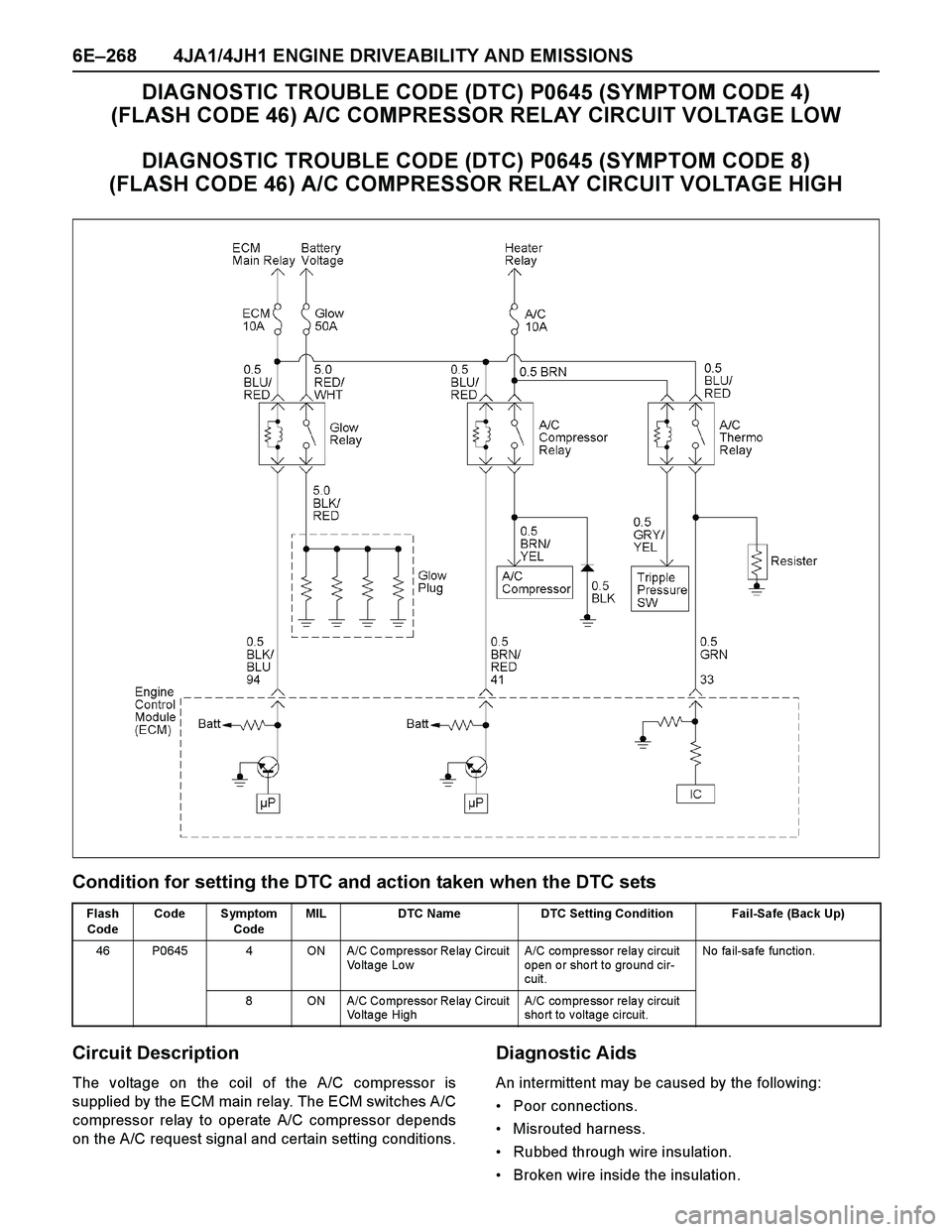
DIAGNOSTIC TROUBLE CODE (DTC) P0645 (SYMPTOM CODE 4)
(FLASH CODE 46) A/C COMPRESSOR RELAY CIRCUIT VOLTAGE LOW
DIAGNOSTIC TROUBLE CODE (DTC) P0645 (SYMPTOM CODE 8)
(FLASH CODE 46) A/C COMPRESSOR RELAY CIRCUIT VOLTAGE HIGH
Condition for setting the DTC and action taken when the DTC sets
Circuit Description
The voltage on the coil of the A/C compressor is
supplied by the ECM main relay. The ECM switches A/C
compressor relay to operate A/C compressor depends
on the A/C request signal and certain setting conditions.
Diagnostic Aids
An intermittent may be caused by the following:
Poor connections.
Misrouted harness.
Rubbed through wire insulation.
Broken wire inside the insulation.
Flash
CodeCode Symptom
CodeMIL DTC Name DTC Setting Condition Fail-Safe (Back Up)
46 P0645 4 ON A/C Co mpressor Re lay Circuit
Voltage LowA/C co mpre sso r re la y circuit
open or short to ground cir-
cuit.No fa il-sa fe fun ctio n.
8 ON A/C Co mpressor Re lay Circuit
Vo lta ge High A/C co mpre sso r re la y circuit
short to voltage circuit.
Page 1645 of 4264
4JA1/4JH1 ENGINE DRIVEABILITY AND EMISSIONS 6E–273
DIAGNOSTIC TROUBLE CODE (DTC) P0703 (SYMPTOM CODE A)
(FLASH CODE 25) BRAKE SWITCH CIRCUIT MALFUNCTION
DIAGNOSTIC TROUBLE CODE (DTC) P0703 (SYMPTOM CODE B)
(FLASH CODE 25) BRAKE SWITCH CIRCUIT MALFUNCTION
Page 1646 of 4264

6E–274 4JA1/4JH1 ENGINE DRIVEABILITY AND EMISSIONS
Condition for setting the DTC and action taken when the DTC sets
Circuit Description
The ECM monitors the brake switch signal on the feed
terminal to the ECM. If brake switch 1 or 2 circuit with
malfunction, DTC P0703 (Symptom Code A) or P0703
(Symptom Code B) will be stored.
Diagnostic Aids
An intermittent may be caused by the following:
Poor connections.
Misrouted harness.Rubbed through wire insulation.
Broken wire inside the insulation.
Check for the following conditions:
Poor connection at ECM-Inspect harness connectors
for backed out terminals, improper mating, broken
locks, improperly formed or damaged terminals, and
poor terminal to wire connection.
Damaged harness-Inspect the wiring harness for
damage. If the harness appears to be OK, observe
the “Brake Switch 1” and “Brake Switch 2” display on
the Tech2 while moving connectors and wiring
harness related to the sensor.
Diagnostic Trouble Code (DTC) P0703 (Symptom Code A) (Flash Code 25)
Brake Switch Circuit Malfunction
Flash
CodeCode Symptom
CodeMIL DTC Name DTC Setting Condition Fail-Safe (Back Up)
25 P0703 A ON Bra ke Switch Circuit
Malfunctio n1. Thro ttle po sitio n is more
tha n 0%.
2. Engine speed is more than
693rpm (4JA1-TC) or
665rpm (4JH1-TC).
3. Vehicle speed is more than
0km/h.
4. Brake switch 1 signal and
brake switch 2 signal are
differently inputted to the
ECM since the ignition
sw it ch w a s tur ne d o n.No fa il-sa fe fun ctio n.
B ON Bra ke Switch Circuit
Malfunctio n1. Thro ttle po sitio n is more
tha n 0%.
2. Engine speed is more than
693rpm (4JA1-TC) or 665
rpm (4JH1-TC).
3. Vehicle speed is more than
0km/h.
4. Brake switch 1 signal and
brake switch 2 signal are
differently inputted to the
ECM.
Step Action Value(s) Yes No
1Was the “On-Board Diagnostic (OBD) System Check”
performed?
—Go to Step 2Go to On Board
Diagnostic
(OBD) System
Check
2 1. Connect the Tech 2.
2. Review and record the failure information.
3. Select “F0: Read DTC Infor As Stored By ECU” in
“F0: Diagnostic Trouble Codes”.
Is the DTC P0703 (Symptom Code A) stored as
“Present Failure”?—Go to Step 3Refer to
Diagnostic Aids
and Go to Step
3
Page 1647 of 4264

4JA1/4JH1 ENGINE DRIVEABILITY AND EMISSIONS 6E–275
3 1. Using the Tech 2, ignition “On” and engine “Off”.
2. Select “F1: Clear DTC Information” in “F0:
Diagnostic Trouble Codes” with the Tech 2 and
clear the DTC information.
3. Operate the vehicle and monitor the “F0: Read
DTC Infor As Stored By ECU” in the “F0:
Diagnostic Trouble Codes”.
Was the DTC P0703 (Symptom Code A) stored in this
ignition cycle?—Go to Step 4Refer to
Diagnostic Aids
and Go to Step
4
4 Check the “Stop Lamp fuse (15A)”.
If the fuse is burnt out, repair as necessary.
Was the problem found?—Verify repair Go to Step 5
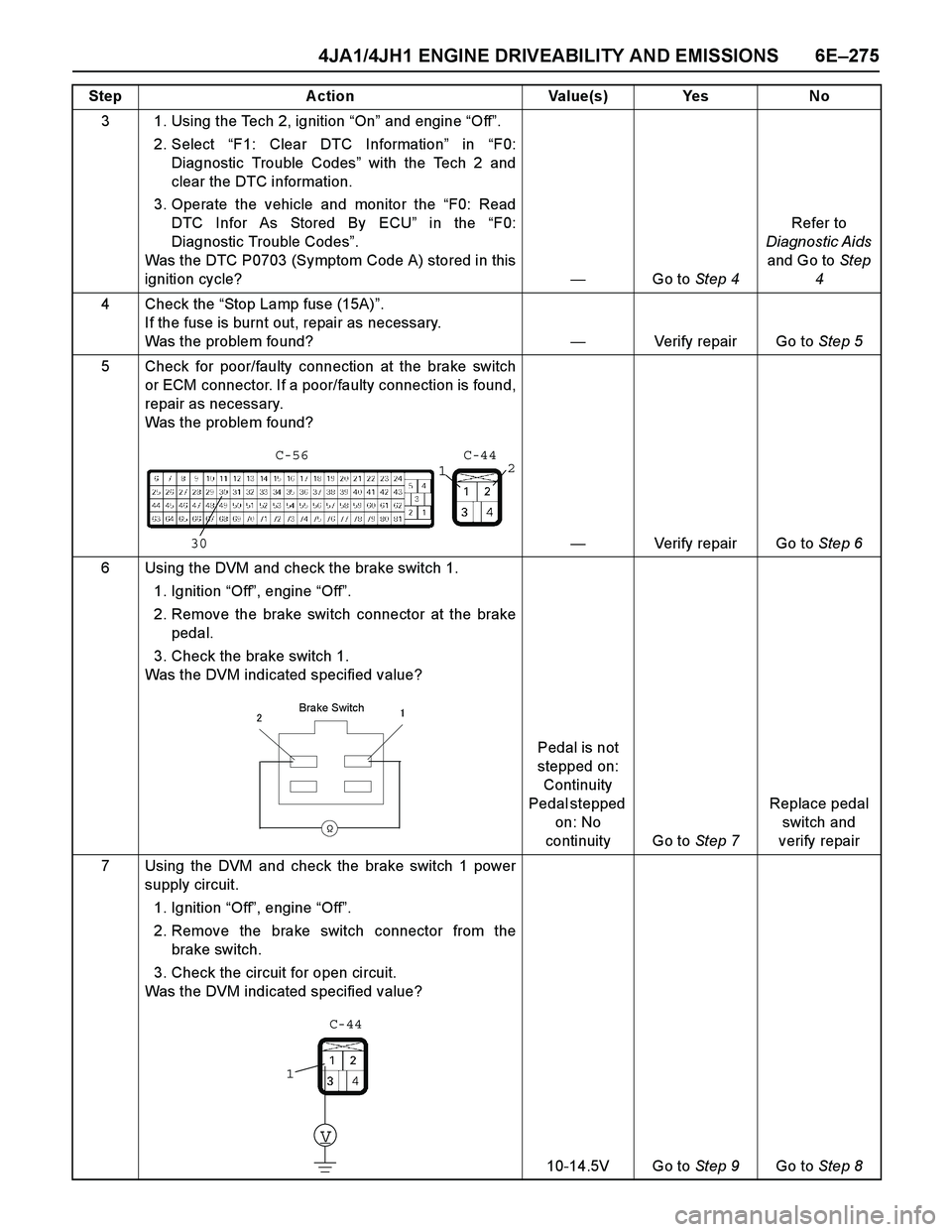
5 Check for poor/faulty connection at the brake switch
or ECM connector. If a poor/faulty connection is found,
repair as necessary.
Was the problem found?
—Verify repair Go to Step 6
6 Using the DVM and check the brake switch 1.
1. Ignition “Off”, engine “Off”.
2. Remove the brake switch connector at the brake
pedal.
3. Check the brake switch 1.
Was the DVM indicated specified value?
Pedal is not
stepped on:
Continuity
Pedal stepped
on: No
continuity Go to Step 7Replace pedal
switch and
verify repair
7 Using the DVM and check the brake switch 1 power
supply circuit.
1. Ignition “Off”, engine “Off”.
2. Remove the brake switch connector from the
brake switch.
3. Check the circuit for open circuit.
Was the DVM indicated specified value?
10-14.5V Go to Step 9Go to Step 8 Step Action Value(s) Yes No
301
2 C-56 C-44
��
�
Brake Switch
V
1C-44