2004 ISUZU TF SERIES switch
[x] Cancel search: switchPage 1494 of 4264
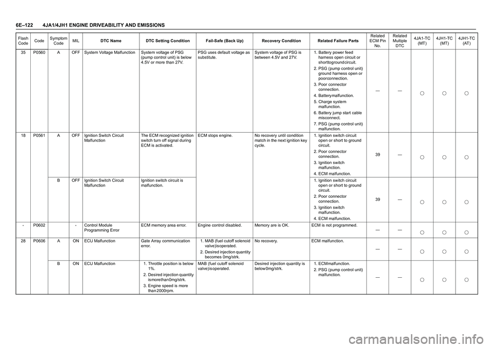
6E–122 4JA1/4JH1 ENGINE DRIVEABILITY AND EMISSIONS
35 P0560 A OFF System Voltage Malfunction System voltage of PSG
(pump control unit) is below
4.5V or more than 27V.PSG uses default voltage as
substitute.System voltage of PSG is
between 4.5V and 27V.1. Battery power feed
harness open circuit or
short to ground circuit.
2. PSG (pump control unit)
ground harness open or
p o o r c o n n e c t i o n .
3. Poor connector
c o n n e c t i o n .
4 . B a t t e r y m a l f u n c t i o n .
5. Charge system
m a l f u n c t i o n .
6. Battery jump start cable
misconnect.
7. PSG (pump control unit)
malfunction.——
18 P0561 A OFF Ignition Switch Circuit
MalfunctionThe ECM recognized ignition
switch turn off signal during
ECM is activated.ECM stops engine. No recovery until condition
match in the next ignition key
cycle.1. Ignition switch circuit
open or short to ground
c i r c u i t .
2. Poor connector
c o n n e c t i o n .
3. Ignition switch
m a l f u n c t i o n .
4. ECM malfunction.39 —
B OFF Ignition Switch Circuit
MalfunctionIgnition switch circuit is
malfunction.1. Ignition switch circuit
open or short to ground
c i r c u i t .
2. Poor connector
c o n n e c t i o n .
3. Ignition switch
m a l f u n c t i o n .
4. ECM malfunction.39 —
- P0602 - Control Module
Programming ErrorECM memory area error. Engine control disabled. Memory are is OK. ECM is not programmed.
——
28 P0606 A ON ECU Malfunction Gate Array communication
error.1. MAB (fuel cutoff solenoid
v a l v e ) i s o p e r a t e d .
2. Desired injection quantity
becomes 0mg/strk.No recovery. ECM malfunction.
——
B ON ECU Malfunction 1. Throttle position is below
1 % .
2. Desired injection quantity
is more than 0mg/strk.
3. Engine speed is more
t h a n 2 0 0 0 r p m . MAB (fuel cutoff solenoid
v a l v e ) i s o p e r a t e d . Desired injection quantity is
b e l o w 0 m g / s t r k . 1 . E C M m a l f u n c t i o n .
2. PSG (pump control unit)
malfunction.
—— Flash
CodeCodeSymptom
CodeMILDTC Name DTC Setting Condition Fail-Safe (Back Up) Recovery Condition Related Failure PartsRelated
ECM Pin
No.Related
Multiple
DTC4JA1-TC
(MT)4JH1-TC
(MT)4JH1-TC
(AT)
Page 1495 of 4264

4JA1/4JH1 ENGINE DRIVEABILITY AND EMISSIONS 6E–123
46 P0645 4 ON A/C Compressor Relay
Circuit Voltage LowA/C compressor relay circuit
open or short to ground
circuit.No fail-safe function. A/C compressor relay circuit
is correct condition.1. A/C compressor relay
circuit open or short to
g r o u n d c i r c u i t .
2. Poor connector
c o n n e c t i o n .
3. A/C compressor relay
m a l f u n c t i o n .
4. ECM malfunction.41 —
8 ON A/C Compressor Relay
Circuit Voltage High A/C compressor relay circuit
short to voltage circuit.ECM malfunction.
——
25 P0703 A ON Brake Switch Circuit
Malfunction1. Throttle position is more
t h a n 0 % .
2. Engine speed is more
than 693rpm (4JA1-TC)
or 665rpm (4JH1-TC).
3. Vehicle speed is more
t h a n 0 k m / h .
4. Brake switch 1 signal and
brake switch 2 signal are
differently inputted to the
ECM since the ignition
switch was turned on.No fail-safe function. Brake switch 1 signal and
brake switch 2 signal are
correctly inputted to the
ECM.1. Brake switch 1 circuit
open, short to ground or
short to voltage circuit.
2. Poor connector
c o n n e c t i o n .
3. Brake switch 1
m a l f u n c t i o n .
4. ECM malfunction.30 —
B ON Brake Switch Circuit
Malfunction1. Throttle position is more
t h a n 0 % .
2. Engine speed is more
than 693rpm (4JA1-TC)
or 665rpm (4JH1-TC).
3. Vehicle speed is more
t h a n 0 k m / h .
4. Brake switch 1 signal and
brake switch 2 signal are
differently inputted to the
ECM.1. Brake switch 2 circuit
open or short to ground
c i r c u i t .
2. Poor connector
c o n n e c t i o n .
3. Brake switch 2
m a l f u n c t i o n .
4. ECM malfunction.65 —
57 P0704 6 ON Clutch Switch Input Circuit
MalfunctionClutch signal does not
change between vehicle
speed 1.5km/h and 80km/h
since ignition switch was
tuned on. No fail-safe function. Clutch signal correctly
changes.1. Clutch switch circuit
open, short to ground or
short to voltage circuit.
2. Poor connector
c o n n e c t i o n .
3. Clutch switch
m a l f u n c t i o n .
4. ECM malfunction.31 — —
86 P1105 1 ON Barometric Pressure Sensor
Circuit High InputBarometric pressure sensor
output voltage is more than
4.4V.ECM uses 1013hpa
condition as substitute.Barometric pressure sensor
output voltage is below 4.4V.ECM malfunction.
——
2 ON Barometric Pressure Sensor
Circuit Low InputBarometric pressure sensor
output voltage is below 1.5V.Barometric pressure sensor
output voltage is more than
1.5V.ECM malfunction.
—— Flash
CodeCodeSymptom
CodeMILDTC Name DTC Setting Condition Fail-Safe (Back Up) Recovery Condition Related Failure PartsRelated
ECM Pin
No.Related
Multiple
DTC4JA1-TC
(MT)4JH1-TC
(MT)4JH1-TC
(AT)
Page 1496 of 4264
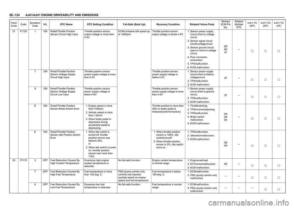
6E–124 4JA1/4JH1 ENGINE DRIVEABILITY AND EMISSIONS
21 P1120 1 ON Pedal/Throttle Position
Sensor Circuit High InputThrottle position sensor
output voltage is more than
4.5V.ECM increases idle speed up
to 1400rpm.Throttle position sensor
output voltage is below 4.5V.1. Sensor power supply
circuit short to voltage
c i r c u i t .
2. Sensor signal circuit
short to voltage circuit.
3. Sensor ground circuit
open or short to voltage
c i r c u i t .
4. Poor connector
c o n n e c t i o n .
5 . T P S m a l f u n c t i o n .
6. ECM malfunction.3 8 /
4 9 /
57—
7 ON Pedal/Throttle Position
Sensor Voltage Supply
Circuit High InputThrottle position sensor
power supply voltage is more
than 5.2V.Throttle position sensor
power supply voltage is
below 5.2V.1. Sensor power supply
circuit short to battery
voltage circuit.
2 . T P S m a l f u n c t i o n .
3. ECM malfunction.57 —
9 ON Pedal/Throttle Position
Sensor Voltage Supply
Circuit Low InputThrottle position sensor
power supply voltage is
below 4.6V.Throttle position sensor
power supply voltage is more
than 4.6V.1. Sensor power supply
circuit short to ground
c i r c u i t .
2 . T P S m a l f u n c t i o n .
3. ECM malfunction.57 —
D ON Pedal/Throttle Position
Sensor Brake Switch Error1. Engine speed is more
t h a n 1 7 0 0 r p m .
2. Vehicle speed is more
t h a n 1 . 5 k m / h .
3. When brake pedal is
depressed during
accelerator pedal is
d e p r e s s i n g . Throttle position is more than
20% or brake pedal is
released (switch is inactive). 1 . T h r o t t l e s t i c k i n g .
2. TPS incorrect adjusting.
3 . T P S m a l f u n c t i o n .
4. Brake switch
m a l f u n c t i o n .
5. ECM malfunction.3 0 /
3 8 /
65—
E ON Pedal/Throttle Position
Sensor Idle Position Switch
Error1. When idle switch is
turned off, throttle
position sensor was
b e l o w 0 . 3 5 % .
o r
2. When idle switch is tuned
on, throttle position
sensor was more than
7.8%.1. When throttle position
sensor is 100%, idle
s w i t c h t u r n s o f f .
2. When throttle position
sensor is 0%, idle switch
turns on.1 . T P S m a l f u n c t i o n .
2. Idle switch malfunction.
3. ECM malfunction.
3 8 /
69—
22 P1173 3 OFF Fuel Reduction Caused By
High Coolant TemperatureExcessive high engine
coolant temperature is
detected.No fail-safe function. Engine coolant temperature
is normal range.1 . E n g i n e o v e r h e a t .
2. ECT sensor malfunction.
3. ECM malfunction.89 —
7 OFF Fuel Reduction Caused By
High Fuel TemperatureFuel temperature is more
than 100 deg. C.PSG (pump control unit)
controls fuel injection
quantity based on engine
speed and fuel temperature.Fuel temperature is below
100 deg. C.1 . E C M m a l f u n c t i o n .
2. PSG (pump control unit)
malfunction.——
A OFF Fuel Reduction Caused By
Low Fuel TemperatureExcessive low fuel
temperature is detected.No fail-safe function. Fuel temperature is normal
range.1 . E C M m a l f u n c t i o n .
2. PSG (pump control unit)
malfunction.——— Flash
CodeCodeSymptom
CodeMILDTC Name DTC Setting Condition Fail-Safe (Back Up) Recovery Condition Related Failure PartsRelated
ECM Pin
No.Related
Multiple
DTC4JA1-TC
(MT)4JH1-TC
(MT)4JH1-TC
(AT)
Page 1497 of 4264
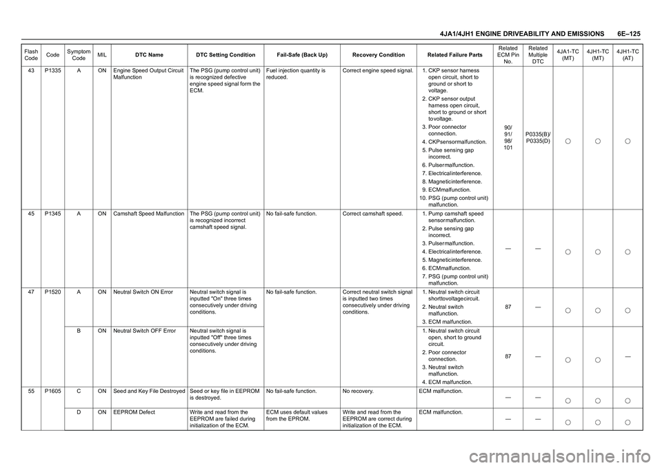
4JA1/4JH1 ENGINE DRIVEABILITY AND EMISSIONS 6E–125
43 P1335 A ON Engine Speed Output Circuit
MalfunctionThe PSG (pump control unit)
is recognized defective
engine speed signal form the
ECM.Fuel injection quantity is
reduced.Correct engine speed signal. 1. CKP sensor harness
open circuit, short to
ground or short to
voltage.
2. CKP sensor output
harness open circuit,
short to ground or short
t o v o l t a g e .
3. Poor connector
c o n n e c t i o n .
4. CKP sensor malfunction.
5. Pulse sensing gap
i n c o r r e c t .
6 . P u l s e r m a l f u n c t i o n .
7. Electrical interference.
8. Magnetic interference.
9. ECM malfunction.
10. PSG (pump control unit)
malfunction.9 0 /
9 1 /
9 8 /
101P0335(B)/
P0335(D)
45 P1345 A ON Camshaft Speed Malfunction The PSG (pump control unit)
is recognized incorrect
camshaft speed signal.No fail-safe function. Correct camshaft speed. 1. Pump camshaft speed
s e n s o r m a l f u n c t i o n .
2. Pulse sensing gap
i n c o r r e c t .
3 . P u l s e r m a l f u n c t i o n .
4. Electrical interference.
5. Magnetic interference.
6. ECM malfunction.
7. PSG (pump control unit)
malfunction.——
47 P1520 A ON Neutral Switch ON Error Neutral switch signal is
inputted "On" three times
consecutively under driving
conditions.No fail-safe function. Correct neutral switch signal
is inputted two times
consecutively under driving
conditions.1. Neutral switch circuit
short to voltage circuit.
2. Neutral switch
m a l f u n c t i o n .
3. ECM malfunction.87 —
B ON Neutral Switch OFF Error Neutral switch signal is
inputted "Off" three times
consecutively under driving
conditions.1. Neutral switch circuit
open, short to ground
c i r c u i t .
2. Poor connector
c o n n e c t i o n .
3. Neutral switch
m a l f u n c t i o n .
4. ECM malfunction.87 — —
55 P1605 C ON Seed and Key File Destroyed Seed or key file in EEPROM
is destroyed.No fail-safe function. No recovery. ECM malfunction.
——
D ON EEPROM Defect Write and read from the
EEPROM are failed during
initialization of the ECM.ECM uses default values
from the EPROM.Write and read from the
EEPROM are correct during
initialization of the ECM.ECM malfunction.
—— Flash
CodeCodeSymptom
CodeMILDTC Name DTC Setting Condition Fail-Safe (Back Up) Recovery Condition Related Failure PartsRelated
ECM Pin
No.Related
Multiple
DTC4JA1-TC
(MT)4JH1-TC
(MT)4JH1-TC
(AT)
Page 1498 of 4264
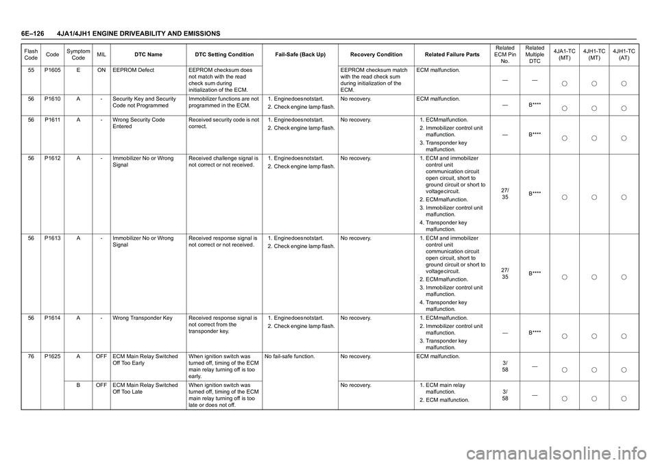
6E–126 4JA1/4JH1 ENGINE DRIVEABILITY AND EMISSIONS
55 P1605 E ON EEPROM Defect EEPROM checksum does
not match with the read
check sum during
initialization of the ECM.EEPROM checksum match
with the read check sum
during initialization of the
ECM.ECM malfunction.
——
56 P1610 A - Security Key and Security
Code not ProgrammedImmobilizer functions are not
programmed in the ECM.1 . E n g i n e d o e s n o t s t a r t .
2. Check engine lamp flash. No recovery. ECM malfunction.
— B****
56 P1611 A - Wrong Security Code
EnteredReceived security code is not
correct.1 . E n g i n e d o e s n o t s t a r t .
2. Check engine lamp flash. N o r e c o v e r y . 1 . E C M m a l f u n c t i o n .
2. Immobilizer control unit
m a l f u n c t i o n .
3. Transponder key
malfunction.— B****
56 P1612 A - Immobilizer No or Wrong
SignalReceived challenge signal is
not correct or not received.1 . E n g i n e d o e s n o t s t a r t .
2. Check engine lamp flash. No recovery. 1. ECM and immobilizer
control unit
communication circuit
open circuit, short to
ground circuit or short to
voltage circuit.
2 . E C M m a l f u n c t i o n .
3. Immobilizer control unit
m a l f u n c t i o n .
4. Transponder key
malfunction.2 7 /
35B****
56 P1613 A - Immobilizer No or Wrong
SignalReceived response signal is
not correct or not received.1 . E n g i n e d o e s n o t s t a r t .
2. Check engine lamp flash. No recovery. 1. ECM and immobilizer
control unit
communication circuit
open circuit, short to
ground circuit or short to
voltage circuit.
2 . E C M m a l f u n c t i o n .
3. Immobilizer control unit
m a l f u n c t i o n .
4. Transponder key
malfunction.2 7 /
35B****
56 P1614 A - Wrong Transponder Key Received response signal is
not correct from the
transponder key.1 . E n g i n e d o e s n o t s t a r t .
2. Check engine lamp flash. N o r e c o v e r y . 1 . E C M m a l f u n c t i o n .
2. Immobilizer control unit
m a l f u n c t i o n .
3. Transponder key
malfunction.— B****
76 P1625 A OFF ECM Main Relay Switched
Off Too EarlyWhen ignition switch was
turned off, timing of the ECM
main relay turning off is too
early.No fail-safe function. No recovery. ECM malfunction.
3 /
58—
B OFF ECM Main Relay Switched
Off Too LateWhen ignition switch was
turned off, timing of the ECM
main relay turning off is too
late or does not off.No recovery. 1. ECM main relay
m a l f u n c t i o n .
2. ECM malfunction.3 /
58— Flash
CodeCodeSymptom
CodeMILDTC Name DTC Setting Condition Fail-Safe (Back Up) Recovery Condition Related Failure PartsRelated
ECM Pin
No.Related
Multiple
DTC4JA1-TC
(MT)4JH1-TC
(MT)4JH1-TC
(AT)
Page 1543 of 4264
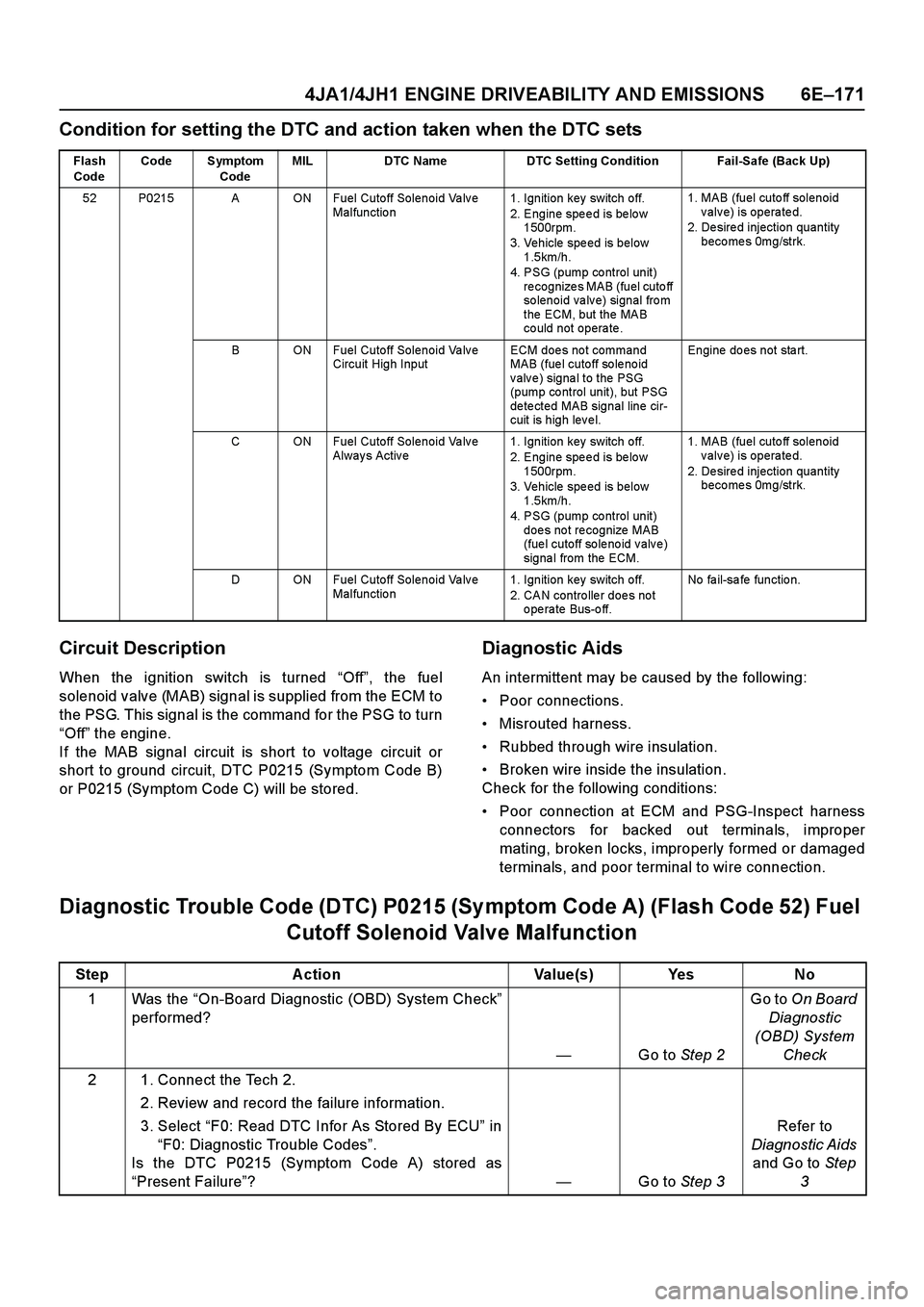
4JA1/4JH1 ENGINE DRIVEABILITY AND EMISSIONS 6E–171
Condition for setting the DTC and action taken when the DTC sets
Circuit Description
When the ignition switch is turned “Off”, the fuel
solenoid valve (MAB) signal is supplied from the ECM to
the PSG. This signal is the command for the PSG to turn
“Off” the engine.
If the MAB signal circuit is short to voltage circuit or
short to ground circuit, DTC P0215 (Symptom Code B)
or P0215 (Symptom Code C) will be stored.
Diagnostic Aids
An intermittent may be caused by the following:
Poor connections.
Misrouted harness.
Rubbed through wire insulation.
Broken wire inside the insulation.
Check for the following conditions:
Poor connection at ECM and PSG-Inspect harness
connectors for backed out terminals, improper
mating, broken locks, improperly formed or damaged
terminals, and poor terminal to wire connection.
Diagnostic Trouble Code (DTC) P0215 (Sy mptom Code A) (Flash Code 52) Fuel
Cutoff Solenoid Valve Malfunction
Flash
CodeCode Symptom
CodeMIL DTC Name DTC Setting Condition Fail-Safe (Back Up)
52 P0215 A ON Fuel Cutoff Solenoid Valve
Malfunctio n1. Ignition key switch off.
2. Engine spe e d is be lo w
1500rpm.
3. Vehicle speed is below
1.5km/h.
4. PSG (pump co ntrol unit)
recognizes MAB (fuel cutoff
solenoid valve) signal from
the ECM, but the MAB
could not operate. 1. MAB (fuel cutoff solenoid
valve) is operated.
2. Desired injection quantity
becomes 0mg/strk.
B ON Fuel Cutoff Solenoid Valve
Circuit High InputECM does not command
MAB (fue l cutoff so le no id
valve) signal to the PSG
(pump co ntrol unit), but PSG
detected MAB signal line cir-
cuit is high level.Engine do es not sta rt.
C ON Fuel Cutoff Solenoid Valve
Always Active1. Ignition key switch off.
2. Engine spe e d is be lo w
1500rpm.
3. Vehicle speed is below
1.5km/h.
4. PSG (pump co ntrol unit)
does not recognize MAB
(fue l cutoff so le no id v alv e )
signa l from the ECM. 1. MAB (fuel cutoff solenoid
valve) is operated.
2. Desired injection quantity
becomes 0mg/strk.
D ON Fuel Cutoff Solenoid Valve
Malfunctio n1. Ignition key switch off.
2. CAN contro lle r doe s no t
operate Bus-off.No fa il-sa fe fun ctio n.
Step Action Value(s) Yes No
1Was the “On-Board Diagnostic (OBD) System Check”
performed?
—Go to Step 2Go to On Board
Diagnostic
(OBD) System
Check
2 1. Connect the Tech 2.
2. Review and record the failure information.
3. Select “F0: Read DTC Infor As Stored By ECU” in
“F0: Diagnostic Trouble Codes”.
Is the DTC P0215 (Symptom Code A) stored as
“Present Failure”?—Go to Step 3Refer to
Diagnostic Aids
and Go to Step
3
Page 1551 of 4264
4JA1/4JH1 ENGINE DRIVEABILITY AND EMISSIONS 6E–179
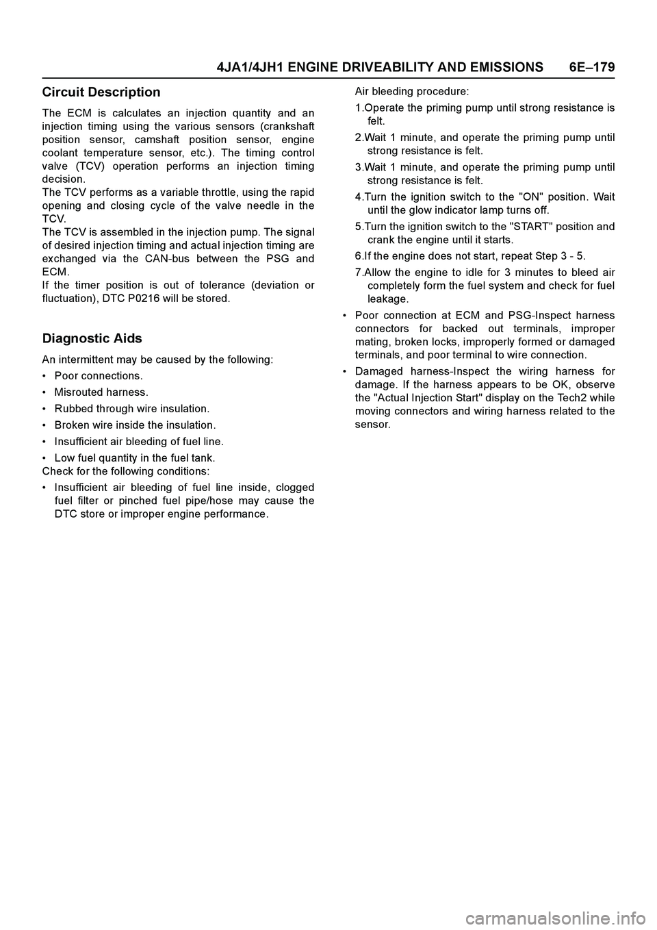
Circuit Description
The ECM is calculates an injection quantity and an
injection timing using the various sensors (crankshaft
position sensor, camshaft position sensor, engine
coolant temperature sensor, etc.). The timing control
valve (TCV) operation performs an injection timing
decision.
The TCV performs as a variable throttle, using the rapid
opening and closing cycle of the valve needle in the
TCV.
The TCV is assembled in the injection pump. The signal
of desired injection timing and actual injection timing are
ex changed via the CAN-bus between the PSG and
ECM.
If the timer position is out of tolerance (deviation or
fluctuation), DTC P0216 will be stored.
Diagnostic Aids
An intermittent may be caused by the following:
Poor connections.
Misrouted harness.
Rubbed through wire insulation.
Broken wire inside the insulation.
Insufficient air bleeding of fuel line.
Low fuel quantity in the fuel tank.
Check for the following conditions:
Insufficient air bleeding of fuel line inside, clogged
fuel filter or pinched fuel pipe/hose may cause the
DTC store or improper engine performance.Air bleeding procedure:
1.Operate the priming pump until strong resistance is
felt.
2.Wait 1 minute, and operate the priming pump until
strong resistance is felt.
3.Wait 1 minute, and operate the priming pump until
strong resistance is felt.
4.Turn the ignition switch to the "ON" position. Wait
until the glow indicator lamp turns off.
5.Turn the ignition switch to the "START" position and
crank the engine until it starts.
6.If the engine does not start, repeat Step 3 - 5.
7.Allow the engine to idle for 3 minutes to bleed air
completely form the fuel system and check for fuel
leakage.
Poor connection at ECM and PSG-Inspect harness
connectors for backed out terminals, improper
mating, broken locks, improperly formed or damaged
terminals, and poor terminal to wire connection.
Damaged harness-Inspect the wiring harness for
damage. If the harness appears to be OK, observe
the "Actual Injection Start" display on the Tech2 while
moving connectors and wiring harness related to the
sensor.
Page 1552 of 4264
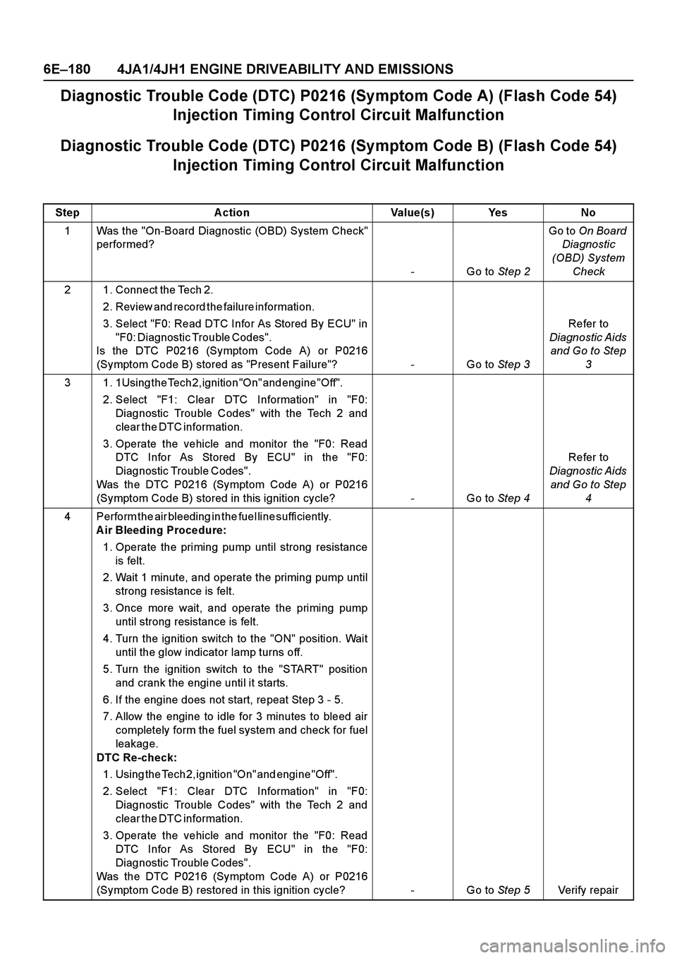
6E–180 4JA1/4JH1 ENGINE DRIVEABILITY AND EMISSIONS
Diagnostic Trouble Code (DTC) P0216 (Symptom Code A) (Flash Code 54)
Injection Timing Control Circuit Malfunction
Diagnostic Trouble Code (DTC) P0216 (Symptom Code B) (Flash Code 54)
Injection Timing Control Circuit Malfunction
Step Action Value(s) Yes No
1 Was the "On-Board Diagnostic (OBD) System Check"
performed?
-Go to Step 2Go to On Board
Diagnostic
(OBD) System
Check
2 1. Connect the Tech 2.
2. Review and record the failure information.
3. Select "F0: Read DTC Infor As Stored By ECU" in
"F0: Diagnostic Trouble Codes".
Is the DTC P0216 (Symptom Code A) or P0216
(Symptom Code B) stored as "Present Failure"? - Go to Step 3Refer to
Diagnostic Aids
and Go to Step
3
3 1. 1Using the Tech 2, ignition "On" and engine "Off".
2. Select "F1: Clear DTC Information" in "F0:
Diagnostic Trouble Codes" with the Tech 2 and
c l e a r t h e D T C i n f o r m a t i o n .
3. Operate the vehicle and monitor the "F0: Read
DTC Infor As Stored By ECU" in the "F0:
Diagnostic Trouble Codes".
Was the DTC P0216 (Symptom Code A) or P0216
(Symptom Code B) stored in this ignition cycle? - Go to Step 4Refer to
Diagnostic Aids
and Go to Step
4
4 Perform the air bleeding in the fuel line sufficiently.
A ir Bleeding Procedure:
1. Operate the priming pump until strong resistance
is felt.
2. Wait 1 minute, and operate the priming pump until
strong resistance is felt.
3. Once more wait, and operate the priming pump
until strong resistance is felt.
4. Turn the ignition switch to the "ON" position. Wait
until the glow indicator lamp turns off.
5. Turn the ignition switch to the "START" position
and crank the engine until it starts.
6. If the engine does not start, repeat Step 3 - 5.
7. Allow the engine to idle for 3 minutes to bleed air
completely form the fuel system and check for fuel
leakage.
DTC Re-check:
1. Using the Tech 2, ignition "On" and engine "Off".
2. Select "F1: Clear DTC Information" in "F0:
Diagnostic Trouble Codes" with the Tech 2 and
c l e a r t h e D T C i n f o r m a t i o n .
3. Operate the vehicle and monitor the "F0: Read
DTC Infor As Stored By ECU" in the "F0:
Diagnostic Trouble Codes".
Was the DTC P0216 (Symptom Code A) or P0216
(Symptom Code B) restored in this ignition cycle? - Go to Step 5Verify repair