Page 2241 of 4264
3.5L ENGINE DRIVEABILITY AND EMISSIONS 6E-245
Step Action Value (s) Yes No
5
If a oscilloscope is available, monitor the CMP sensor
signal. Does the oscilloscope indicate correct wave
form?
Camshaft Position (CMP) Sensor Reference Wave Form
0V
Measurement Terminal: B28(+) B39(-)
Measurement Scale: 5V/div 10ms/div
Measurement Condition: Approximately 2000rpm
Refer to
Diagnostic Aids
and Go to Step
17 Not available:
Go to Step 6
Fixed at low:
Go to Step 6
Fixed at High:
Go to Step 12
6
Check for poor/faulty connection at the TPS, CMP
sensor or ECM connector. If a poor/faulty connection is
found, repair the faulty terminal.
Was the problem found?
E-61(B)����
��E-68
�
�
�
E-62
��
�
- Verify repair Go to Step 7
7
Remove the CMP sensor from the cylinder head and
visually check.
� Objects sticking the CMP sensor.
Was the problem found?
- Verify repair Go to Step 8
Page 2256 of 4264

6E-260 3.5L ENGINE DRIVEABILITY AND EMISSIONS
Step Action Value (s) Yes No
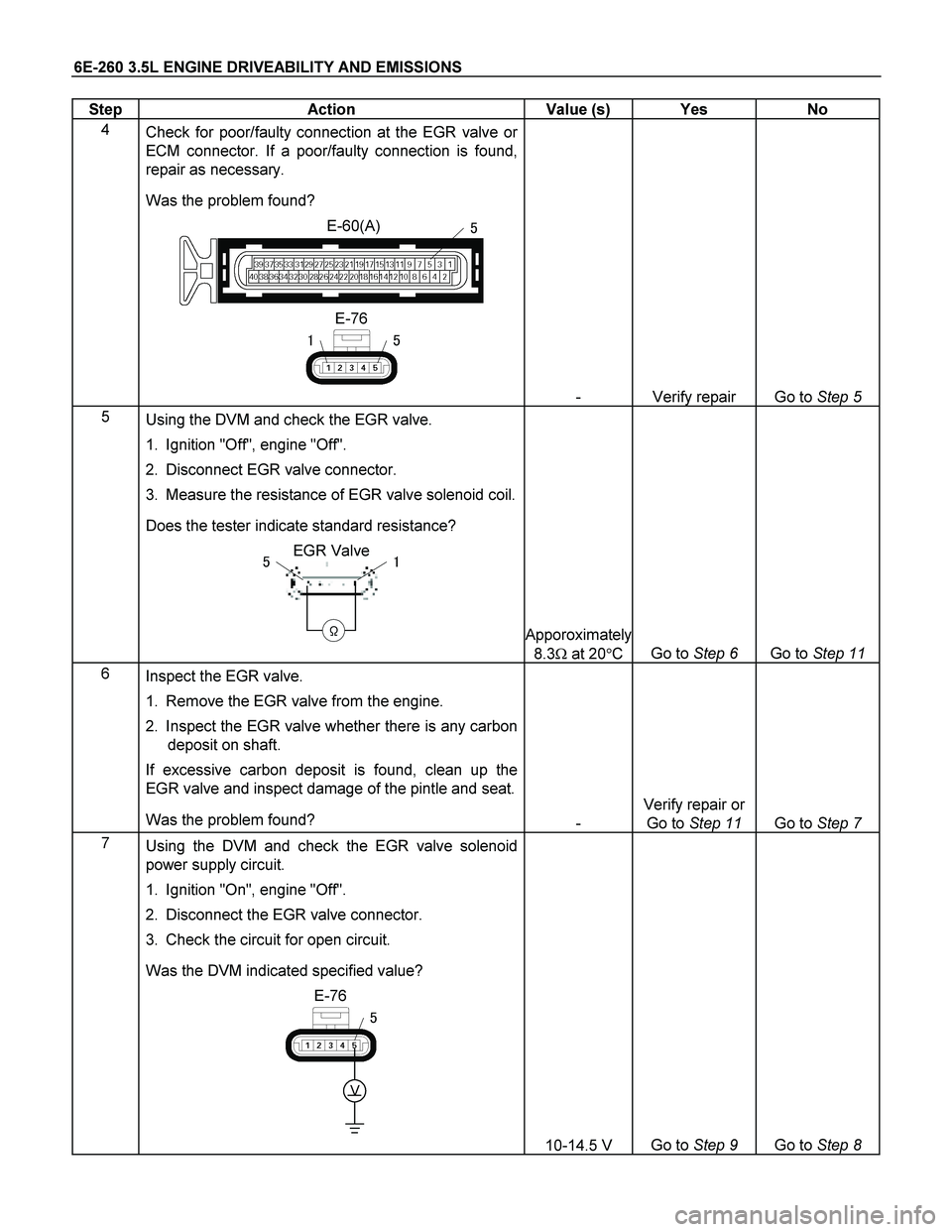
4
Check for poor/faulty connection at the EGR valve or
ECM connector. If a poor/faulty connection is found,
repair as necessary.
Was the problem found?
E-60(A)
E-76
�
��
- Verify repair Go to Step 5
5
Using the DVM and check the EGR valve.
1. Ignition "Off", engine "Off".
2. Disconnect EGR valve connector.
3. Measure the resistance of EGR valve solenoid coil.
Does the tester indicate standard resistance?
EGR Valve
�
��
Apporoximately
8.3� at 20�C
Go to Step 6
Go to Step 11
6
Inspect the EGR valve.
1. Remove the EGR valve from the engine.
2. Inspect the EGR valve whether there is any carbon
deposit on shaft.
If excessive carbon deposit is found, clean up the
EGR valve and inspect damage of the pintle and seat.
Was the problem found?
-
Verify repair or
Go to Step 11
Go to Step 7
7
Using the DVM and check the EGR valve solenoid
power supply circuit.
1. Ignition "On", engine "Off".
2. Disconnect the EGR valve connector.
3. Check the circuit for open circuit.
Was the DVM indicated specified value?
E-76
V
�
10-14.5 V
Go to Step 9
Go to Step 8
Page 2276 of 4264

6E-280 3.5L ENGINE DRIVEABILITY AND EMISSIONS
Diagnostic Trouble Code (DTC) P0500 (Flash Code 24) Vehicle Speed Sensor
(VSS) Circuit Range/Performance
Step Action Value (s) Yes No
1
Was the "On-Board Diagnostic (OBD) System Check"
performed?
- Go to Step 2 Go to On Board
Diagnostic
(OBD) System
Check
2
1. Connect the Tech 2.
2. Review and record the failure information.
3. Select "F0: Read DTC Infor By Priority" in "F0:
Diagnostic Trouble Code".
Is the DTC P0500 stored as "Present Failure"?
- Go to Step 3 Refer to
Diagnostic Aids
and Go to Step 3
3
1. Using the Tech2, ignition "On" and engine "Off".
2. Select "Clear DTC Information" with the Tech2 and
clear the DTC information.
3. Operate the vehicle and monitor the "F5: Failed This
Ignition" in "F2: DTC Information"
Was the DTC P0500 stored in this ignition cycle?
- Go to Step 4 Refer to
Diagnostic Aids
and Go to Step 4
4
Check any accessory parts which may cause electric
interference or magnetic interference.
Was the problem found?
- Remove the
accessory parts
and verify repair Go to Step 5
5
Perform test drive and check the speed meter.
Does the speed meter indicate correct vehicle speed.
- Go to Step 6 Go to Step 7
6
Perform test drive and use the Tech 2.
Monitor the "Vehicle Speed" in the data display.
Does the Tech 2 indicate correct vehicle speed as
same as the speed meter indication in the instrument
panel?
- Go to Step 25 Go to Step 8
7
Check for poor/faulty connection at the VSS and meter
connectors. If a poor/faulty connection is found, repair
the faulty terminal.
Was the problem found?
B-24E-44���
����
�
�
�
- Verify repair Go to Step 9
Page 2277 of 4264
3.5L ENGINE DRIVEABILITY AND EMISSIONS 6E-281
Step Action Value (s) Yes No
8
Check for poor/faulty connection at the immobilizer
control unit (if equipped), ECM and other connectors. If
a poor/faulty connection is found, repair the faulty
terminal.
Was the problem found?
B-68
��
E-61(B)
��
- Verify repair Go to Step 10
9
Remove the VSS from the housing case and visually
check.
Was the problem found?
- Go to Step 23 Go to Step 10
Page 2295 of 4264
3.5L ENGINE DRIVEABILITY AND EMISSIONS 6E-299
Step Action Value (s) Yes No
6
Remove the IAC Valve and visually check.
Was the problem found?
- Go to Step 12 Go to Step 7
7
Using the DVM and check the IAC Valve coil at IAC
Valve.
1. Ignition "Off", engine "Off".
2. Disconnect the IAC Valve connector.
3. Check the coil resistance.
Does the tester indicate standard resistance as shown
in the following table?
IAC Valve
��
��
���
�
�
�
Measurement Terminal Resistance (�)
1 - 2 Approximately 50�
2 - 3 Approximately 50�
1 – 3 Approximately 100�
4 - 5 Approximately 50�
5 - 6 Approximately 50�
4 - 6 Approximately 100�
-
Go to Step 8
Go to Step 12
8
Using the DVM and check the IAC Valve power supply
circuit.
1. Ignition "Off", engine "Off".
2. Disconnect the IAC Valve connector and ECM
main relay
3. Check the circuit for open circuit.
Was the problem found?
X-13E-70
�
�
�
�
�
-
Repair faulty
harness and
verify repair
Go to Step 9
Page 2301 of 4264

3.5L ENGINE DRIVEABILITY AND EMISSIONS 6E-305
Diagnostic Trouble Code (DTC) P1601 (Flash Code 65) CAN Bus Off
Step Action Value (s) Yes No
1
Was the "On-Board Diagnostic (OBD) System Check"
performed?
- Go to Step 2 Go to On Board
Diagnostic (OBD)
System Check
2
1. Connect the Tech 2.
2. Review and record the failure information.
3. Select "F0: Read DTC Infor By Priority" in "F0:
Diagnostic Trouble Code".
Is the DTC P1601 stored as "Present Failure"?
- Go to Step 3 Refer to
Diagnostic Aids
and Go to Step 3
3
1. Using the Tech2, ignition "On" and engine "Off".
2. Select "Clear DTC Information" with the Tech2 and
clear the DTC information.
3. Operate the vehicle and monitor the "F5: Failed
This Ignition" in "F2: DTC Information"
Was the DTC P1601 stored in this ignition cycle?
- Go to Step 4 Refer to
Diagnostic Aids
and Go to Step 4
4
Check any accessory parts which may cause electric
interference.
Was the problem found?
- Remove the
accessory parts
and verify repair Go to Step 5
5
1. Using the Tech 2, ignition "On" and engine "Off".
2. Select "AW30-40LE" in the system selection menu
"Powertrain".
3. Select "Read DTC Info Ordered By Priority" in the
"Diagnositic Trouble Code".
Was the any DTC's P1767 or U2104 stored in this
ignition cycle?
- Refer to
"Automatic
Transmission
Workshop
Manual" & Go to
DTC Chart
P1767 or U2104 Go to Step 6
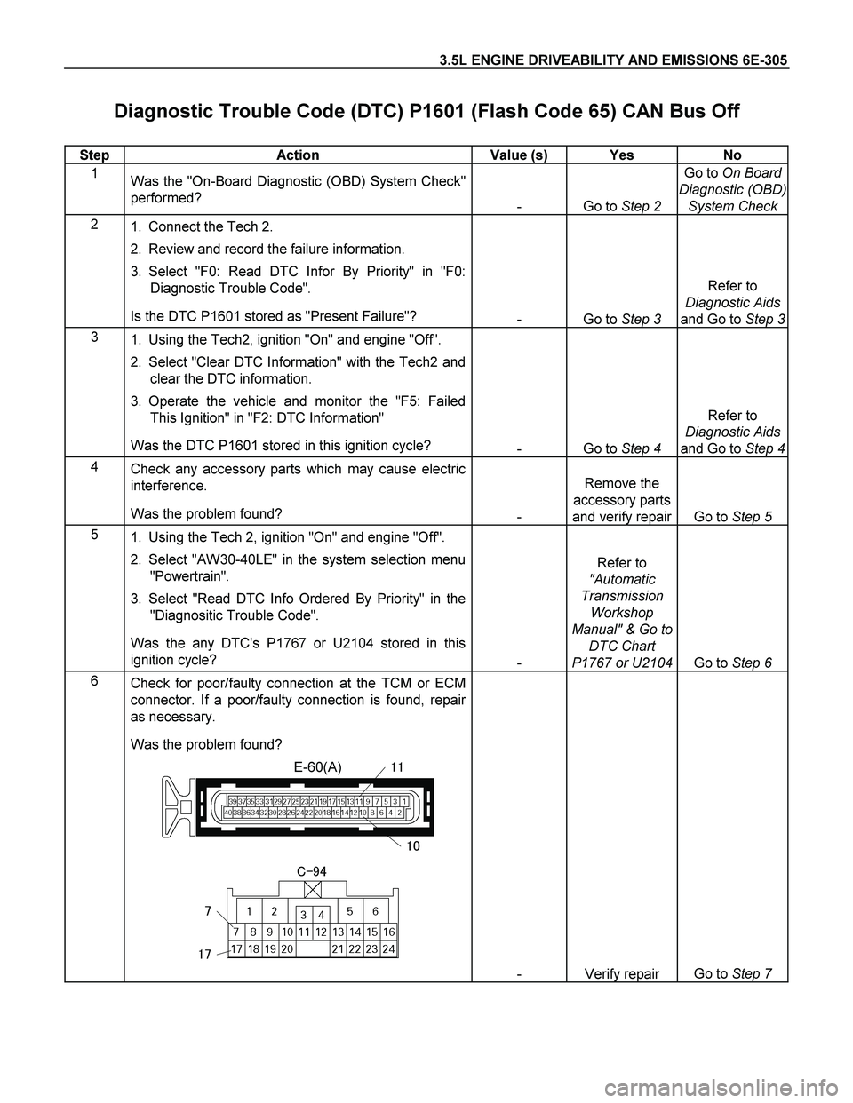
6
Check for poor/faulty connection at the TCM or ECM
connector. If a poor/faulty connection is found, repair
as necessary.
Was the problem found?
E-60(A)��
��
����
�
��
- Verify repair Go to Step 7
Page 2307 of 4264

3.5L ENGINE DRIVEABILITY AND EMISSIONS 6E-311
Diagnostic Trouble Code (DTC) U2104 (Flash Code 67) CAN Bus Reset
Counter Over-Run
Step Action Value (s) Yes No
1
Was the "On-Board Diagnostic (OBD) System Check"
performed?
- Go to Step 2 Go to On Board
Diagnostic (OBD)
System Check
2
1. Connect the Tech 2.
2. Review and record the failure information.
3. Select "F0: Read DTC Infor By Priority" in "F0:
Diagnostic Trouble Code".
Is the DTC U2104 stored as "Present Failure"?
- Go to Step 3 Refer to
Diagnostic Aids
and Go to Step 3
3
1. Using the Tech2, ignition "On" and engine "Off".
2. Select "Clear DTC Information" with the Tech2 and
clear the DTC information.
3. Operate the vehicle and monitor the "F5: Failed
This Ignition" in "F2: DTC Information"
Was the DTC U2104 stored in this ignition cycle?
- Go to Step 4 Refer to
Diagnostic Aids
and Go to Step 4
4
1. Using the Tech 2, ignition "On" and engine "Off".
2. Select "AW30-40LE" in the system selection menu
"Powertrain".
3. Select "Read DTC Info Ordered By Priority" in the
"Diagnositic Trouble Code".
Was the any DTC's P1767 or U2104 stored in this
ignition cycle?
- Refer to
"Automatic
Transmission
Workshop
Manual" & Go to
DTC Chart
P1767 or U2104 Go to Step 5
5
Check any accessory parts which may cause electric
interference.
Was the problem found?
- Remove the
accessory parts
and verify repair Go to Step 6
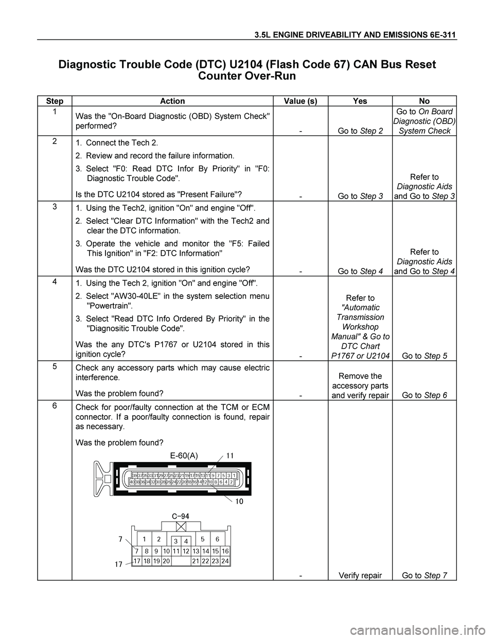
6
Check for poor/faulty connection at the TCM or ECM
connector. If a poor/faulty connection is found, repair
as necessary.
Was the problem found?
E-60(A)��
��
����
�
��
- Verify repair Go to Step 7
Page 2314 of 4264

6E-318 3.5L ENGINE DRIVEABILITY AND EMISSIONS
Diagnostic Trouble Code (DTC) P1626 Immobilizer No Signal
Step Action Value (s) Yes No
1
Was the "On-Board Diagnostic (OBD) System Check"
performed?
- Go to Step 2 Go to On Board
Diagnostic (OBD)
System Check
2
1. Connect the Tech 2.
2. Review and record the failure information.
3. Select "F0: Read DTC Infor By Priority" in "F0:
Diagnostic Trouble Code".
Is the DTC P1626 stored as "Present Failure"?
- Go to Step 3 Refer to
Diagnostic Aids
and Go to Step 3
3
1. Using the Tech2, ignition "On" and engine "Off".
2. Select "Clear DTC Information" with the Tech2 and
clear the DTC information.
3. Operate the vehicle and monitor the "F5: Failed
This Ignition" in "F2: DTC Information"
Was the DTC P1626 stored in this ignition cycle?
- Go to Step 4 Refer to
Diagnostic Aids
and Go to Step 4
4
Check any accessory parts which may cause electric
interference.
Was the problem found?
- Remove the
accessory parts
and verify repair Go to Step 5
5
1. Using the Tech 2, ignition "On" and engine "Off".
2. Select "Immobilizer" in the system selection menu
"Body".
3. Select "Read DTC Info Ordered By Priority" in the
"Diagnositic Trouble Code".
Was the DTC B0007 stored in this ignition cycle?
- Refer to
"Immobilizer
Workshop
Manual" & Go to
DTC Chart
B0007 Go to Step 6
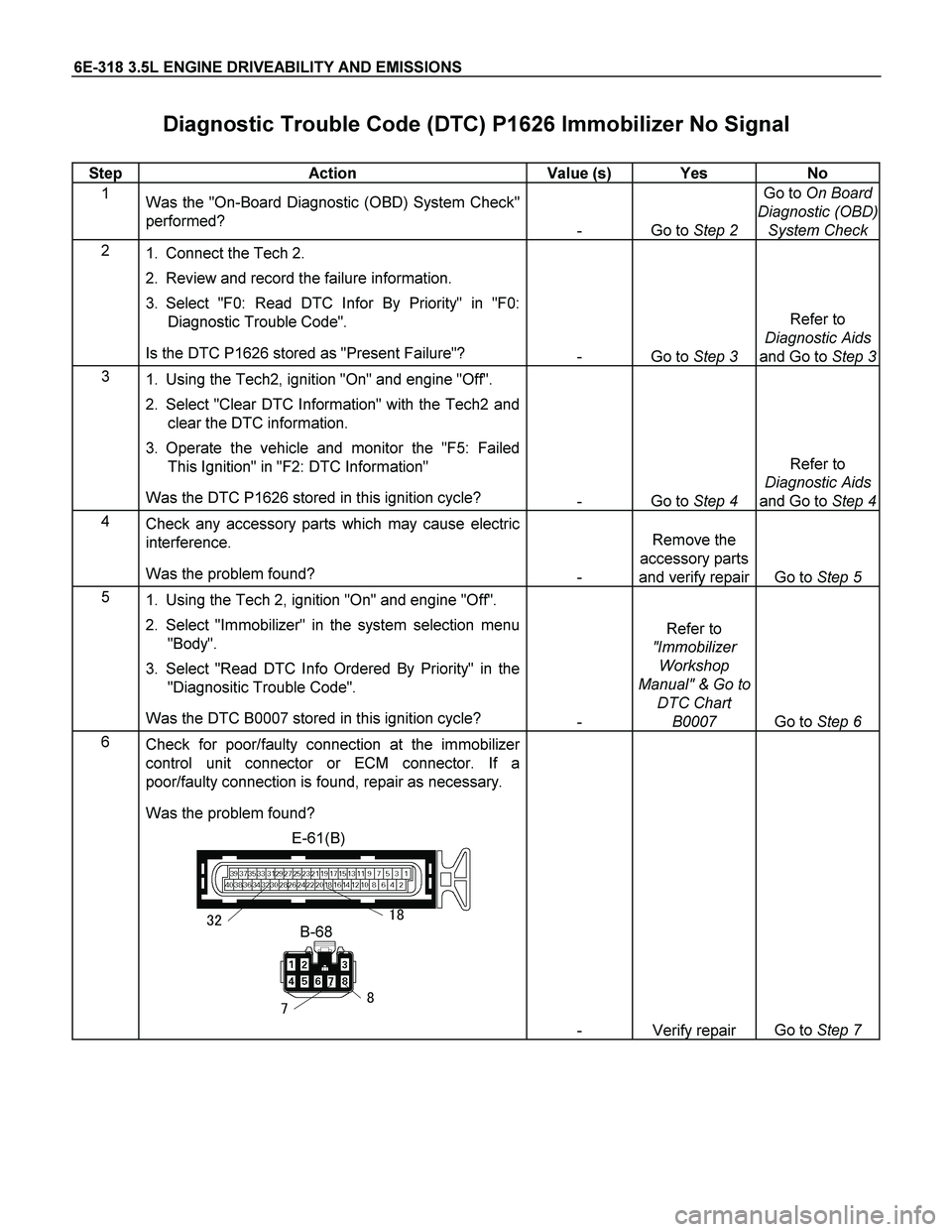
6
Check for poor/faulty connection at the immobilizer
control unit connector or ECM connector. If a
poor/faulty connection is found, repair as necessary.
Was the problem found?
E-61(B)
B-68����
��
- Verify repair Go to Step 7