Page 1968 of 4264
6D2-4 IGNITION SYSTEM (6VE1 3.5L)
Spark Plug
Inspection
Poor spark plug condition adversely affects engine
performance. Carefully inspect each spark plug
following the procedure outlined below.
1. Remove the spark plug.
2. Check the plug for dirt and other foreign material.
If the plug is extremely dirty, the fuel and electrical
systems must be checked.
3. If necessary, clean the spark plugs by placing them
in a spark plug cleaning machine for no more than
20 seconds.
4. Check the electrode and insulator for wear and/o
r
cracking. If there is significant wear or cracking, the
plug must be replaced.
5. Check the gasket for damage. Replace the gasket i
f
necessary.
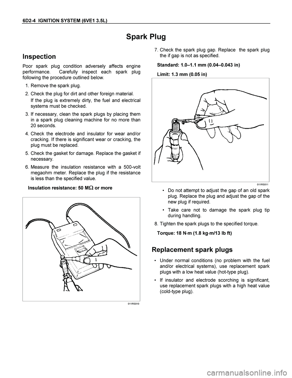
6. Measure the insulation resistance with a 500-vol
t
megaohm meter. Replace the plug if the resistance
is less than the specified value.
Insulation resistance: 50 M
�
�� � or more
011RS010
7. Check the spark plug gap. Replace the spark plug
the if gap is not as specified.
Standard: 1.0–1.1 mm (0.04–0.043 in)
Limit: 1.3 mm (0.05 in)
011RS011
Do not attempt to adjust the gap of an old spark
plug. Replace the plug and adjust the gap of the
new plug if required.
Take care not to damage the spark plug tip
during handling.
8. Tighten the spark plugs to the specified torque.
Torque: 18 N�
�� �m (1.8 kg�
�� �m/13 lb ft)
Replacement spark plugs
Under normal conditions (no problem with the fuel
and/or electrical systems), use replacement spark
plugs with a low heat value (hot-type plug).
If insulator and electrode scorching is significant,
use replacement spark plugs with a high heat value
(cold-type plug).
Page 1969 of 4264
IGNITION SYSTEM (6VE1 3.5L) 6D2-5
Crankshaft Position Sensor
Removal
1. Disconnect battery ground cable
2. Wiring connector from crankshaft position sensor.
3. Remove crankshaft position sensor from cylinde
r
block.
012RS008
Installation
1. Install crankshaft position sensor into the cylinder
block.
Before installation, apply small amount of engine
oil to the O–ring.
Torque: 10 N�
�� �m (1.0 kg�
�� �m/7 lb ft)
2. Reconnect wiring connector to crankshaft position
sensor.
Page 1977 of 4264
STARTING AND CHARGING SYSTEM (6VE1 3.5L) 6D3-5
Starter
Removal
1. Battery ground cable.
2. Disconnect left heated O
2 sensor connector.
3. Remove exhaust front left pipe.
4. Remove dust cover.
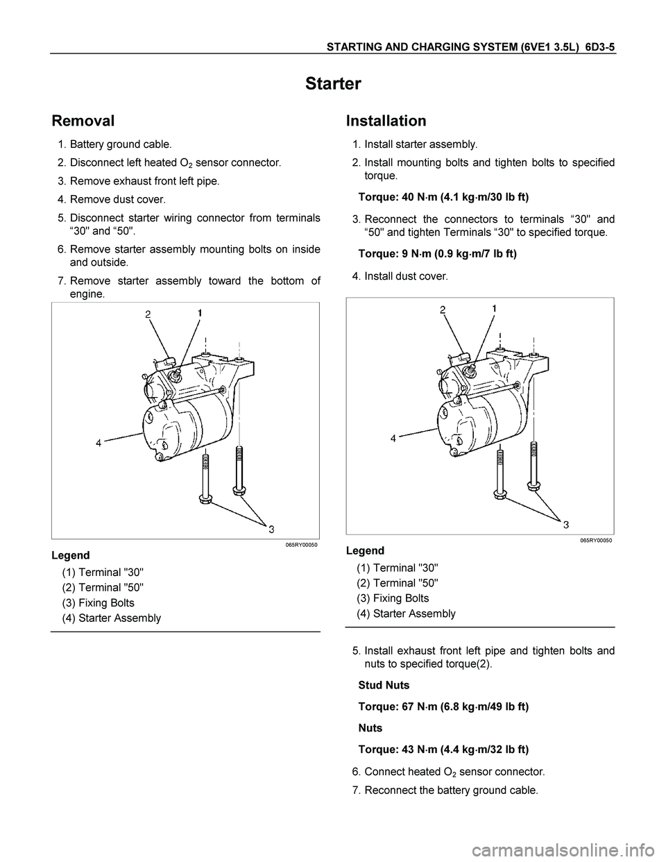
5. Disconnect starter wiring connector from terminals
“30" and “50".
6. Remove starter assembly mounting bolts on inside
and outside.
7. Remove starter assembly toward the bottom o
f
engine.
065RY00050
Legend
(1) Terminal "30"
(2) Terminal "50"
(3) Fixing Bolts
(4) Starter Assembly
Installation
1. Install starter assembly.
2. Install mounting bolts and tighten bolts to specified
torque.
Torque: 40 N�
�� �m (4.1 kg�
�� �m/30 lb ft)
3. Reconnect the connectors to terminals “30" and
“50" and tighten Terminals “30" to specified torque.
Torque: 9 N�
�� �m (0.9 kg�
�� �m/7 lb ft)
4. Install dust cover.
065RY00050
Legend
(1) Terminal "30"
(2) Terminal "50"
(3) Fixing Bolts
(4) Starter Assembly
5. Install exhaust front left pipe and tighten bolts and
nuts to specified torque(2).
Stud Nuts
Torque: 67 N�
�� �m (6.8 kg�
�� �m/49 lb ft)
Nuts
Torque: 43 N�
�� �m (4.4 kg�
�� �m/32 lb ft)
6. Connect heated O
2 sensor connector.
7. Reconnect the battery ground cable.
Page 1988 of 4264
6D3-16 STARTING AND CHARGING SYSTEM (6VE1 3.5L)
Generator
Removal
1. Disconnect battery ground cable.
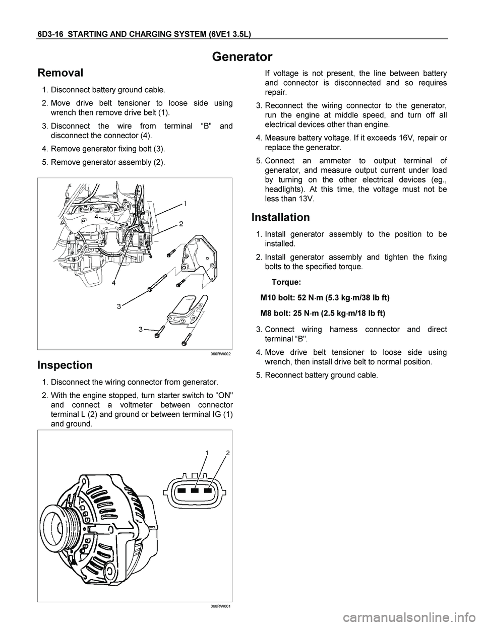
2. Move drive belt tensioner to loose side using
wrench then remove drive belt (1).
3. Disconnect the wire from terminal “B" and
disconnect the connector (4).
4. Remove generator fixing bolt (3).
5. Remove generator assembly (2).
060RW002
Inspection
1. Disconnect the wiring connector from generator.
2. With the engine stopped, turn starter switch to “ON"
and connect a voltmeter between connecto
r
terminal L (2) and ground or between terminal IG (1)
and ground.
066RW001
If voltage is not present, the line between battery
and connector is disconnected and so requires
repair.
3. Reconnect the wiring connector to the generator,
run the engine at middle speed, and turn off all
electrical devices other than engine.
4. Measure battery voltage. If it exceeds 16V, repair o
r
replace the generator.
5. Connect an ammeter to output terminal o
f
generator, and measure output current under load
by turning on the other electrical devices (eg.,
headlights). At this time, the voltage must not be
less than 13V.
Installation
1. Install generator assembly to the position to be
installed.
2. Install generator assembly and tighten the fixing
bolts to the specified torque.
Torque:
M10 bolt: 52 N�
�� �m (5.3 kg�
�� �m/38 lb ft)
M8 bolt: 25 N�
�� �m (2.5 kg�
�� �m/18 lb ft)
3. Connect wiring harness connector and direc
t
terminal “B".
4. Move drive belt tensioner to loose side using
wrench, then install drive belt to normal position.
5. Reconnect battery ground cable.
Page 2089 of 4264
3.5L ENGINE DRIVEABILITY AND EMISSIONS 6E -93
5.
After choosing the data, click the "Next" button.
6.
When all the necessary information is entered, the
"details" of software within the database that
match the entered data will appear fo
r
confirmation. Click the "Program" switch and then
download the new software onto Tech-2.
7. "Data Transfer" comes on display. The progress o
f
downloading will be displayed on the screen in the
form of bar graph.
8.
Upon finishing the data transfer, turn off the powe
r
of Tech-2, removing from P/C.
4. Programming of ECM
1.
Check to see if batteries are fully charged, while
ABS connectors shall be removed from the
vehicle.
2.
Connect Tech-2 to Vehicle Diagnostic Connectors.
3.
Turn on the power of Tech-2 and the title screen
comes on display.
4.
Turn on the ignition (without allowing the engine to
start)
5.
On the title screen of Tech-2, push the "Enter"
button.
6.
Choose "F1: Service Programming System" on the
main screen and then choose "F1: Program ECU".
7.
While data is being transferred, "Programing in
Progress" will be displayed on the Tech-2 screen.
8.
Upon finishing the data transfer, Tech-2 will
display "Reprogramming was Successful". Push
the "Exit" button to bring program to completion.
9.
Following "Procedure 2: Demand of Data", try ove
r
again "Information Obtaining" and check to confirm
if the data has been correctly re-loaded.
10. Upon finishing confirmation, turn off the ignition o
f
the vehicle and then turn off the power of Tech-2,
removing from the vehicle.
Page 2108 of 4264
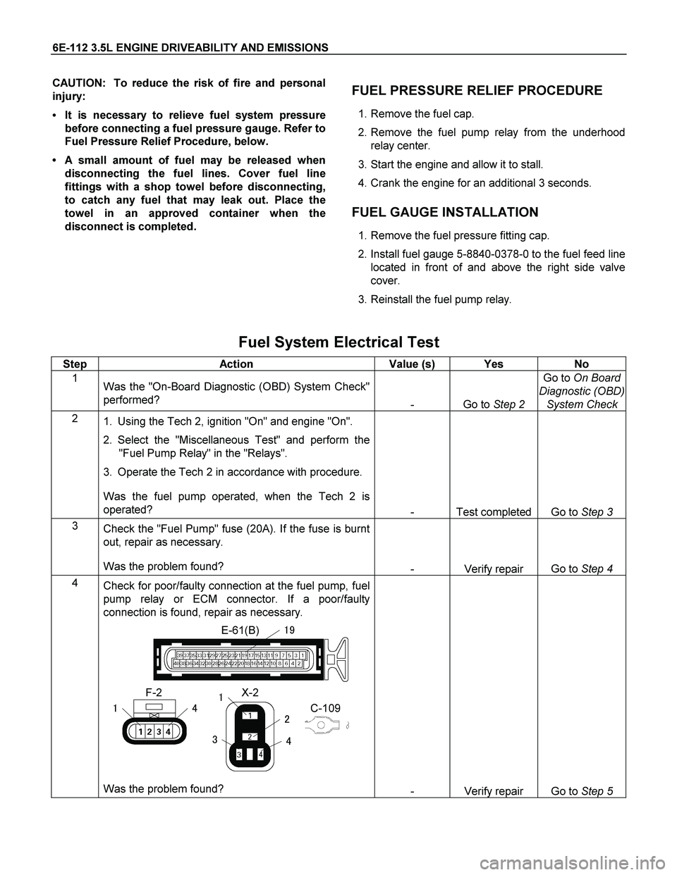
6E-112 3.5L ENGINE DRIVEABILITY AND EMISSIONS
CAUTION: To reduce the risk of fire and personal
injury:
It is necessary to relieve fuel system pressure
before connecting a fuel pressure gauge. Refer to
Fuel Pressure Relief Procedure, below.
A small amount of fuel may be released when
disconnecting the fuel lines. Cover fuel line
fittings with a shop towel before disconnecting,
to catch any fuel that may leak out. Place the
towel in an approved container when the
disconnect is completed.
FUEL PRESSURE RELIEF PROCEDURE
1. Remove the fuel cap.
2. Remove the fuel pump relay from the underhood
relay center.
3. Start the engine and allow it to stall.
4. Crank the engine for an additional 3 seconds.
FUEL GAUGE INSTALLATION
1. Remove the fuel pressure fitting cap.
2. Install fuel gauge 5-8840-0378-0 to the fuel feed line
located in front of and above the right side valve
cover.
3. Reinstall the fuel pump relay.
Fuel System Electrical Test
Step Action Value (s) Yes No
1
Was the "On-Board Diagnostic (OBD) System Check"
performed?
- Go to Step 2 Go to On Board
Diagnostic (OBD)
System Check
2
1. Using the Tech 2, ignition "On" and engine "On".
2. Select the "Miscellaneous Test" and perform the
"Fuel Pump Relay" in the "Relays".
3. Operate the Tech 2 in accordance with procedure.
Was the fuel pump operated, when the Tech 2 is
operated?
- Test completed Go to Step 3
3
Check the "Fuel Pump" fuse (20A). If the fuse is burnt
out, repair as necessary.
Was the problem found?
- Verify repair Go to Step 4
4
Check for poor/faulty connection at the fuel pump, fuel
pump relay or ECM connector. If a poor/faulty
connection is found, repair as necessary.
E-61(B)
X-2
�
F-2
C-109
��
��
�
�
�
�
Was the problem found?
- Verify repair Go to Step 5
Page 2109 of 4264
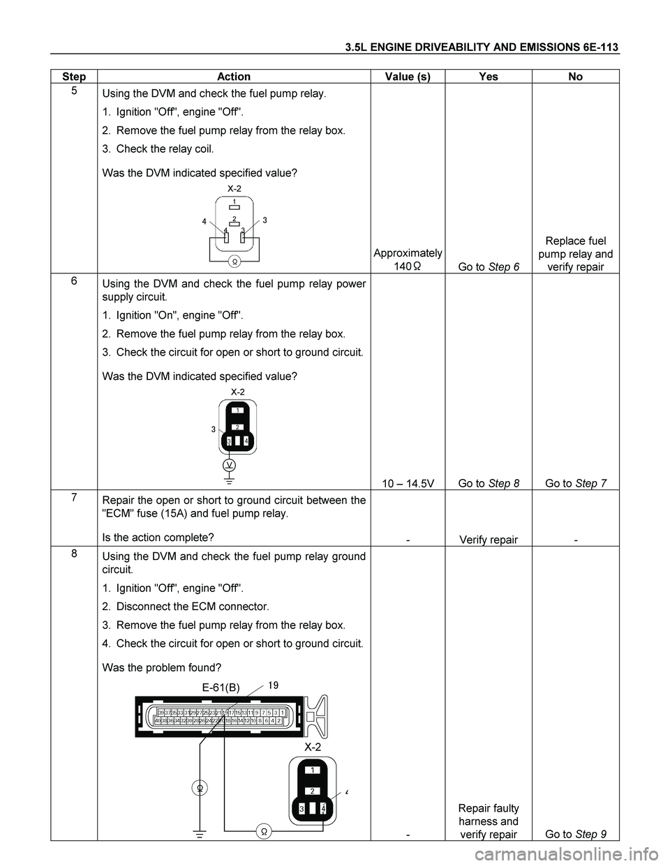
3.5L ENGINE DRIVEABILITY AND EMISSIONS 6E-113
Step Action Value (s) Yes No
5
Using the DVM and check the fuel pump relay.
1. Ignition "Off", engine "Off".
2. Remove the fuel pump relay from the relay box.
3. Check the relay coil.
Was the DVM indicated specified value?
X-2
�
1
3 2
4
�
��
Approximately
140�
Go to Step 6 Replace fuel
pump relay and
verify repair
6
Using the DVM and check the fuel pump relay power
supply circuit.
1. Ignition "On", engine "Off".
2. Remove the fuel pump relay from the relay box.
3. Check the circuit for open or short to ground circuit.
Was the DVM indicated specified value?
X-2
�
V
�
10 – 14.5V Go to Step 8 Go to Step 7
7
Repair the open or short to ground circuit between the
"ECM" fuse (15A) and fuel pump relay.
Is the action complete?
- Verify repair -
8
Using the DVM and check the fuel pump relay ground
circuit.
1. Ignition "Off", engine "Off".
2. Disconnect the ECM connector.
3. Remove the fuel pump relay from the relay box.
4. Check the circuit for open or short to ground circuit.
Was the problem found?
E-61(B)
X-2
�
�
�
�
��
- Repair faulty
harness and
verify repair Go to Step 9
Page 2110 of 4264
6E-114 3.5L ENGINE DRIVEABILITY AND EMISSIONS
Step Action Value (s) Yes No
9
Using the DVM and check the fuel pump relay power
supply circuit.
1. Ignition "Off", engine "Off".
2. Remove the fuel pump relay from the relay box.
3. Check the circuit for open circuit.
Was the DVM indicated specified value?
X-2
�V
�
10 – 14.5V Go to Step 11 Go to Step 10
10
Repair the open circuit between the fuel pump relay
and battery.
Is the action complete?
- Verify repair -
11
Using the DVM and check the fuel pump power supply
circuit.
1. Ignition "On", engine "Off".
2. Disconnect the fuel pump connector.
3. Check the circuit for open or short to ground circuit.
Was the DVM indicated specified value?
F-2
�
V
10 – 14.5V Go to Step 13 Go to Step 12
12
Repair the open or short to ground circuit between the
fuel pump relay and fuel pump.
Is the action complete?
F-2
X-2
�
��
- Verify repair -