2004 ISUZU TF SERIES sensor
[x] Cancel search: sensorPage 1633 of 4264

4JA1/4JH1 ENGINE DRIVEABILITY AND EMISSIONS 6E–261
Circuit Description
The ECM monitors the ignition switch signal on the feed
terminal to the ECM. If the ignition switch signal with
malfunction, DTC P0561 (Symptom Code A) or DTC
P0561 (Symptom Code B) will be stored.
Diagnostic Aids
An intermittent may be caused by the following:
Poor connections.
Misrouted harness.Rubbed through wire insulation.
Broken wire inside the insulation.
Check for the following conditions:
Poor connection at ECM-Inspect harness connectors
for backed out terminals, improper mating, broken
locks, improperly formed or damaged terminals, and
poor terminal to wire connection.
Damaged harness-Inspect the wiring harness for
damage. If the harness appears to be OK, observe
the “Ignition Status” display on the Tech2 while
moving connectors and wiring harness related to the
sensor.
Diagnostic Trouble Code (DTC) P0561 (Symptom Code A) (Flash Code 18)
Ignition Switch Circuit Malfunction
Diagnostic Trouble Code (DTC) P0561 (Symptom Code B) (Flash Code 18)
Ignition Switch Circuit Malfunction
Step Action Value(s) Yes No
1Was the “On-Board Diagnostic (OBD) System Check”
performed?
—Go to Step 2Go to On Board
Diagnostic
(OBD) System
Check
2 1. Connect the Tech 2.
2. Review and record the failure information.
3. Select “F0: Read DTC Infor As Stored By ECU” in
“F0: Diagnostic Trouble Codes”.
Is the DTC P0561 (Symptom Code A) or P0561
(Symptom Code B) stored as “Present Failure”?—Go to Step 3Refer to
Diagnostic Aids
and Go to Step
3
3 1. Using the Tech 2, ignition “On” and engine “Off”.
2. Select “F1: Clear DTC Information” in “F0:
Diagnostic Trouble Codes” with the Tech 2 and
clear the DTC information.
3. Operate the vehicle and monitor the “F0: Read
DTC Infor As Stored By ECU” in the “F0:
Diagnostic Trouble Codes”.
Was the DTC P0561 (Symptom Code A) or P0561
(Symptom Code B)stored in this ignition cycle?—Go to Step 4Refer to
Diagnostic Aids
and Go to Step
4
4 Check the “Engine fuse (10A)”.
If the fuse is burnt out, repair as necessary.
Was the problem found?—Verify repair Go to Step 5
Page 1646 of 4264
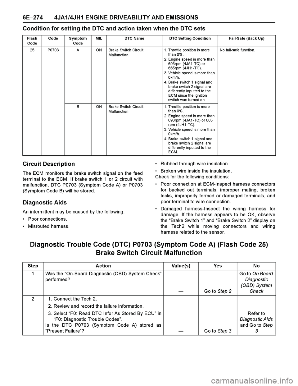
6E–274 4JA1/4JH1 ENGINE DRIVEABILITY AND EMISSIONS
Condition for setting the DTC and action taken when the DTC sets
Circuit Description
The ECM monitors the brake switch signal on the feed
terminal to the ECM. If brake switch 1 or 2 circuit with
malfunction, DTC P0703 (Symptom Code A) or P0703
(Symptom Code B) will be stored.
Diagnostic Aids
An intermittent may be caused by the following:
Poor connections.
Misrouted harness.Rubbed through wire insulation.
Broken wire inside the insulation.
Check for the following conditions:
Poor connection at ECM-Inspect harness connectors
for backed out terminals, improper mating, broken
locks, improperly formed or damaged terminals, and
poor terminal to wire connection.
Damaged harness-Inspect the wiring harness for
damage. If the harness appears to be OK, observe
the “Brake Switch 1” and “Brake Switch 2” display on
the Tech2 while moving connectors and wiring
harness related to the sensor.
Diagnostic Trouble Code (DTC) P0703 (Symptom Code A) (Flash Code 25)
Brake Switch Circuit Malfunction
Flash
CodeCode Symptom
CodeMIL DTC Name DTC Setting Condition Fail-Safe (Back Up)
25 P0703 A ON Bra ke Switch Circuit
Malfunctio n1. Thro ttle po sitio n is more
tha n 0%.
2. Engine speed is more than
693rpm (4JA1-TC) or
665rpm (4JH1-TC).
3. Vehicle speed is more than
0km/h.
4. Brake switch 1 signal and
brake switch 2 signal are
differently inputted to the
ECM since the ignition
sw it ch w a s tur ne d o n.No fa il-sa fe fun ctio n.
B ON Bra ke Switch Circuit
Malfunctio n1. Thro ttle po sitio n is more
tha n 0%.
2. Engine speed is more than
693rpm (4JA1-TC) or 665
rpm (4JH1-TC).
3. Vehicle speed is more than
0km/h.
4. Brake switch 1 signal and
brake switch 2 signal are
differently inputted to the
ECM.
Step Action Value(s) Yes No
1Was the “On-Board Diagnostic (OBD) System Check”
performed?
—Go to Step 2Go to On Board
Diagnostic
(OBD) System
Check
2 1. Connect the Tech 2.
2. Review and record the failure information.
3. Select “F0: Read DTC Infor As Stored By ECU” in
“F0: Diagnostic Trouble Codes”.
Is the DTC P0703 (Symptom Code A) stored as
“Present Failure”?—Go to Step 3Refer to
Diagnostic Aids
and Go to Step
3
Page 1653 of 4264
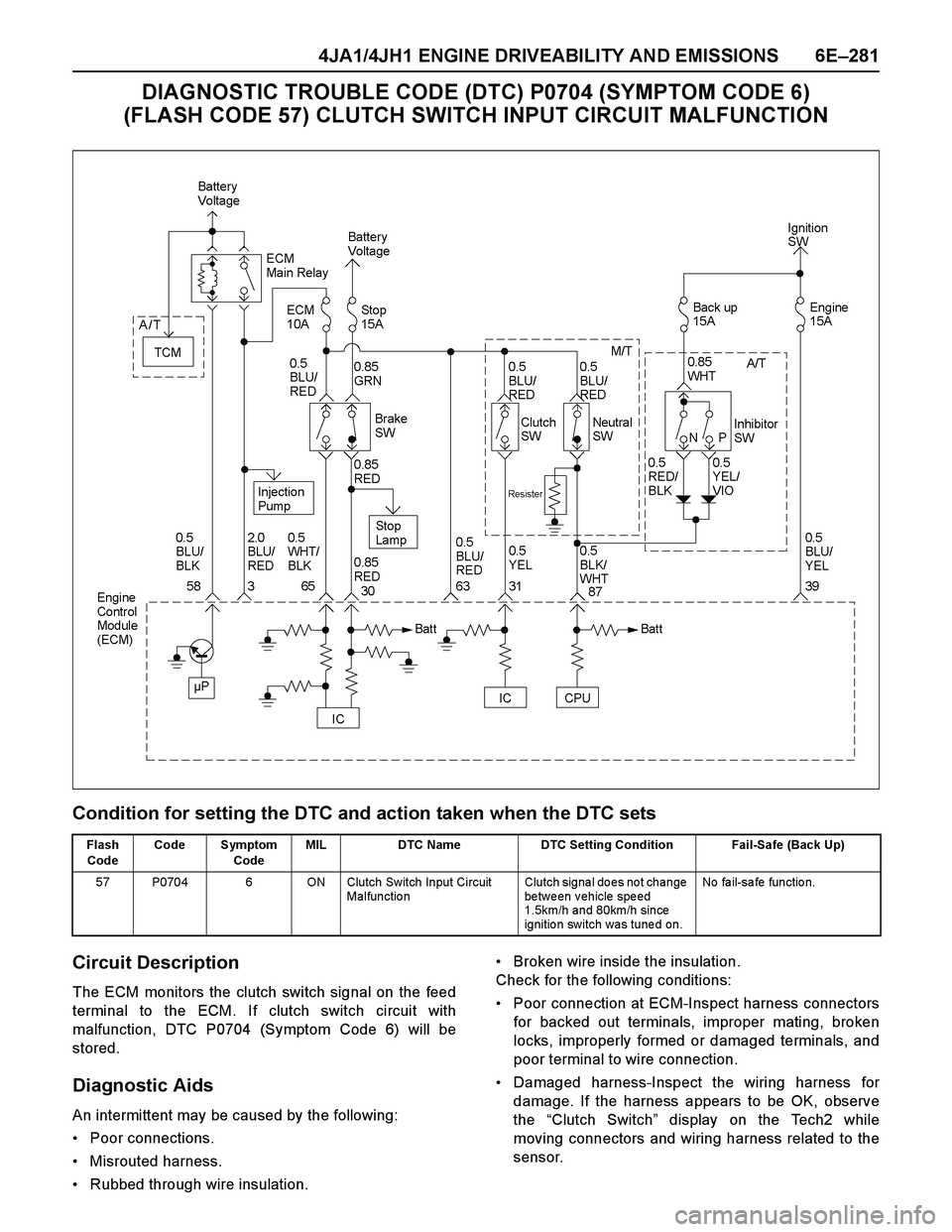
4JA1/4JH1 ENGINE DRIVEABILITY AND EMISSIONS 6E–281
DIAGNOSTIC TROUBLE CODE (DTC) P0704 (SYMPTOM CODE 6)
(FLASH CODE 57) CLUTCH SWITCH INPUT CIRCUIT MALFUNCTION
Condition for setting the DTC and action taken when the DTC sets
Circuit Description
The ECM monitors the clutch switch signal on the feed
terminal to the ECM. If clutch switch circuit with
malfunction, DTC P0704 (Symptom Code 6) will be
stored.
Diagnostic Aids
An intermittent may be caused by the following:
Poor connections.
Misrouted harness.
Rubbed through wire insulation.Broken wire inside the insulation.
Check for the following conditions:
Poor connection at ECM-Inspect harness connectors
for backed out terminals, improper mating, broken
locks, improperly formed or damaged terminals, and
poor terminal to wire connection.
Damaged harness-Inspect the wiring harness for
damage. If the harness appears to be OK, observe
the “Clutch Switch” display on the Tech2 while
moving connectors and wiring harness related to the
sensor.
Flash
CodeCode Symptom
CodeMIL DTC Name DTC Setting Condition Fail-Safe (Back Up)
57 P0704 6 ON Clutch Switch Input Circuit
Malfunctio nClutch signa l do es no t change
between vehicle speed
1.5km/h and 80km/h since
ignitio n switch was tune d on. No fa il-sa fe fun ctio n.
Page 1657 of 4264
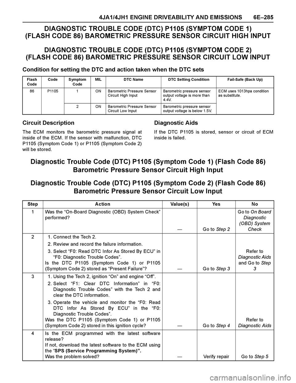
4JA1/4JH1 ENGINE DRIVEABILITY AND EMISSIONS 6E–285
DIAGNOSTIC TROUBLE CODE (DTC) P1105 (SYMPTOM CODE 1)
(FLASH CODE 86) BAROMETRIC PRESSURE SENSOR CIRCUIT HIGH INPUT
DIAGNOSTIC TROUBLE CODE (DTC) P1105 (SYMPTOM CODE 2)
(FLASH CODE 86) BAROMETRIC PRESSURE SENSOR CIRCUIT LOW INPUT
Condition for setting the DTC and action taken when the DTC sets
Circuit Description
The ECM monitors the barometric pressure signal at
inside of the ECM. If the sensor with malfunction, DTC
P1105 (Symptom Code 1) or P1105 (Symptom Code 2)
will be stored.
Diagnostic Aids
If the DTC P1105 is stored, sensor or circuit of ECM
inside is failed.
Diagnostic Trouble Code (DTC) P1105 (Sy mptom Code 1) (Flash Code 86)
Barometric Pressure Sensor Circuit High Input
Diagnostic Trouble Code (DTC) P1105 (Sy mptom Code 2) (Flash Code 86)
Barometric Pressure Sensor Circuit Low Input
Flash
CodeCode Symptom
CodeMIL DTC Name DTC Setting Condition Fail-Safe (Back Up)
86 P1105 1 ON Ba rome tric Pressure Se nsor
Circuit High InputBa rome tric pressure senso r
output voltage is more than
4.4V.ECM use s 1013hpa condition
as substitute .
2 ON Ba rome tric Pressure Se nsor
Circuit Lo w InputBa rome tric pressure senso r
output voltage is below 1.5V.
Step Action Value(s) Yes No
1Was the “On-Board Diagnostic (OBD) System Check”
performed?
—Go to Step 2Go to On Board
Diagnostic
(OBD) System
Check
2 1. Connect the Tech 2.
2. Review and record the failure information.
3. Select “F0: Read DTC Infor As Stored By ECU” in
“F0: Diagnostic Trouble Codes”.
Is the DTC P1105 (Symptom Code 1) or P1105
(Symptom Code 2) stored as “Present Failure”?—Go to Step 3Refer to
Diagnostic Aids
and Go to Step
3
3 1. Using the Tech 2, ignition “On” and engine “Off”.
2. Select “F1: Clear DTC Information” in “F0:
Diagnostic Trouble Codes” with the Tech 2 and
clear the DTC information.
3. Operate the vehicle and monitor the “F0: Read
DTC Infor As Stored By ECU” in the “F0:
Diagnostic Trouble Codes”.
Was the DTC P1105 (Symptom Code 1) or P1105
(Symptom Code 2) stored in this ignition cycle?—Go to Step 4Refer to
Diagnostic Aids
4 Is the ECM programmed with the latest software
release?
If not, download the latest software to the ECM using
the “SPS (Service Programming System)”.
Was the problem solved?—Verify repair Go to Step 5
Page 1659 of 4264
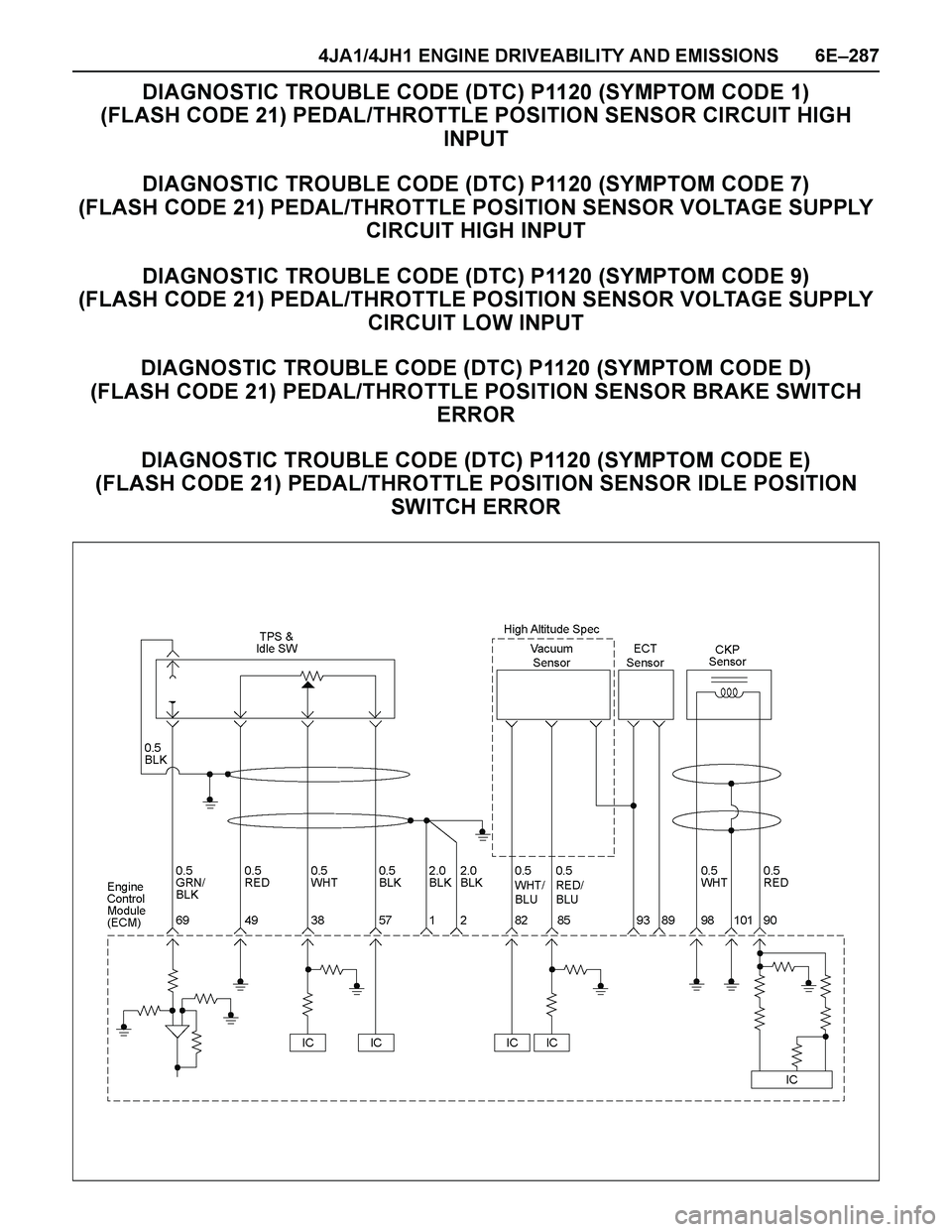
4JA1/4JH1 ENGINE DRIVEABILITY AND EMISSIONS 6E–287
DIAGNOSTIC TROUBLE CODE (DTC) P1120 (SYMPTOM CODE 1)
(FLASH CODE 21) PEDAL/THROTTLE POSITION SENSOR CIRCUIT HIGH
INPUT
DIAGNOSTIC TROUBLE CODE (DTC) P1120 (SYMPTOM CODE 7)
(FLASH CODE 21) PEDAL/THROTTLE POSITION SENSOR VOLTAGE SUPPLY
CIRCUIT HIGH INPUT
DIAGNOSTIC TROUBLE CODE (DTC) P1120 (SYMPTOM CODE 9)
(FLASH CODE 21) PEDAL/THROTTLE POSITION SENSOR VOLTAGE SUPPLY
CIRCUIT LOW INPUT
DIAGNOSTIC TROUBLE CODE (DTC) P1120 (SYMPTOM CODE D)
(FLASH CODE 21) PEDAL/THROTTLE POSITION SENSOR BRAKE SWITCH
ERROR
DIAGNOSTIC TROUBLE CODE (DTC) P1120 (SYMPTOM CODE E)
(FLASH CODE 21) PEDAL/THROTTLE POSITION SENSOR IDLE POSITION
SWITCH ERROR
Page 1660 of 4264
6E–288 4JA1/4JH1 ENGINE DRIVEABILITY AND EMISSIONS
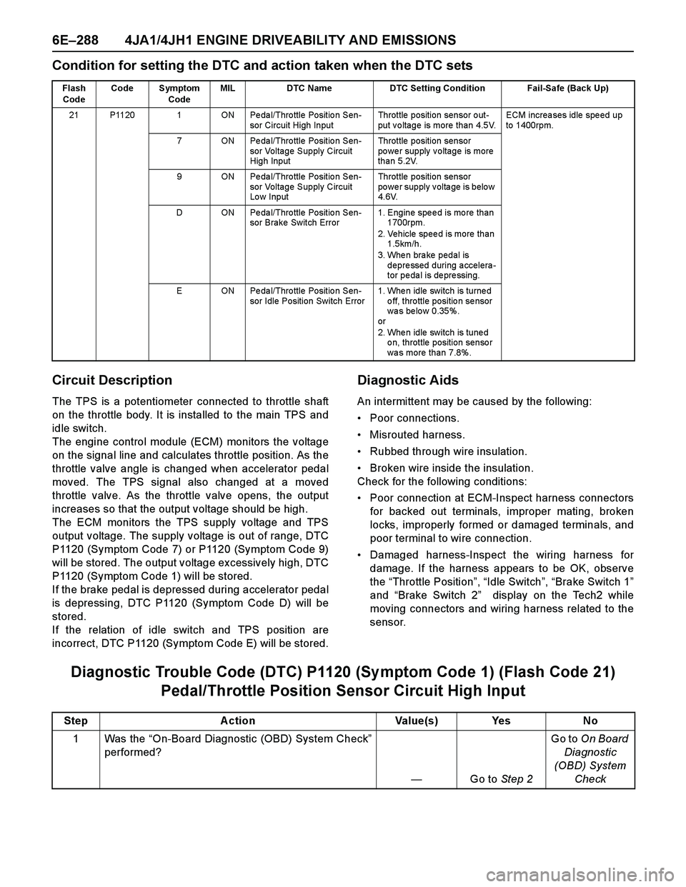
Condition for setting the DTC and action taken when the DTC sets
Circuit Description
The TPS is a potentiometer connected to throttle shaft
on the throttle body. It is installed to the main TPS and
idle switch.
The engine control module (ECM) monitors the voltage
on the signal line and calculates throttle position. As the
throttle valve angle is changed when accelerator pedal
moved. The TPS signal also changed at a moved
throttle valve. As the throttle valve opens, the output
increases so that the output voltage should be high.
The ECM monitors the TPS supply voltage and TPS
output voltage. The supply voltage is out of range, DTC
P1120 (Symptom Code 7) or P1120 (Symptom Code 9)
will be stored. The output voltage excessively high, DTC
P1120 (Symptom Code 1) will be stored.
If the brake pedal is depressed during accelerator pedal
is depressing, DTC P1120 (Symptom Code D) will be
stored.
If the relation of idle switch and TPS position are
incorrect, DTC P1120 (Symptom Code E) will be stored.
Diagnostic Aids
An intermittent may be caused by the following:
Poor connections.
Misrouted harness.
Rubbed through wire insulation.
Broken wire inside the insulation.
Check for the following conditions:
Poor connection at ECM-Inspect harness connectors
for backed out terminals, improper mating, broken
locks, improperly formed or damaged terminals, and
poor terminal to wire connection.
Damaged harness-Inspect the wiring harness for
damage. If the harness appears to be OK, observe
the “Throttle Position”, “Idle Switch”, “Brake Switch 1”
and “Brake Switch 2” display on the Tech2 while
moving connectors and wiring harness related to the
sensor.
Diagnostic Trouble Code (DTC) P1120 (Sy mptom Code 1) (Flash Code 21)
Pedal/Throttle Position Sensor Circuit High Input
Flash
CodeCode Symptom
CodeMIL DTC Name DTC Setting Condition Fail-Safe (Back Up)
21 P1120 1 ON Pedal/Throttle Position Sen-
sor Circuit High InputThrottle position sensor out-
put voltage is more than 4.5V.ECM increa ses idle spe ed up
to 1400rpm.
7 ON Pedal/Throttle Position Sen-
sor Voltage Supply Circuit
High InputThrottle position sensor
power supply voltage is more
than 5.2V.
9 ON Pedal/Throttle Position Sen-
sor Voltage Supply Circuit
Lo w InputThrottle position sensor
power supply voltage is below
4.6V.
D ON Pedal/Throttle Position Sen-
sor Brake Switch Error1. Engine speed is more than
1700rpm.
2. Vehicle speed is more than
1.5km/h.
3. When brake pedal is
depressed during accelera-
tor pe da l is de pre ssing.
E ON Pedal/Throttle Position Sen-
sor Idle Position Switch Error1. Whe n idle switch is turne d
o ff, thro ttle positio n se nsor
wa s be lo w 0.35%.
or
2. Whe n idle switch is tune d
on, throttle position sensor
was more than 7.8%.
Step Action Value(s) Yes No
1Was the “On-Board Diagnostic (OBD) System Check”
performed?
—Go to Step 2Go to On Board
Diagnostic
(OBD) System
Check
Page 1665 of 4264
4JA1/4JH1 ENGINE DRIVEABILITY AND EMISSIONS 6E–293
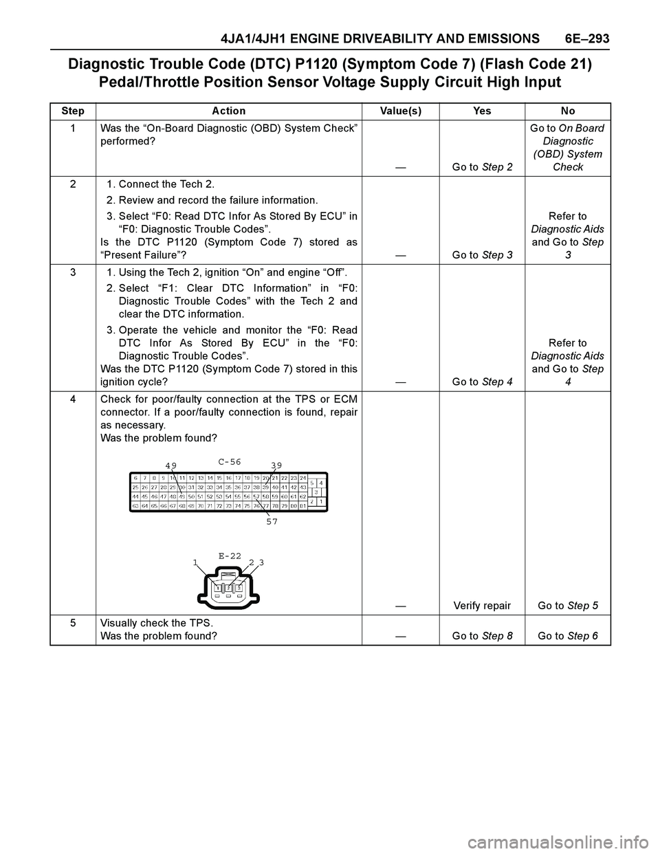
Diagnostic Trouble Code (DTC) P1120 (Sy mptom Code 7) (Flash Code 21)
Pedal/Throttle Position Sensor Voltage Supply Circuit High Input
Step Action Value(s) Yes No
1Was the “On-Board Diagnostic (OBD) System Check”
performed?
—Go to Step 2Go to On Board
Diagnostic
(OBD) System
Check
2 1. Connect the Tech 2.
2. Review and record the failure information.
3. Select “F0: Read DTC Infor As Stored By ECU” in
“F0: Diagnostic Trouble Codes”.
Is the DTC P1120 (Symptom Code 7) stored as
“Present Failure”?—Go to Step 3Refer to
Diagnostic Aids
and Go to Step
3
3 1. Using the Tech 2, ignition “On” and engine “Off”.
2. Select “F1: Clear DTC Information” in “F0:
Diagnostic Trouble Codes” with the Tech 2 and
clear the DTC information.
3. Operate the vehicle and monitor the “F0: Read
DTC Infor As Stored By ECU” in the “F0:
Diagnostic Trouble Codes”.
Was the DTC P1120 (Symptom Code 7) stored in this
ignition cycle?—Go to Step 4Refer to
Diagnostic Aids
and Go to Step
4
4 Check for poor/faulty connection at the TPS or ECM
connector. If a poor/faulty connection is found, repair
as necessary.
Was the problem found?
—Verify repair Go to Step 5
5 Visually check the TPS.
Was the problem found? —Go to Step 8Go to Step 6
4939
57
23 1C-56
E-22
Page 1667 of 4264
4JA1/4JH1 ENGINE DRIVEABILITY AND EMISSIONS 6E–295
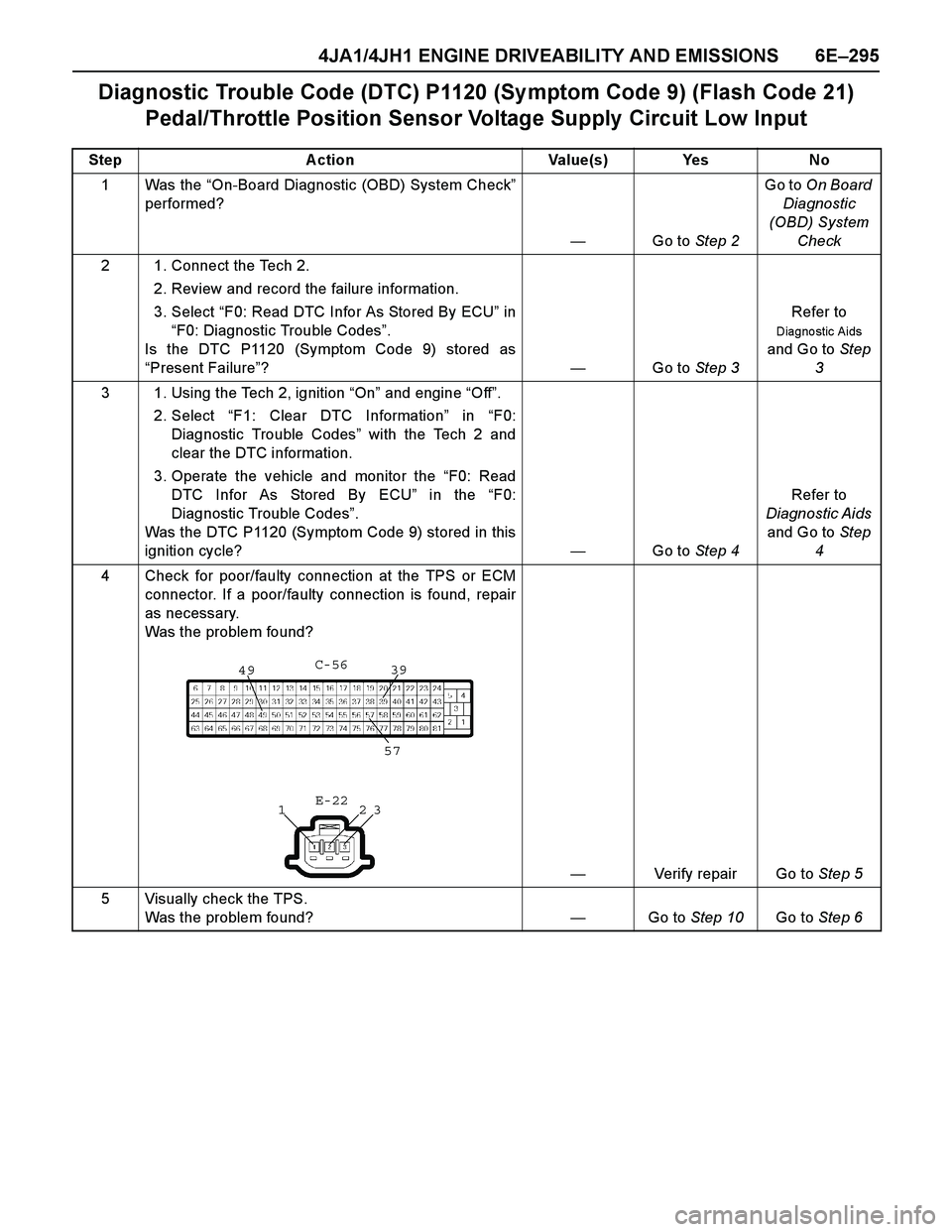
Diagnostic Trouble Code (DTC) P1120 (Sy mptom Code 9) (Flash Code 21)
Pedal/Throttle Position Sensor Voltage Supply Circuit Low Input
Step Action Value(s) Yes No
1Was the “On-Board Diagnostic (OBD) System Check”
performed?
—Go to Step 2Go to On Board
Diagnostic
(OBD) System
Check
2 1. Connect the Tech 2.
2. Review and record the failure information.
3. Select “F0: Read DTC Infor As Stored By ECU” in
“F0: Diagnostic Trouble Codes”.
Is the DTC P1120 (Symptom Code 9) stored as
“Present Failure”?—Go to Step 3Refer to
Diagno stic Aids
and Go to Step
3
3 1. Using the Tech 2, ignition “On” and engine “Off”.
2. Select “F1: Clear DTC Information” in “F0:
Diagnostic Trouble Codes” with the Tech 2 and
clear the DTC information.
3. Operate the vehicle and monitor the “F0: Read
DTC Infor As Stored By ECU” in the “F0:
Diagnostic Trouble Codes”.
Was the DTC P1120 (Symptom Code 9) stored in this
ignition cycle?—Go to Step 4Refer to
Diagnostic Aids
and Go to Step
4
4 Check for poor/faulty connection at the TPS or ECM
connector. If a poor/faulty connection is found, repair
as necessary.
Was the problem found?
—Verify repair Go to Step 5
5 Visually check the TPS.
Was the problem found? —Go to Step 10Go to Step 6
4939
57
23 1C-56
E-22