Page 3980 of 4264

7A1-34 CONSTRUCTION AND FUNCTION
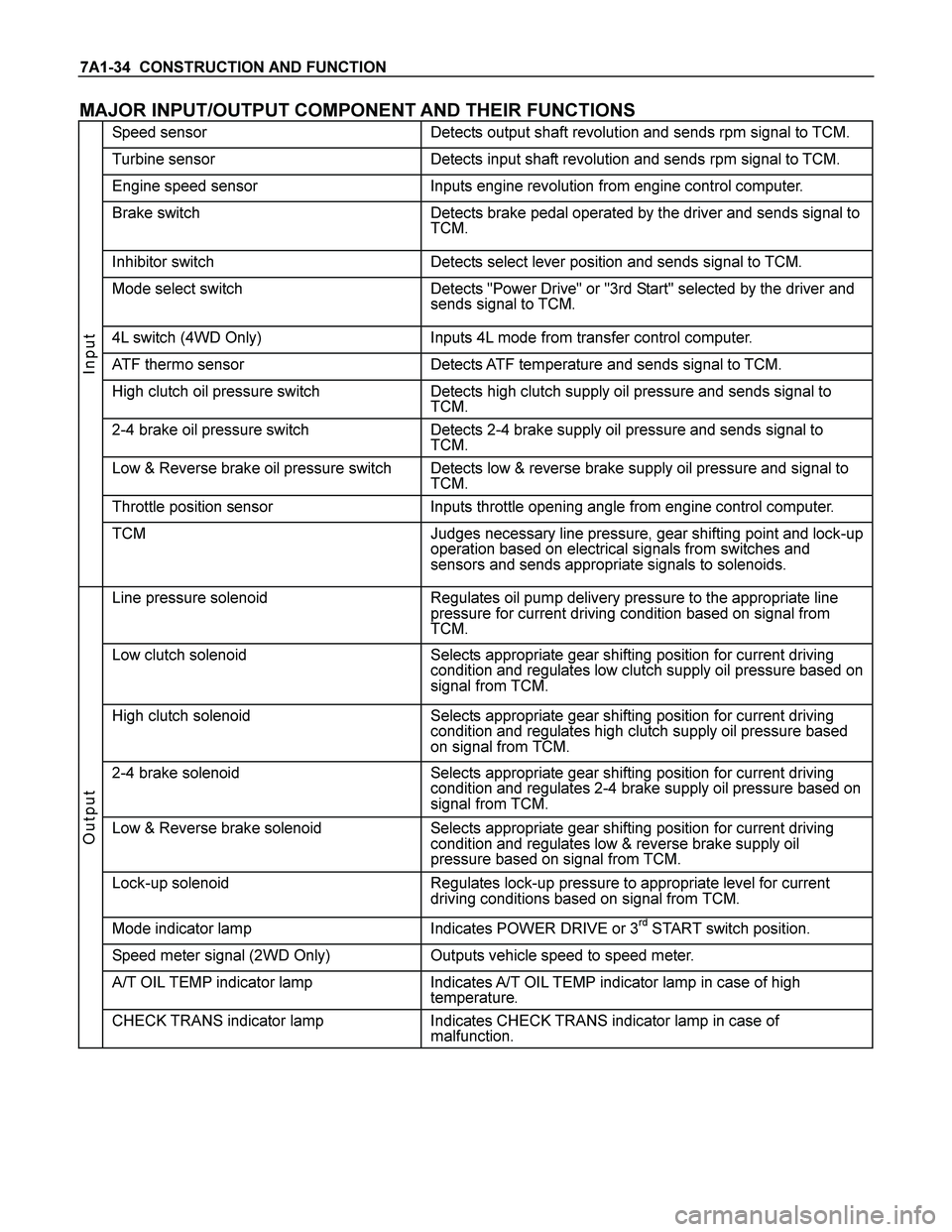
MAJOR INPUT/OUTPUT COMPONENT AND THEIR FUNCTIONS
Speed sensor Detects output shaft revolution and sends rpm signal to TCM.
Turbine sensor Detects input shaft revolution and sends rpm signal to TCM.
Engine speed sensor Inputs engine revolution from engine control computer.
Brake switch Detects brake pedal operated by the driver and sends signal to
TCM.
Inhibitor switch Detects select lever position and sends signal to TCM.
Mode select switch Detects "Power Drive" or "3rd Start" selected by the driver and
sends signal to TCM.
4L switch (4WD Only) Inputs 4L mode from transfer control computer.
ATF thermo sensor Detects ATF temperature and sends signal to TCM.
High clutch oil pressure switch Detects high clutch supply oil pressure and sends signal to
TCM.
2-4 brake oil pressure switch Detects 2-4 brake supply oil pressure and sends signal to
TCM.
Low & Reverse brake oil pressure switch Detects low & reverse brake supply oil pressure and signal to
TCM.
Throttle position sensor Inputs throttle opening angle from engine control computer.
Input
TCM Judges necessary line pressure, gear shifting point and lock-up
operation based on electrical signals from switches and
sensors and sends appropriate signals to solenoids.
Line pressure solenoid Regulates oil pump delivery pressure to the appropriate line
pressure for current driving condition based on signal from
TCM.
Low clutch solenoid Selects appropriate gear shifting position for current driving
condition and regulates low clutch supply oil pressure based on
signal from TCM.
High clutch solenoid Selects appropriate gear shifting position for current driving
condition and regulates high clutch supply oil pressure based
on signal from TCM.
2-4 brake solenoid Selects appropriate gear shifting position for current driving
condition and regulates 2-4 brake supply oil pressure based on
signal from TCM.
Low & Reverse brake solenoid Selects appropriate gear shifting position for current driving
condition and regulates low & reverse brake supply oil
pressure based on signal from TCM.
Lock-up solenoid Regulates lock-up pressure to appropriate level for current
driving conditions based on signal from TCM.
Mode indicator lamp Indicates POWER DRIVE or 3rd START switch position.
Speed meter signal (2WD Only) Outputs vehicle speed to speed meter.
A/T OIL TEMP indicator lamp Indicates A/T OIL TEMP indicator lamp in case of high
temperature.
Output
CHECK TRANS indicator lamp Indicates CHECK TRANS indicator lamp in case of
malfunction.
Page 3981 of 4264
CONSTRUCTION AND FUNCTION 7A1-35
CONTROL CIRCUIT BLOCK DIAGRAM
Speed sensor
Turbine sensor
Brake switch
Inhibitor switch
Power drive, 3rd start
switch
ATF oil thermo sensor
High clutch oil pressure
switch
2-4 brake oil pressure
switch
Low & reverse brake oil
pressure switch
Transfer control module
(4WD Only)
Engine Control Module
(ECM)
Line pressure solenoid
Low clutch solenoid
High clutch solenoid
2-4 brake solenoid
Low & reverse brake
solenoid
Lock-up solenoid
ATF temperature
indicator lamp
Speed meter (2WD
Only)
Power, 3rd start indicator
lamp
Check trans indicator
lamp
Data link connector Self-diagnosis
function
Transmission
Control
Module
(TCM)
4L mode
Engine
speed
Throttle
angle
Figure 54. Control Circuit Block Diagram
Page 3983 of 4264
CONSTRUCTION AND FUNCTION 7A1-37
COMPONENT AND THEIR OPERATING CONDITION
Clutch Brake Solenoid Pressure Switch
Select
lever
position
Gear
position
Gear
Shift
Lock-
up
L/C
H/C
R/C
L/O.C
L&R/B
2-4/B
L/C.S
H/C.S
L&R/
B.S
2-4/
B.S
L/U.S H/
C.P/
SWL&R/
B.P/
SW2-4
B.P/
SW
P - -
R Reverse -
N - -
1st
2nd
3rd
D
4th
1st
2nd
3rd
3
4th(*1)
1st
2nd
3rd(*1)
2
4th(*1)
1st
2nd(*1)
3rd(*1)
L
4th(*1)
*1:Transmission is shifted at high speed to prevent engine over-run.
- Engaged or operated
- Operative when accelerating
Page 3987 of 4264

CONSTRUCTION AND FUNCTION 7A1-41
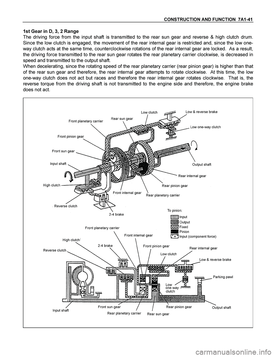
1st Gear in D, 3, 2 Range
The driving force from the input shaft is transmitted to the rear sun gear and reverse & high clutch drum.
Since the low clutch is engaged, the movement of the rear internal gear is restricted and, since the low one-
way clutch acts at the same time, counterclockwise rotations of the rear internal gear are locked. As a result,
the driving force transmitted to the rear sun gear rotates the rear planetary carrier clockwise, is decreased in
speed and transmitted to the output shaft.
When decelerating, since the rotating speed of the rear planetary carrier (rear pinion gear) is higher than that
of the rear sun gear and therefore, the rear internal gear attempts to rotate clockwise. At this time, the low
one-way clutch does not act but races and therefore the rear internal gear rotates clockwise. That is, the
reverse torque from the driving shaft is not transmitted to the engine side and therefore, the engine brake
does not act.
Page 3988 of 4264
7A1-42 CONSTRUCTION AND FUNCTION
1st Gear in L Range
The basic mechanism is the same as in the D, 3, and 2 Range. To apply the engine brake, the low & reverse
brake is engaged to restrict the movement of the low one-way clutch.
When decelerating, since the rear internal gear is fixed, reverse torque from the drive shaft is transmitted to
the engine side so that the engine brake is applied.
Page 3989 of 4264
CONSTRUCTION AND FUNCTION 7A1-43
2nd Gear in D, 3, 2 Range
The driving force from the input shaft is transmitted to the rear sun gear and reverse & high clutch drum. As
in the case of the 1st gear, since the low clutch is engaged, the movement of the rear internal gear is
restricted. Since the 2-4 brake is engaged, the front sun gear is fixed. As a result, movement of the rear
internal gear is restricted, and the driving force transmitted to the rear sun gear rotates the rear planetary
carrier clockwise, and is decreased and output. The rotating speed of the rear planetary carrier is increased
as the rear internal gear rotates.
When decelerating, the engine brake is applied.
Page 3990 of 4264
7A1-44 CONSTRUCTION AND FUNCTION
3rd Gear in D, 3 Range
The driving force from the input shaft is transmitted to the rear sun gear and reverse & high clutch drum. As
in the case of the 1st gear and 2nd gear, since the low clutch is engaged, the movement of the rear internal
gear is restricted. Since the high clutch is engaged, the driving force from the input shaft is directly
transmitted to the rear internal gear. As a result, the rpm of the rear sun gear and the rear internal gear
becomes the same as that of the input shaft so that the rear pinion gear rotates not independently but
together with the rear sun gear and rear internal gear.
When decelerating, the engine brake is applied.
Page 3993 of 4264

DIAGNOSIS (JR405E) 7A2-1
SECTION 7A2
DIAGNOSIS
TABLE OF CONTENTS
PAGE
BASIC TROUBLE SHOOTING..................................................................................................7A2-6
CHECK TRANS INDICATOR & SELF DIAGNOSIS..............................................................7A2-7
DIAGNOSIS WITH TECH 2........................................................................................................7A2-9
TECH 2 CONNECTION .................................................................................................. 7A2-9
TECH 2 OPERATING FLOW CHART (START UP)..............................................................7A2-10
TYPICAL SCAN DATA................................................................................................................7A2-13
MISCELLANEOUS TEST...........................................................................................................7A2-14
INTERMITTENT DIAGNOSIS....................................................................................................7A2-16
SNAPSHOT DISPLAY WITH TIS 2000....................................................................................7A2-17
SERVICE PROGRAMMING SYSTEM (SPS) ................................................................. 7A2-21
CIRCUIT DIAGRAM.....................................................................................................................7A2-24
PART LOCATION........................................................................................................................7A2-26
CONNECTOR LIST.....................................................................................................................7A2-31
DIAGNOSIS TROUBLE CODE TABLE...................................................................................7A2-33
FAIL-SAFE FUNCTION..............................................................................................................7A2-35
DTC P0722 (FLASH CODE 11) VEHICLE SPEED SENSOR NO SIGNAL......................7A2-36
DTC P0727 (FLASH CODE 13) ENGINE REVOLUTION SENSOR NO SIGNAL............7A2-38
DTC P0717 (FLASH CODE 14) TURBINE SPEED SENSOR NO SIGNAL......................7A2-40
DTC P0710 (FLASH CODE 15) ATF TEMPERATURE SENSOR FAILURE....................7A2-42
DTC P0560 (FLASH CODE 16) SYSTEM VOLTAGE FAILURE........................................7A2-43
DTC P0705 (FLASH CODE 17) INHIBITOR SWITCH FAILURE........................................7A2-44
DTC P1120 (FLASH CODE 22) THROTTLE SIGNAL FAILURE........................................7A2-46
DTC P1875 (FLASH CODE 25) GND RETURN CIRCUIT FAILURE.................................7A2-47
DTC P0753 (FLASH CODE 31) LOW & REVERSE BRAKE DUTY
SOLENOID FAILURE................................................................................................................7A2-48
DTC P0758 (FLASH CODE 32) 2-4 BRAKE DUTY SOLENOID FAILURE......................7A2-51
DTC P0763 (FLASH CODE 33) HIGH CLUTCH DUTY SOLENOID FAILURE................7A2-54
DTC P0768 (FLASH CODE 34) LOW CLUTCH DUTY SOLENOID FAILURE................7A2-57