Page 3774 of 4264
7A3-18 ON-VEHICLE SERVICE (AW30 –40LE)
“ L" Range Test
1. While running above 80 km/h (50 mph) in the “D"
range, release your foot from the accelerator pedal
and shift into the “L" range.
Then check to see that the 2 �
1 downshift occurs at
the specified point shown on the automatic shift
diagram.
RUW37ASH000601
2. While running in the “L" range, check to see that
there is no upshift to 2nd gear.
3. While running in the “L" range, release the
accelerator pedal and check the engine braking
effect.
4. Check for abnormal noise during acceleration and deceleration.
RUW37ASH000701
“ R" Range Test
Shift into the “R" range and, while starting at full throttle,
check for slipping.
RUW37ASH000801
“ P" Range Test
Stop the vehicle on a grade (more than 9%) and afte
r
shifting into the “P" range, release the parking brake.
Then check to see that the parking lock pawl holds the
vehicle in place.
Page 3777 of 4264
ON-VEHICLE SERVICE (AW30 –40LE) 7A3-21
Transmission Fluid Level and Condition
Inspection
Park vehicle on level ground and set parking brake.
With the engine idling, move the shift lever through all
positions from “P" to “L", then return to position “P".
Check to see if the level of fluid comes to “HOT" range
of about 80 �
� �
�
C (176 �
� �
�
F) on the dipstick gauge.
If the level of fluid is too low, replenish to bring it to
maximum level in “HOT" range.
Inspection of fluid condition. If the ATF is black o
r
smells burnt, replace it.
RUW37ASH002501
Page 3778 of 4264
7A3-22 ON-VEHICLE SERVICE (AW30 –40LE)
ATF Replacement
Inspection
NOTE: Do not overfill.
1. Remove the drain plug from oil pan and drain the
fluid.
RUW17ASH013401
2. Reinstall the drain plug securely.
Torque: 19 N �
��
�
m (14 Ib ft)
3. With the engine OFF, add new fluid through the fille
r
tube.
Drain and refill 5.2 liter
Dry fill 8.7 liter
Fluid BESCO ATF III
4. Start the engine and shift the selector into all
position from “P" through “L", and then shift into “P".
5. With the engine idling, check the fluid level. Add fluid up to the “COLD" level on the dipstick.
6. The ATF level must be checked again for correct level with the “HOT" level.
NOTE: To prevent fluid leaks, the drain plug gasket
must be replaced each time this plug is removed.
Page 3779 of 4264
 7A3-23
Neutral Start Switch (Mode Switch)
Inspection
With a circuit tester, make a continuity test on the
neutral start switch with the moving piece set in e")
ON-VEHICLE SERVICE (AW30 –40LE) 7A3-23
Neutral Start Switch (Mode Switch)
Inspection
With a circuit tester, make a continuity test on the
neutral start switch with the moving piece set in each
position.
RTW37BSH000101
Removal
Preparation:
Disconnect negative ( –) battery cable.
1. Remove the rear side ATF cooler pipe from the
transmission elbow.
2. Disconnect neutral start switch connector.
3. Unstake the lock washer, and then remove the shaft
nut.
4. Remove the neutral start switch.
Installation
To install, follow the removal steps in the reverse order,
noting the following points;
If a engine starts at any selector position except “N ” o
r
“ P ”, the neutral start switch (mode switch) should be
adjusted.
1. Loosen the neutral start switch bolt and set the shift
selector to the “N" range.
2. Align the groove and neutral basic line.
3. Hold in position and tighten the bolt and nut.
Torque:
Nut – 7 N �
��
�
m (61 Ib in)
Bolt – 13 N �
��
�
m (113 Ib in)
4. Lock the nut with the lock washer tubs at two points.
RUW17ASH013601
Page 3791 of 4264
 7A3-35
Shift Solenoid and Lock-Up Solenoid
Removal
Preparation:
Disconnect negative ( –) battery cable.
Drain the fluid.
Refer to ATF REPL")
ON-VEHICLE SERVICE (AW30 –40LE) 7A3-35
Shift Solenoid and Lock-Up Solenoid
Removal
Preparation:
Disconnect negative ( –) battery cable.
Drain the fluid.
Refer to ATF REPLACEMENT in this section.
1. Remove oil lever gage and oil filler tube.
2. Support transfer case (4
�4) or rear cover (4�2)
with a transmission jack.
3. Remove engine rear mounting nuts.
F07RW008
4. Remove fule pipe heat protector on tansmission
corssmenber.
5. Remove fuel pipe from the crossmenber.
6. Remove transmission crossmenber.
7. Remove the nineteen bolts.
8. Remove oil pan, using seal cutter J –37228.
RUW37ASH002901
NOTE: Do not turn over the transmission as this will
contaminate the valve body with foreign materials in the
bottom of the oil pan.
Remove oil pan by lifting the transmission case.
Oil pan seal cutter: J –37228
Examine particles in oil pan
Remove the magnet and use it to collect any steel
chips.
Look carefully at the chips and particles in the oil
pan and on the magnet to anticipate what type o
f
wear you will find in the transmission:
Steel (magnetic) ..................bearing, gear and
clutch plate wear
Brass (non-magnetic) ..........bushing wear
240RY00008
9. Remove the oil strainer assembly.
244RY00003
Page 3801 of 4264
ON-VEHICLE SERVICE (AW30 –40LE) 7A3-45
19.Support the transmission with a transmission jack.
220RS0001
20.Remove the transmission crossmember.
Remove engine rear mount nuts fixing on
transmission crossmember.
P1010018
Remove the transmission crossmember by
removing four fixing bolts.
If necessary, remove the rear mount rubber from
the transmission.
21. Disconnect the air bleezer hose at the transmission.
22.Remove the protector and fuel pipe bracket.
Loosen the nut (1) and remove the protector (2).
Remove the bracket with the fuel pipes (3) and
put aside it.
RTW37ASH001201
23.Remove the transmission assembly.
Remove transmission retaining nuts and bolts.
Remove transmission assembly from the vehicle.
Page 3802 of 4264
7A3-46 ON-VEHICLE SERVICE (AW30 –40LE)
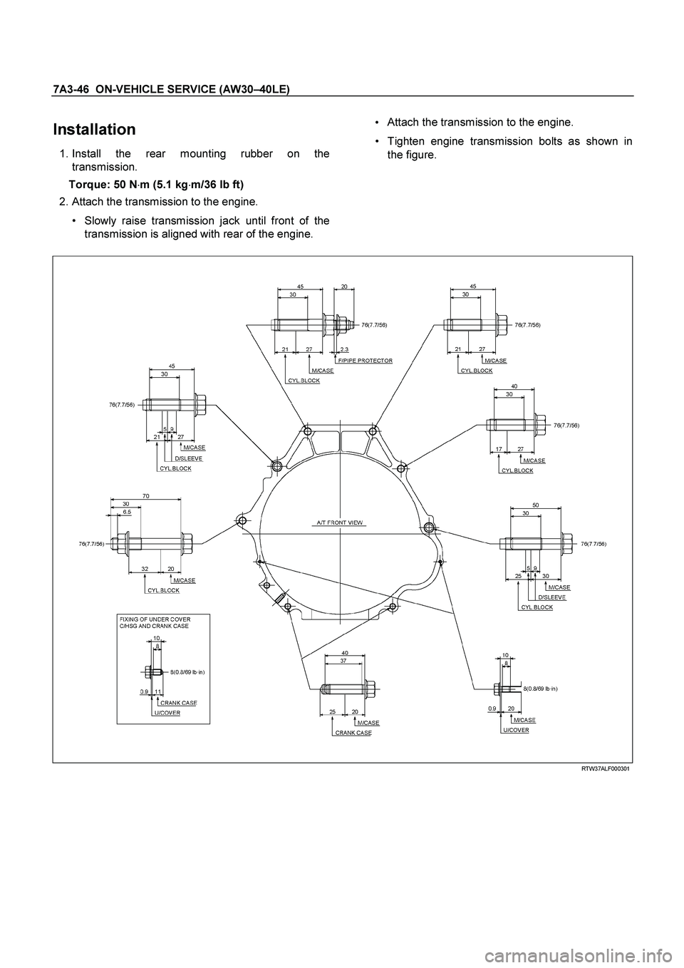
Installation
1. Install the rear mounting rubber on the
transmission.
Torque: 50 N �m (5.1 kg �m/36 lb ft)
2. Attach the transmission to the engine.
Slowly raise transmission jack until front of the
transmission is aligned with rear of the engine.
Attach the transmission to the engine.
Tighten engine transmission bolts as shown in
the figure.
RTW37ALF000301
Page 3803 of 4264
 7A3-47
3. Install the protector and fuel pipe bracket.
Install the bracket with the fuel pipes (3) to the
transmission.
Install the protector (2)")
ON-VEHICLE SERVICE (AW30 –40LE) 7A3-47
3. Install the protector and fuel pipe bracket.
Install the bracket with the fuel pipes (3) to the
transmission.
Install the protector (2) and tighten nuts (1).
RTW37ASH001201
4. Connect the air bleezer hose on the transmission.
5. Install the transmission crossmember.
Torque: 67 N �
��
�
m (6.8 kg �
��
�
m/49 lb ft)
6. Install the heat protector and the fuel pipe clips with
fuel pipes on the transmission crossmember.
P1010005B
7. Install rear mount nuts.
Torque: 50 N �
��
�
m (5.3 kg
�
��
�
m/37 lb ft)
8. Remove a transmission jack.
9. Install flex plate torque converter bolts.
Align the flex plate torque converter bolt boss
with flex plate hole by turning the torque
converter.
Install flex plate torque converter bolts (6 pieces)
by turning the crankshaft.
Torque: 54 N �
��
�
m (54 kg
�
��
�
m/40 lb ft)
NOTE: Do not reuse the flex plate torque converte
r
bolt.
P1010005
10.Install the under covers to the transmission and
engine.
Torque: 8 N �
��
�
m (0.8 kg
�
��
�
m/69 lb in)
P1010012

“ L\" Range Test
1. While running above 80 km/h (50 mph) in the “D\"
range, release your foot from the accelerator pedal
and shift into the �")
 7A3-21
Transmission Fluid Level and Condition
Inspection
Park vehicle on level ground and set parking brake.
With the engine idling, move the shift lever thr")

ATF Replacement
Inspection
NOTE: Do not overfill.
1. Remove the drain plug from oil pan and drain the
fluid.
RUW17ASH013401
2. Re")
 7A3-45
19.Support the transmission with a transmission jack.
220RS0001
20.Remove the transmission crossmember.
Remove engine rear mount nuts fixin")