Page 2440 of 4264
6A-20 ENGINE MECHANICAL (C24SE)
6. Install power steering pump and V-belt.
Adjust
Adjust power steering pump V-belt tension according to the
corresponding operation.
Installation
7. Install radiator according to the corresponding operation.
8. Install air inlet hose.
9. Install all electrical cable connections, hoses and lines to
engine.
10. Install accelerator cable from inlet pipe.
11. Install bonnet.
Inspection
1. Check engine oil level.
2. Fill up cooling system and bleed according to the
corresponding operation.
Page 2441 of 4264
ENGINE MECHANICAL (C24SE) 6A-21
Toothed Belt and Timing Check
Removal
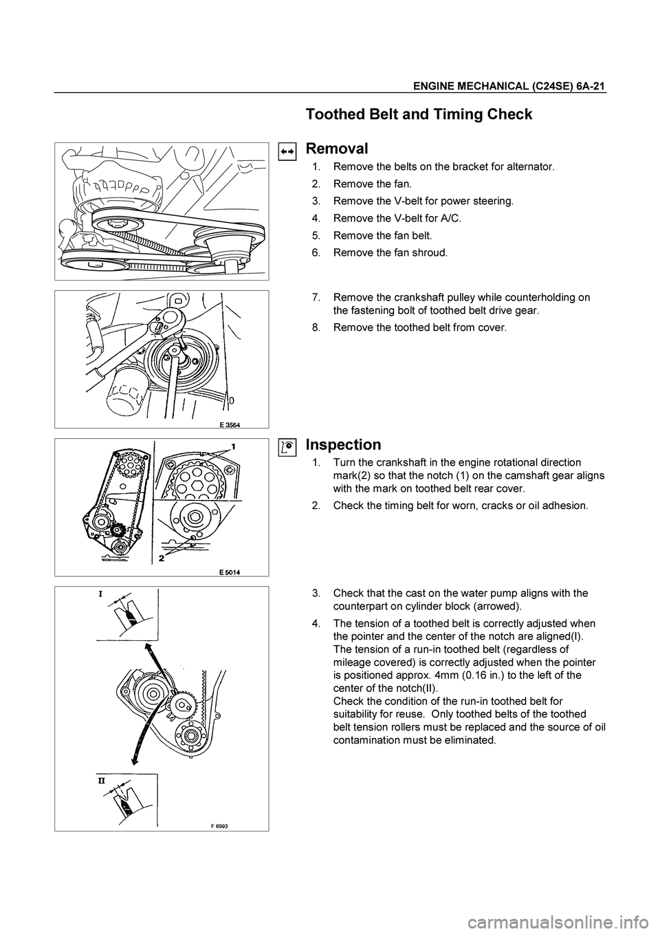
1. Remove the belts on the bracket for alternator.
2. Remove the fan.
3. Remove the V-belt for power steering.
4. Remove the V-belt for A/C.
5. Remove the fan belt.
6. Remove the fan shroud.
7. Remove the crankshaft pulley while counterholding on
the fastening bolt of toothed belt drive gear.
8. Remove the toothed belt from cover.
Inspection
1. Turn the crankshaft in the engine rotational direction
mark(2) so that the notch (1) on the camshaft gear aligns
with the mark on toothed belt rear cover.
2. Check the timing belt for worn, cracks or oil adhesion.
3. Check that the cast on the water pump aligns with the
counterpart on cylinder block (arrowed).
4. The tension of a toothed belt is correctly adjusted when
the pointer and the center of the notch are aligned(I).
The tension of a run-in toothed belt (regardless of
mileage covered) is correctly adjusted when the pointer
is positioned approx. 4mm (0.16 in.) to the left of the
center of the notch(II).
Check the condition of the run-in toothed belt for
suitability for reuse. Only toothed belts of the toothed
belt tension rollers must be replaced and the source of oil
contamination must be eliminated.
Page 2453 of 4264
ENGINE MECHANICAL (C24SE) 6A-33
HYDRAULIC VALVE LIFTER
1. Hydraulic Valve Lifter
1. Oil reservoir
2. Piston with ball head (moving)
3. Pressure cylinder (fixed)
4. Check ball
5. Pressure chamber
6. Oil feed
Page 2470 of 4264
6A-50 ENGINE MECHANICAL (C24SE)
Clean
Sealing surfaces.
013RW004
Installation
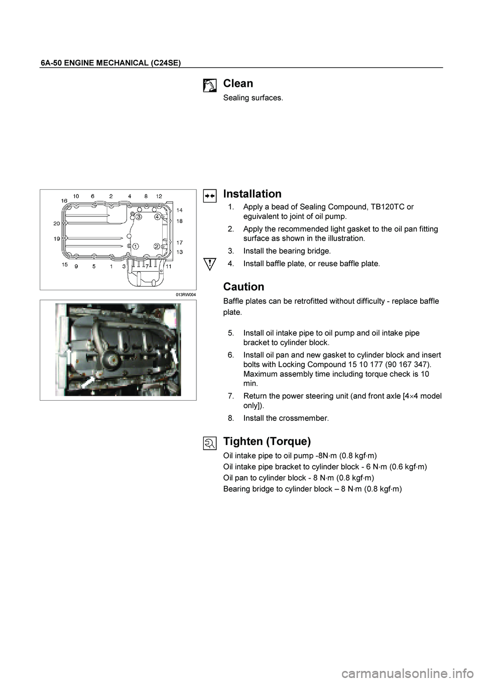
1. Apply a bead of Sealing Compound, TB120TC or eguivalent to joint of oil pump.
2. Apply the recommended light gasket to the oil pan fitting surface as shown in the illustration.
3. Install the bearing bridge.
4. Install baffle plate, or reuse baffle plate.
Caution
Baffle plates can be retrofitted without difficulty - replace baffle
plate.
5. Install oil intake pipe to oil pump and oil intake pipe bracket to cylinder block.
6. Install oil pan and new gasket to cylinder block and insert bolts with Locking Compound 15 10 177 (90 167 347).
Maximum assembly time including torque check is 10
min.
7. Return the power steering unit (and front axle [4 �
4 model
only]).
8. Install the crossmember.
Tighten (Torque)
Oil intake pipe to oil pump -8N �
m (0.8 kgf �
m)
Oil intake pipe bracket to cylinder block - 6 N �
m (0.6 kgf �
m)
Oil pan to cylinder block - 8 N �
m (0.8 kgf �
m)
Bearing bridge to cylinder block – 8 N �
m (0.8 kgf �
m)
Page 2477 of 4264
ENGINE MECHANICAL (C24SE) 6A-57
Inspection
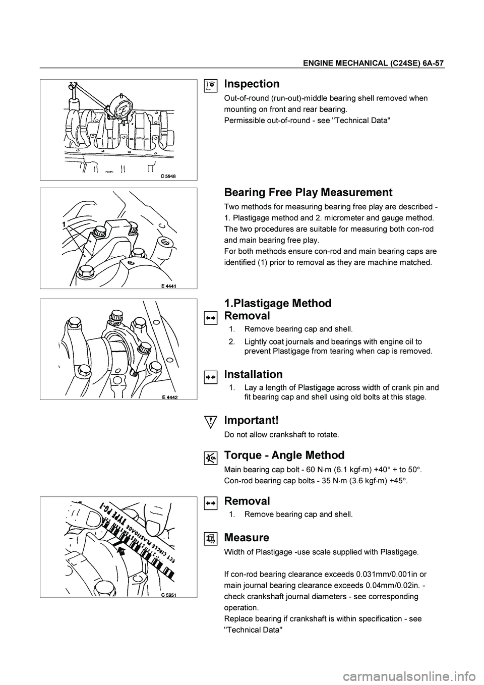
Out-of-round (run-out)-middle bearing shell removed when
mounting on front and rear bearing.
Permissible out-of-round - see "Technical Data"
Bearing Free Play Measurement
Two methods for measuring bearing free play are described -
1. Plastigage method and 2. micrometer and gauge method.
The two procedures are suitable for measuring both con-rod
and main bearing free play.
For both methods ensure con-rod and main bearing caps are
identified (1) prior to removal as they are machine matched.
1.Plastigage Method
Removal
1. Remove bearing cap and shell.
2. Lightly coat journals and bearings with engine oil to
prevent Plastigage from tearing when cap is removed.
Installation
1. Lay a length of Plastigage across width of crank pin and
fit bearing cap and shell using old bolts at this stage.
Important!
Do not allow crankshaft to rotate.
Torque - Angle Method
Main bearing cap bolt - 60 N�
m (6.1 kgf�
m) +40�
+ to 50�
.
Con-rod bearing cap bolts - 35 N�
m (3.6 kgf�
m) +45�
.
Removal
1. Remove bearing cap and shell.
Measure
Width of Plastigage -use scale supplied with Plastigage.
If con-rod bearing clearance exceeds 0.031mm/0.001in or
main journal bearing clearance exceeds 0.04mm/0.02in. -
check crankshaft journal diameters - see corresponding
operation.
Replace bearing if crankshaft is within specification - see
"Technical Data"
Page 2480 of 4264
6A-60 ENGINE MECHANICAL (C24SE)
Oil Pump Safety Valve
Removal
1. Remove closure plug.
2. Remove seal ring.
3. Remove spring.
4. Remove piston.
Installation
1. Install piston (observe installation position).
2. Install spring.
3. Install seal ring.
4. Install closure plug.
Tighten (Torque)
Closure plug - 30 N�
m (3.0 kgf�
m)
Oil Pump (Overhaul)
Removal
1. Remove oil pump according to the corresponding
operation.
2. Remove oil cover and pressure control valve.
Inspect
Clearance between gear pair and housing upper edge - see
“Technical Data”.
Check housing, cover and pressure control valve.
Installation
1. Install pump cover with Sealing Compound 15 03 166 (90
094 714).
2. Install oil pump safety valve according to the
corresponding operation.
3. Install oil pump according to the corresponding operation.
Page 2516 of 4264
6B-6 ENGINE COOLING
Draining and Refilling Cooling
System
Before draining the cooling system, inspect the system and
perform any necessary service to ensure that it is clean, does
not leak and is in proper working order. The engine coolant
(EC) level should be between the "MIN" and "MAX" lines of
reserve tank when the engine is cold. If low, check for leakage
and add EC up to the "MAX" line. There should not be any
excessive deposit of rust or scales around the radiator cap or
radiator filler hole, and the EC should also be free from oil.
Replace the EC if excessively dirty.
1. Completely drain the cooling system by opening the drain
plug at the bottom of the radiator.
2. Remove the radiator cap.
WARNING: TO AVOID THE DANGER OF BEING BURNED,
DO NOT REMOVE THE CAP WHILE THE ENGINE AND
RADIATOR ARE STILL HOT. SCALDING FLUID AND
STEAM CAN BE BLOWN OUT UNDER PRESSURE.
3. Disconnect all hoses from the EC reserve tank.
Scrub and clean the inside of the reserve tank with soap
and water. Flush it well with clean water, then drain it. Install
the reserve tank and hoses.
4. Refill the cooling system with the EC using a solution that is
at least 50 percent antifreeze.
5. Fill the radiator to the base of the filler neck.
Fill the EC reserve tank to "MAX" line when the engine is
cold.
6. Block the drive wheels and firmly apply the parking brake.
Shift an automatic transmission to "P" (Park) or a manual
transmission to neutral.
7. Remove the radiator cap. Start the engine and warm it up a
t
2,500 - 3,000 rpm for about 30 minutes.
8. When the air comes out from the radiator filler neck and the
EC level has gone down, replenish with the EC. Repeat this
procedure until the EC level does not go down. Then stop
the engine and install the radiator cap. Let the engine cool
down.
9. After the engine has cooled, replenish with EC up to the
"MAX" line of the reserve tank.
10. Start the engine. With the engine running at 3,000 rpm,
make sure there is no running water sound from the heate
r
core (behind the center console).
11. If the running water sound is heard, repeat steps 8 to 10.
Page 2527 of 4264
ENGINE FUEL (C24SE) 6C-3
When working on the fuel system, there are several things to
keep in mind:
�
Any time the fuel system is being worked on, disconnect the
negative battery cable except for those tests where battery
voltage is required.
�
Always keep a dry chemical (Class B) fire extinguisher near
the work area.
� Replace all pipes with the same pipe and fittings that were
removed.
� Clean and inspect "O" rings. Replace if required.
�
Always relieve the line pressure before servicing any fuel
system components.
� Do not attempt repairs on the fuel system until you have
read the instructions and checked the pictures relating to
that repair.
� Adhere to all Notices and Cautions.
All gasoline engines are designed to use only unleaded
gasoline. Unleaded gasoline must be used for proper emission
control system operation.
Its use will also minimize spark plug fouling and extend engine
oil life. Using leaded gasoline can damage the emission control
system and could result in loss of emission warranty coverage.
All cars are equipped with an Evaporative Emission Control
System. The purpose of the system is to minimize the escape
of fuel vapors to the atmosphere.
Service Precaution
CAUTION:
Always use the correct fastener in the proper location.
When you replace a fastener, use ONLY the exact part
number for that application. ISUZU will call out those
fasteners that require a replacement after removal. ISUZU
will also call out the fasteners that require thread lockers
or thread sealant. UNLESS OTHERWISE SPECIFIED, do
not use supplemental coatings (Paints, greases, or othe
r
corrosion inhibitors) on threaded fasteners or fastene
r
joint interfaces. Generally, such coatings adversely affect
the fastener torque and the joint clamping force, and may
damage the fastener. When you install fasteners, use the
correct tightening sequence and specifications. Following
these instructions can help you avoid damage to parts
and systems.