Page 2935 of 4264
SHEET METAL 2B-3
Important Operations - Removal
1. Washer Nozzle Tube
1) Open the hood.
2) Support the hood.
3) Remove the windshield washer nozzle tube.
2. Hood Hinge Bolts
�
Before removing
the hinges from the engine hood, scribe a
mark showing location of
the hinges to facilitate installation in
the original position.
RTW32BSH000101
Important Operations - Installation
3. Engine Hood
�
Check the engine hood and fender. (1)
�
Clearance : 4.0 mm (0.16 in)
�
Height (step) : Flushness
�
Adjust clearance with the hinges on the engine hood.
�
Adjust height (step) with the hood rests (1).
Engine Hood Striker
�
Apply a light coat of grease to the striker.
Page 3059 of 4264
HEATER AND AIR CONDITIONING 1-49
OIL RETURN OPERATION
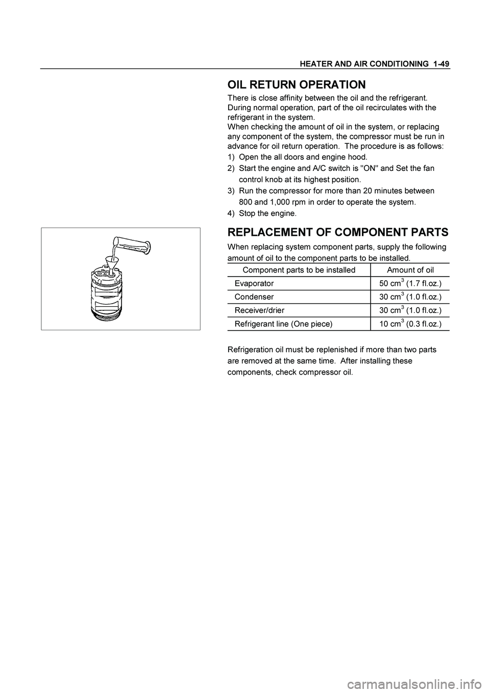
There is close affinity between the oil and the refrigerant.
During normal operation, part of the oil recirculates with the
refrigerant in the system.
When checking the amount of oil in the system, or replacing
any component of the system, the compressor must be run in
advance for oil return operation. The procedure is as follows:
1) Open the all doors and engine hood.
2) Start the engine and A/C switch is "ON" and Set the fan
control knob at its highest position.
3) Run the compressor for more than 20 minutes between
800 and 1,000 rpm in order to operate the system.
4) Stop the engine.
REPLACEMENT OF COMPONENT PARTS
When replacing system component parts, supply the following
amount of oil to the component parts to be installed.
Component parts to be installed Amount of oil
Evaporator 50 cm3 (1.7 fl.oz.)
Condenser 30 cm3 (1.0 fl.oz.)
Receiver/drier 30 cm3 (1.0 fl.oz.)
Refrigerant line (One piece) 10 cm3 (0.3 fl.oz.)
Refrigeration oil must be replenished if more than two parts
are removed at the same time. After installing these
components, check compressor oil.
Page 3380 of 4264
11B – 34 ANTITHEFT SYSTEM
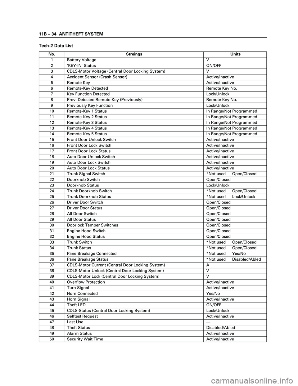
Tech-2 Data List
No. Streings Units
1 Battery Voltage V
2‘KEY-IN’ Status ON/OFF
3 CDLS-Motor Voltage (Central Door Locking System) V
4 Accident Sensor (Crash Sensor) Active/Inactive
5 Remote Key Active/Inactive
6 Remote-Key Detected Remote Key No.
7 Key Function Detected Lock/Unlock
8 Prev. Detected Remote-Key (Previously) Remote Key No.
9 Previously Key Function Lock/Unlock
10 Remote-Key 1 Status In Range/Not Programmed
11 Remote-Key 2 Status In Range/Not Programmed
12 Remote-Key 3 Status In Range/Not Programmed
13 Remote-Key 4 Status In Range/Not Programmed
14 Remote-Key 5 Status In Range/Not Programmed
15 Front Door Unlock Switch Active/Inactive
16 Front Door Lock Switch Active/Inactive
17 Front Door Lock Status Active/Inactive
18 Auto Door Unlock Switch Active/Inactive
19 Auto Door Lock Switch Active/Inactive
20 Auto Door Lock Status Active/Inactive
21 Trunk Signal Switch *Not used Open/Closed
22 Doorknob Switch Open/Closed
23 Doorknob Status Lock/Unlock
24 Trunk Doorknob Switch *Not used Open/Closed
25 Trunk Doorknob Status *Not used Lock/Unlock
26 Driver Door Switch Open/Closed
27 Driver Door Status Open/Closed
28 All Door Switch Open/Closed
29 All Door Status Open/Closed
30 Doorlock Tamper Switches Open/Closed
31 Engine Hood Switch Open/Closed
32 Engine Hood Status Open/Closed
33 Trunk Switch *Not used Open/Closed
34 Trunk Status *Not used Open/Closed
35 Pane Breakage Connected *Not used Yes/No
36 Pane Breakage Status *Not used Disabled/Abled
37 CDLS-Motor Current (Central Door Locking System) A
38 CDLS-Motor Unlock (Central Door Locking System) V
39 CDLS-Motor Lock (Central Door Locking System) V
40 Overflow Protection Active/Inactive
41 Turn Signal Active/Inactive
42 Horn Connected Yes/No
43 Horn Signal Active/Inactive
44 Theft LED ON/OFF
45 CDLS-Status (Central Door Locking System) Lock/Unlock
46 Selftest Request Active/Inactive
47 Last Use—
48 Theft Status Disabled/Abled
49 Alarm Status Active/Inactive
50 Security Wait Time Active/Inactive
Page 3473 of 4264
POWER-ASSISTED STEERING SYSTEM 3B-43
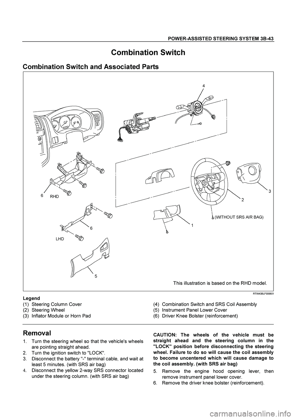
Combination Switch
Combination Switch and Associated Parts
This illustration is based on the RHD model.
RTW43BLF000601
Legend
(1) Steering Column Cover
(2) Steering Wheel
(3) Inflator Module or Horn Pad
(4) Combination Switch and SRS Coil Assembly
(5) Instrument Panel Lower Cover
(6) Driver Knee Bolster (reinforcement)
Removal
1. Turn the steering wheel so that the vehicle's wheels
are pointing straight ahead.
2. Turn the ignition switch to "LOCK".
3. Disconnect the battery "-" terminal cable, and wait a
t
least 5 minutes. (with SRS air bag)
4.
Disconnect the yellow 2-way SRS connector located
under the steering column. (with SRS air bag)
CAUTION: The wheels of the vehicle must be
straight ahead and the steering column in the
"LOCK" position before disconnecting the steering
wheel. Failure to do so will cause the coil assembly
to become uncentered which will cause damage to
the coil assembly. (with SRS air bag)
5. Remove the engine hood opening lever, then
remove instrument panel lower cover.
6. Remove the driver knee bolster (reinforcement).
Page 3477 of 4264
POWER-ASSISTED STEERING SYSTEM 3B-47
6. Install the driver knee bolster assembly.
7. Install the steering lower cover and engine hood
opening lever.
8. Install the steering wheel and align the setting
marks.
Refer to the adjustment method in case a mark is
not attached in this section.
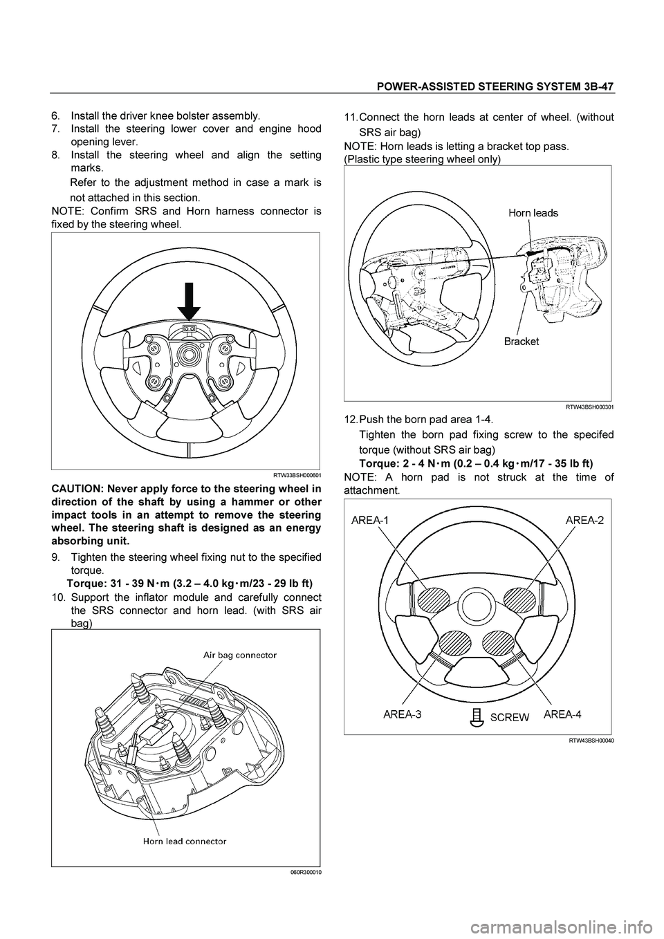
NOTE: Confirm SRS and Horn harness connector is
fixed by the steering wheel.
RTW33BSH000601
CAUTION: Never apply force to the steering wheel in
direction of the shaft by using a hammer or othe
r
impact tools in an attempt to remove the steering
wheel. The steering shaft is designed as an energy
absorbing unit.
9. Tighten the steering wheel fixing nut to the specified
torque.
Torque: 31 - 39 N�
�� �m (3.2 – 4.0 kg�
�� �m/23 - 29 lb ft)
10. Support the inflator module and carefully connec
t
the SRS connector and horn lead. (with SRS air
bag)
060R300010
11. Connect the horn leads at center of wheel. (without
SRS air bag)
NOTE: Horn leads is letting a bracket top pass.
(Plastic type steering wheel only)
RTW43BSH000301
12. Push the born pad area 1-4.
Tighten the born pad fixing screw to the specifed
torque (without SRS air bag)
Torque: 2 - 4 N�
�� �
m (0.2 – 0.4 kg�
�� �
m/17 - 35 lb ft)
NOTE: A horn pad is not struck at the time o
f
attachment.
RTW43BSH00040
Page 3478 of 4264
3B-48 POWER-ASSISTED STEERING SYSTEM
13. Align the each snap stud of driver air bag to the hole
of steering wheel. (with SRS air bag)
060R300030
060R300020
14. Push the SRS air bag area1 and area2. At that time
confirm the audible noise of each stud. (with SRS ai
r
bag)
060R300036
15. Enable the SRS (Refer to "Enabling the SRS" in this
section). (with SRS air bag)
16. Install driver knee bolster (reinforcement).
17. Install instrument panel lower cover then Install the
engine hood opening lever.
18. Connect the SRS connector. (with SRS air bag)
19. Connect the battery "-" terminal cable. (with SRS ai
r
bag)
20. Turn the ignition switch to "ON" while watching
warning light and check the light should flash 7 times
and then go off. If lamp does not operate correctly,
refer to Restraints section.
Page 3480 of 4264
3B-50 POWER-ASSISTED STEERING SYSTEM
CAUTION: The wheels of the vehicle must be
straight ahead and the steering column in the
"LOCK" position before disconnecting the steering
wheel. Failure to do so will cause the coil assembly
to become uncentered which will cause damage to
the coil assembly. (with SRS air bag)
5. Remove the engine hood opening lever and
steering lower cover.
6. Remove driver knee bolster (reinforcement).
7. Disable the SRS (Refer to "Disabling the SRS" in
this section). (with SRS air bag)
8. Check the both side hole of the steering cover. (with
SRS air bag)
060R300025
9. Check the position of the pins in a hole. Push the
pin in the direction of an arrow. (with SRS air bag)
060R300032
10. Push the four pins at �
5�
6 mm bar. (with SRS ai
r
bag)
060R300031
11. Cancel the lock four pins. (with SRS air bag)
12. Loosen the horn pad fixing screw at the rear of the
steering wheel (without SRS air bag).
430R300009
Page 3483 of 4264
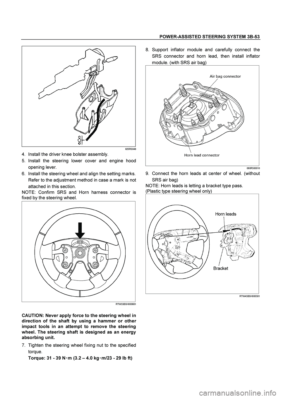
POWER-ASSISTED STEERING SYSTEM 3B-53
825RS048
4. Install the driver knee bolster assembly.
5. Install the steering lower cover and engine hood
opening lever.
6. Install the steering wheel and align the setting marks.
Refer to the adjustment method in case a mark is no
t
attached in this section.
NOTE: Confirm SRS and Horn harness connector is
fixed by the steering wheel.
RTW33BSH000601
CAUTION: Never apply force to the steering wheel in
direction of the shaft by using a hammer or othe
r
impact tools in an attempt to remove the steering
wheel. The steering shaft is designed as an energy
absorbing unit.
7. Tighten the steering wheel fixing nut to the specified
torque.
Torque: 31 - 39 N�
�� �
m (3.2 – 4.0 kg�
�� �
m/23 - 29 lb ft)
8. Support inflator module and carefully connect the
SRS connector and horn lead, then install inflato
r
module. (with SRS air bag)
060R300010
9. Connect the horn leads at center of wheel. (without
SRS air bag)
NOTE: Horn leads is letting a bracket type pass.
(Plastic type steering wheel only)
RTW43BSH000301