Page 1146 of 4264
6A – 6 ENGINE MECHANICAL
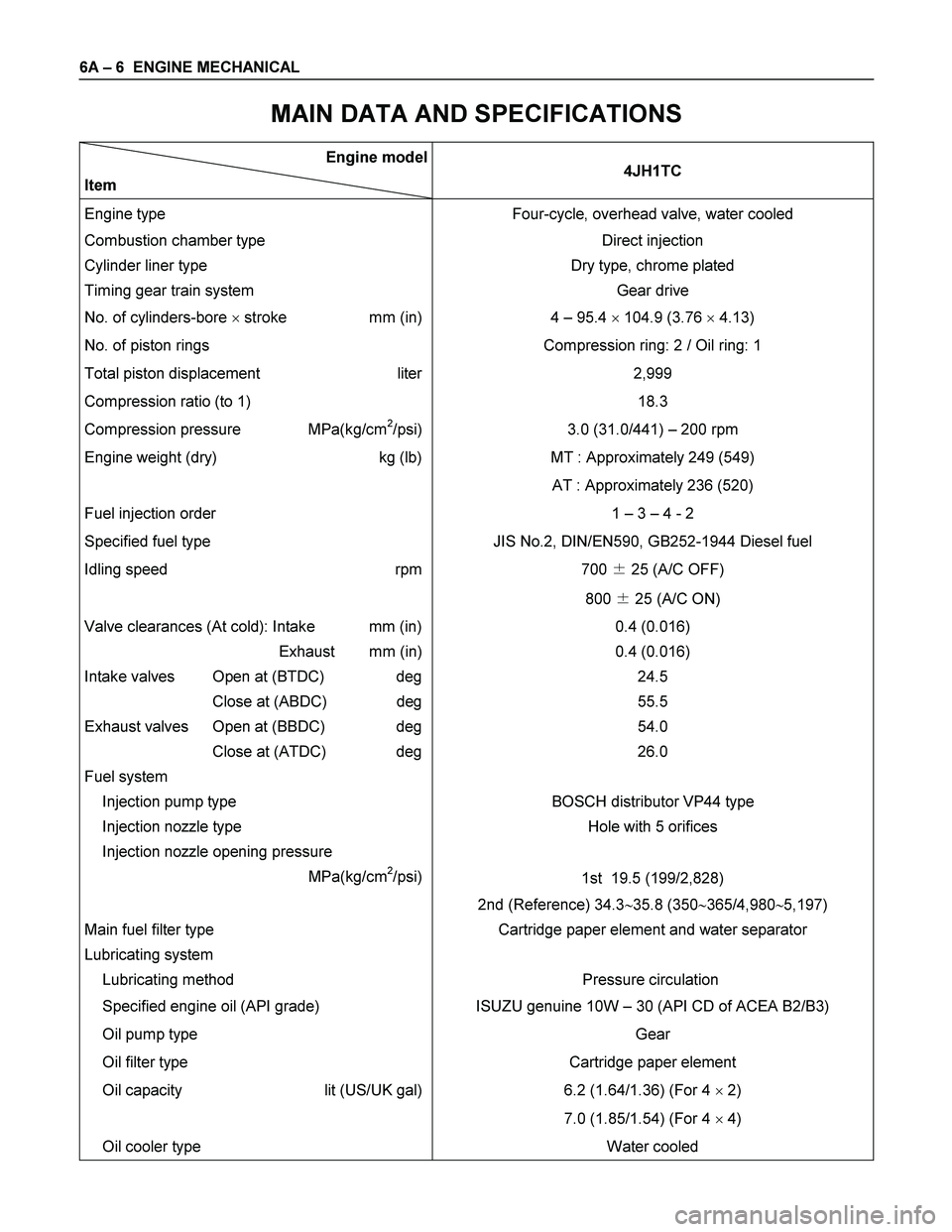
MAIN DATA AND SPECIFICATIONS
Engine model
Item 4JH1TC
Engine type Four-cycle, overhead valve, water cooled
Combustion chamber type Direct injection
Cylinder liner type
Timing gear train system Dry type, chrome plated
Gear drive
No. of cylinders-bore � stroke mm (in) 4 – 95.4 � 104.9 (3.76 � 4.13)
No. of piston rings Compression ring: 2 / Oil ring: 1
Total piston displacement liter
Compression ratio (to 1) 2,999
18.3
Compression pressure MPa(kg/cm2/psi) 3.0 (31.0/441) – 200 rpm
Engine weight (dry) kg (lb) MT : Approximately 249 (549)
AT : Approximately 236 (520)
Fuel injection order 1 – 3 – 4 - 2
Specified fuel type JIS No.2, DIN/EN590, GB252-1944 Diesel fuel
Idling speed rpm
700 � 25 (A/C OFF)
800 � 25 (A/C ON)
Valve clearances (At cold): Intake mm (in)
Exhaust mm (in)
Intake valves Open at (BTDC) deg
Close at (ABDC) deg
Exhaust valves Open at (BBDC) deg
Close at (ATDC) deg
Fuel system
Injection pump type 0.4 (0.016)
0.4 (0.016)
24.5
55.5
54.0
26.0
BOSCH distributor VP44 type
Injection nozzle type
Injection nozzle opening pressure
MPa(kg/cm
2/psi)Hole with 5 orifices
1st 19.5 (199/2,828)
2nd (Reference) 34.3�35.8 (350�365/4,980�5,197)
Main fuel filter type
Lubricating system
Lubricating method Cartridge paper element and water separator
Pressure circulation
Specified engine oil (API grade) ISUZU genuine 10W – 30 (API CD of ACEA B2/B3)
Oil pump type
Oil filter type Gear
Cartridge paper element
Oil capacity lit (US/UK gal)
6.2 (1.64/1.36) (For 4 � 2)
7.0 (1.85/1.54) (For 4 � 4)
Oil cooler type Water cooled
Page 1164 of 4264
6A – 24 ENGINE MECHANICAL
SERVICING
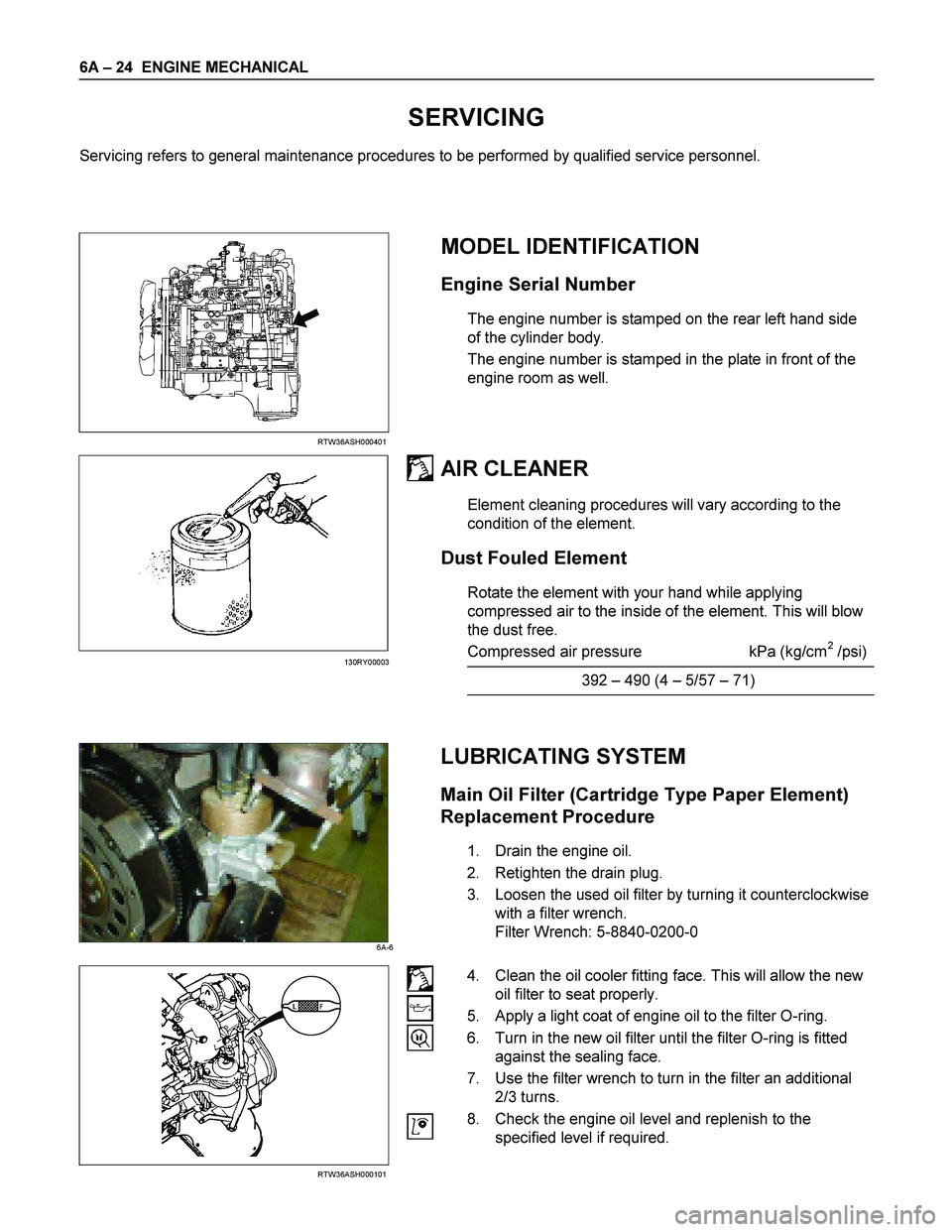
Servicing refers to general maintenance procedures to be performed by qualified service personnel.
RTW36ASH000401
MODEL IDENTIFICATION
Engine Serial Number
The engine number is stamped on the rear left hand side
of the cylinder body.
The engine number is stamped in the plate in front of the
engine room as well.
AIR CLEANER
Element cleaning procedures will vary according to the
condition of the element.
Dust Fouled Element
Rotate the element with your hand while applying
compressed air to the inside of the element. This will blow
the dust free.
Compressed air pressure kPa (kg/cm
2 /psi)
392 – 490 (4 – 5/57 – 71)
LUBRICATING SYSTEM
Main Oil Filter (Cartridge Type Paper Element)
Replacement Procedure
1. Drain the engine oil.
2. Retighten the drain plug.
3. Loosen the used oil filter by turning it counterclockwise
with a filter wrench.
Filter Wrench: 5-8840-0200-0
RTW36ASH000101
4. Clean the oil cooler fitting face. This will allow the new
oil filter to seat properly.
5. Apply a light coat of engine oil to the filter O-ring.
6. Turn in the new oil filter until the filter O-ring is fitted
against the sealing face.
7. Use the filter wrench to turn in the filter an additional
2/3 turns.
8. Check the engine oil level and replenish to the
specified level if required.
130RY00003
6A-6
Page 1266 of 4264
6A – 126 ENGINE MECHANICAL
LUBRICATION SYSTEM
LUBRICATING OIL FLOW
1. Oil Pump Relief Valve Operating Pressure: 6.2 - 7.8kg/cm 2 (608 - 764Kpa)
2. Regulating Valve Operating Pressure: 5.7 - 6.3kg/cm 2 (558.6 - 617.4Kpa)
3. Oil Cooler Relief Valve Opening Pressure: 2.8 - 3.4kg/cm 2 (270 - 330Kpa)
4. Oil Filter Relief Valve Opening Pressure: 0.8 - 1.2kg/cm 2 (78.4 - 117.6Kpa)
5. Oil Pressure Switch Operating Pressure: 0.3 - 0.5kg/cm 2 (29.4 - 49.0Kpa)
6. Regulating Valve: 1.8 - 2.2kg/cm 2 (176 - 216Kpa)
The 4J series engine has a full flow type lubricating system.
Lubricating oil is pumped from the oil pump to the cylinder body oil gallery through the oil cooler and the oil filter. It is
then delivered to the vital parts of the engine from the cylinder body oil gallery.
Oiling jets installed on the cylinder body spray engine oil to the piston backside faces to achieve maximum piston
cooling effect.
Page 1267 of 4264
ENGINE MECHANICAL 6A – 127
OIL PUMP AND OIL FILTER
RTW46ALF001501
The 4J series engine is equipped with a gear type oil pump.
The oil filter and the water cooled oil cooler integrated a single unit to increase the cooling effect.
Page 1283 of 4264
ENGINE COOLING 6B – 3
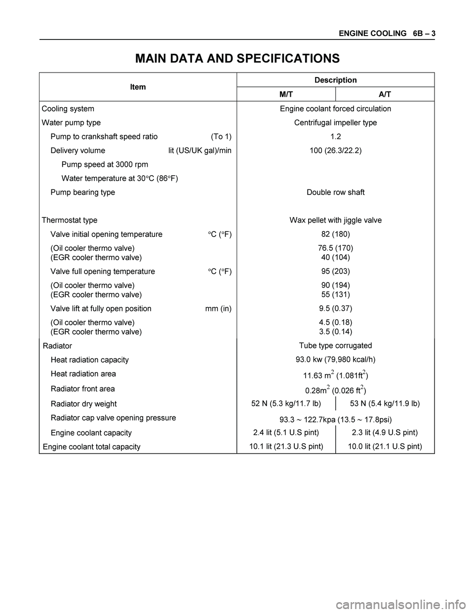
MAIN DATA AND SPECIFICATIONS
Description Item
M/T A/T
Cooling system
Water pump type
Pump to crankshaft speed ratio (To 1)
Delivery volume lit (US/UK gal)/min
Pump speed at 3000 rpm
Water temperature at 30�C (86�F)
Pump bearing type
Thermostat type
Valve initial opening temperature �C (�F)
(Oil cooler thermo valve)
(EGR cooler thermo valve)
Valve full opening temperature �C (�F)
(Oil cooler thermo valve)
(EGR cooler thermo valve)
Valve lift at fully open position mm (in)
(Oil cooler thermo valve)
(EGR cooler thermo valve) Engine coolant forced circulation
Centrifugal impeller type
1.2
100 (26.3/22.2)
Double row shaft
Wax pellet with jiggle valve
82 (180)
76.5 (170)
40 (104)
95 (203)
90 (194)
55 (131)
9.5 (0.37)
4.5 (0.18)
3.5 (0.14)
Radiator Tube type corrugated
Heat radiation capacity 93.0 kw (79,980 kcal/h)
Heat radiation area
11.63 m� (1.081ft�)
Radiator front area
0.28m� (0.026 ft�)
Radiator dry weight 52 N (5.3 kg/11.7 lb) 53 N (5.4 kg/11.9 lb)
Radiator cap valve opening pressure
93.3 � 122.7kpa (13.5 � 17.8psi)
Engine coolant capacity 2.4 lit (5.1 U.S pint) 2.3 lit (4.9 U.S pint)
Engine coolant total capacity 10.1 lit (21.3 U.S pint) 10.0 lit (21.1 U.S pint)
Page 1286 of 4264
6B – 6 ENGINE COOLING
110RS001
RADIATOR
The radiator is a tube type with corrugated fins. In order to
raise the boiling point of the coolant, the radiator is fitted with a
cap in which the valve is operated at 93.3
� 122.7 kPa (13.5 �
17.8 psi) pressure. (No oil cooler provided for M/T)
F06RW005
Antifreeze Solution
NOTE: Antifreeze solution + Water = Total cooling system
capacity.
Total Cooling System Capacity Lit (US / UK gal)
9.4 (2.5/21) 4JA1L/TC
M/T 10.1 (2.7/2.2) 4JH1TC
A/T 10.0 (2.6/2.2) 4JH1TC
See section 0B MAINTENACE AND LUBRICATION.
PTW46BSH000201
NOITE:
To maintain the corrosion resistance of the aluminum
radiator, water and antifreeze must be combined in a 1:1
solution (50% antifreeze and 50% water)
NOTE
Page 1303 of 4264
FUEL SYSTEM 6C – 3
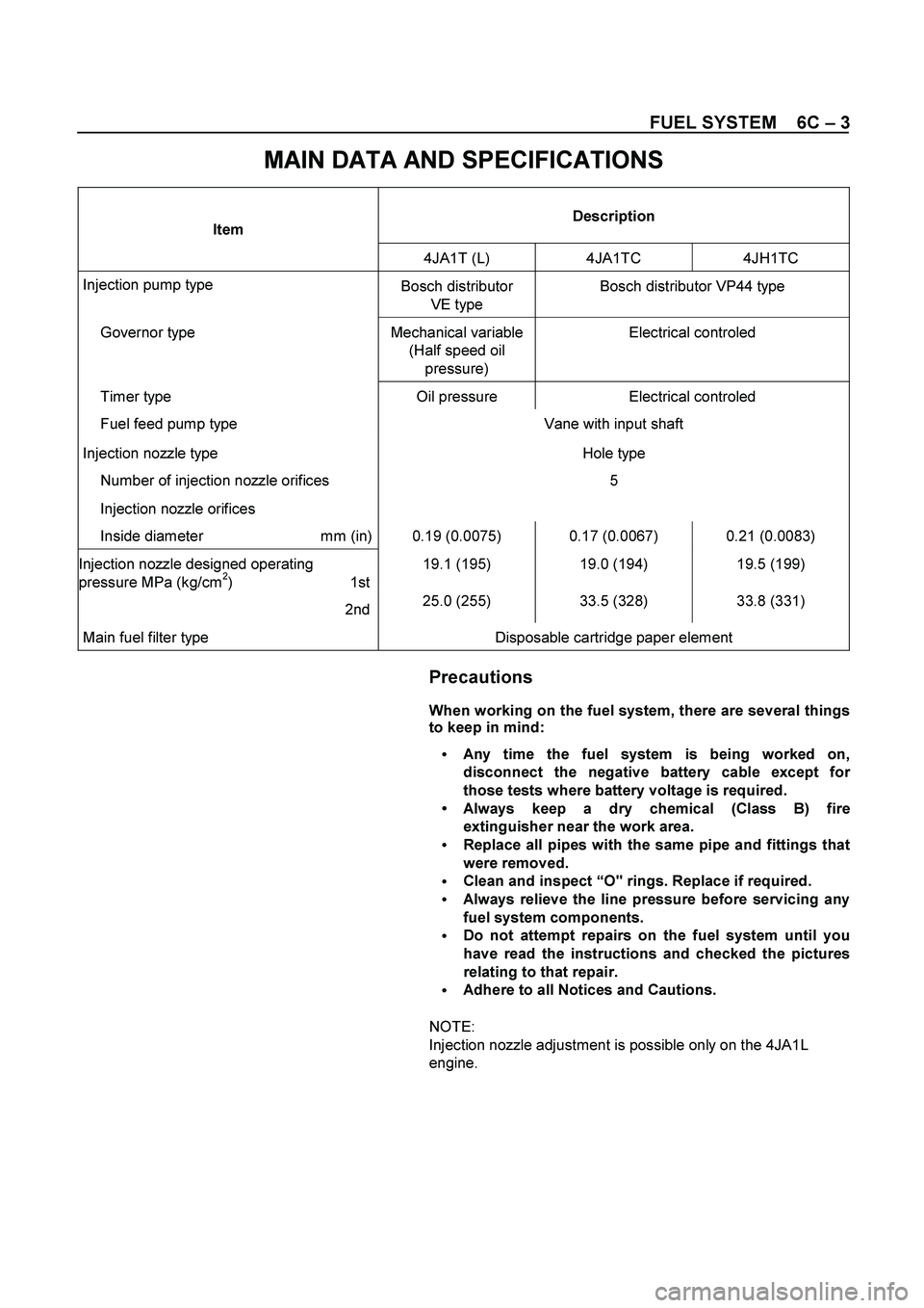
MAIN DATA AND SPECIFICATIONS
Description Item
4JA1T (L) 4JA1TC 4JH1TC
Injection pump type
Bosch distributor
VE type Bosch distributor VP44 type
Governor type Mechanical variable
(Half speed oil
pressure) Electrical controled
Timer type Oil pressure Electrical controled
Fuel feed pump type Vane with input shaft
Injection nozzle type Hole type
Number of injection nozzle orifices 5
Injection nozzle orifices
Inside diameter mm (in) 0.19 (0.0075) 0.17 (0.0067) 0.21 (0.0083)
19.1 (195) 19.0 (194) 19.5 (199) Injection nozzle designed operating
pressure MPa (kg/cm2) 1st
2nd 25.0 (255) 33.5 (328) 33.8 (331)
Main fuel filter type Disposable cartridge paper element
Precautions
When working on the fuel system, there are several things
to keep in mind:
Any time the fuel system is being worked on,
disconnect the negative battery cable except fo
r
those tests where battery voltage is required.
Always keep a dry chemical (Class B) fire
extinguisher near the work area.
Replace all pipes with the same pipe and fittings that
were removed.
Clean and inspect “O" rings. Replace if required.
Always relieve the line pressure before servicing any
fuel system components.
Do not attempt repairs on the fuel system until you
have read the instructions and checked the pictures
relating to that repair.
Adhere to all Notices and Cautions.
NOTE:
Injection nozzle adjustment is possible only on the 4JA1L
engine.
Page 1438 of 4264
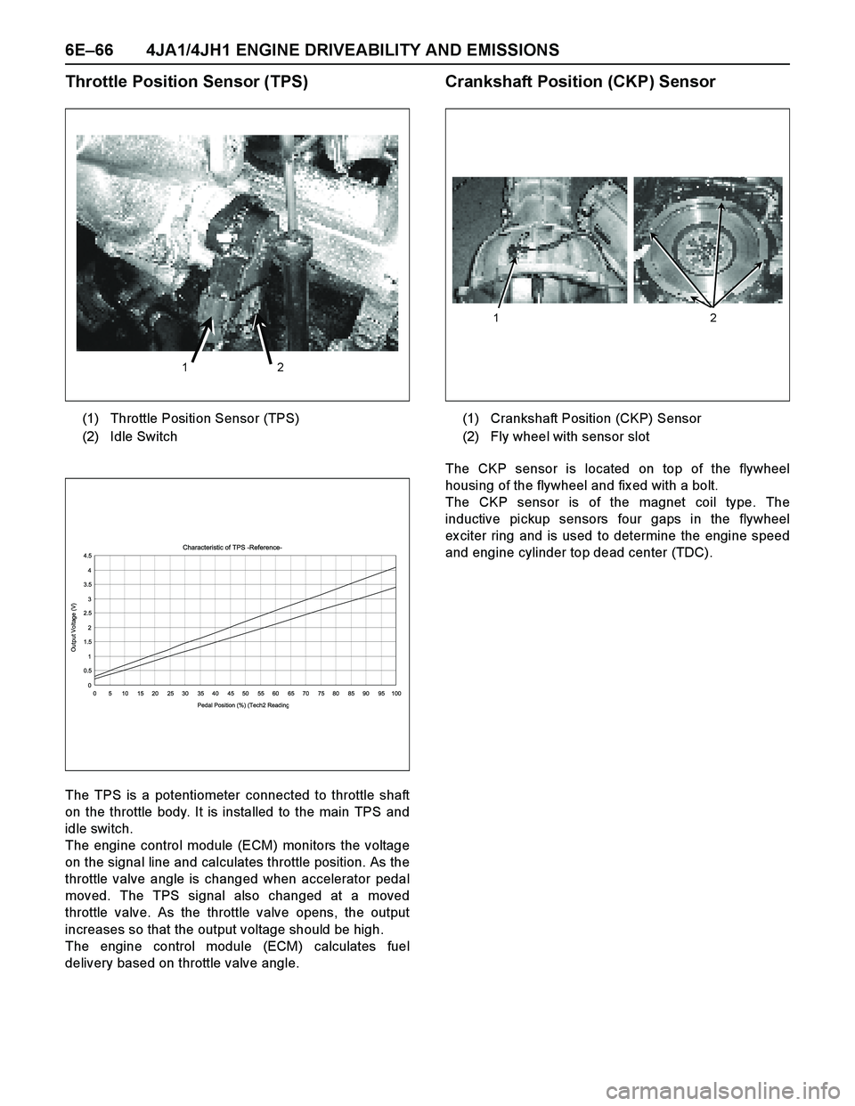
6E–66 4JA1/4JH1 ENGINE DRIVEABILITY AND EMISSIONS
Throttle Position Sensor (TPS)
The TPS is a potentiometer connected to throttle shaft
on the throttle body. It is installed to the main TPS and
idle switch.
The engine control module (ECM) monitors the voltage
on the signal line and calculates throttle position. As the
throttle valve angle is changed when accelerator pedal
moved. The TPS signal also changed at a moved
throttle valve. As the throttle valve opens, the output
increases so that the output voltage should be high.
The engine control module (ECM) calculates fuel
delivery based on throttle valve angle.
Crankshaft Position (CKP) Sensor
The CKP sensor is located on top of the flywheel
housing of the flywheel and fix ed with a bolt.
The CKP sensor is of the magnet coil type. The
inductive pickup sensors four gaps in the flywheel
ex citer ring and is used to determine the engine speed
and engine cylinder top dead center (TDC). (1) Throttle Position Sensor (TPS)
(2) Idle Switch
1 2
Characteristic of TPS -Reference-
0 0.51 1.52 2.53 3.54 4.5
0 5 10 15 20 25 30 35 40 45 50 55 60 65 70 75 80 85 90 95 100
Pedal Position (%) (Tech2 Readin
g
Output Voltage (V)
(1) Crankshaft Position (CKP) Sensor
(2) Fly wheel with sensor slot
1 2