2004 ISUZU TF SERIES Firing
[x] Cancel search: FiringPage 2630 of 4264

6E–54 ENGINE DRIVEABILITY AND EMISSIONS
GENERAL DESCRIPTION FOR ELECTRIC
IGNITION SYSTEM
The engine use two ignition coils, one per two cylinders.
A two wire connector provides a battery voltage primary
supply through the ignition fuse.
The ignition control spark timing is the ECM’s method of
controlling the spark advance and the ignition dwell.
The ignition control spark advance and the ignition dwell
are calculated by the ECM using the following inputs.
Engine speed
Crankshaft position (CKP) sensor
Engine coolant temperature (ECT) sensor
Throttle position sensor
Vehicle speed sensor
ECM and ignition system supply voltage
Ignition coil works to generate only the secondary
voltage be receiving the primary voltage from ECM.
The primary voltage is generated at the coil driver
located in the ECM. The coil driver generate the primary
voltage based on the crankshaft position signal. In
accordance with the crankshaft position signal, ignition
coil driver determines the adequate ignition timing and
also cylinder number to ignite.
Ignition timing is determined the coolant temperature,
intake air temperature, engine speed, engine load,
knock sensor signal, etc.
Spark Plug
Although worn or dirty spark plugs may give satisfactory
operation at idling speed, they frequently fail at higher
engine speeds. Faulty spark plugs may cause poor fuel
economy, power loss, loss of speed, hard starting and
generally poor engine performance. Follow the
scheduled maintenance service recommendations to
ensure satisfactory spark plug performance. Refer to
Maintenance and Lubrication.
Normal spark plug operation will result in brown to
grayish-tan deposits appearing on the insulator portion
of the spark plug. A small amount of red-brown, yellow,
and white powdery material may also be present on the
insulator tip around the center electrode. These
deposits are normal combustion by-products of fuels
and lubricating oils with additives. Some electrode wear
will also occur. Engines which are not running properly
are often referred to as “misfiring.” This means the
ignition spark is not igniting the air/fuel mix ture at the
proper time. While other ignition and fuel system causes
must also be considered, possible causes include
ignition system conditions which allow the spark voltage
to reach ground in some other manner than by jumping
across the air gap at the tip of the spark plug, leaving
the air/fuel mix ture unburned. Misfiring may also occur
when the tip of the spark plug becomes overheated and
ignites the mixture before the spark jumps. This is
referred to as “pre-ignition.”
Spark plugs may also misfire due to fouling, ex cessive
gap, or a cracked or broken insulator. If misfiring occursbefore the recommended replacement interval, locate
and correct the cause.
Carbon fouling of the spark plug is indicated by dry,
black carbon (soot) deposits on the portion of the spark
plug in the cylinder. Ex cessive idling and slow speeds
under light engine loads can keep the spark plug
temperatures so low that these deposits are not burned
off. Very rich fuel mix tures or poor ignition system output
may also be the cause. Refer to DTC P1167.
Oil fouling of the spark plug is indicated by wet oily
deposits on the portion of the spark plug in the cylinder,
usually with little electrode wear. This may be caused by
oil during break-in of new or newly overhauled engines.
Deposit fouling of the spark plug occurs when the
normal red-brown, yellow or white deposits of
combustion by-products become sufficient to cause
misfiring. In some cases, these deposits may melt and
form a shiny glaze on the insulator around the center
electrode. If the fouling is found in only one or two
cylinders, valve stem clearances or intake valve seals
may be allowing ex cess lubricating oil to enter the
cylinder, particularly if the deposits are heavier on the
side of the spark plug facing the intake valve.
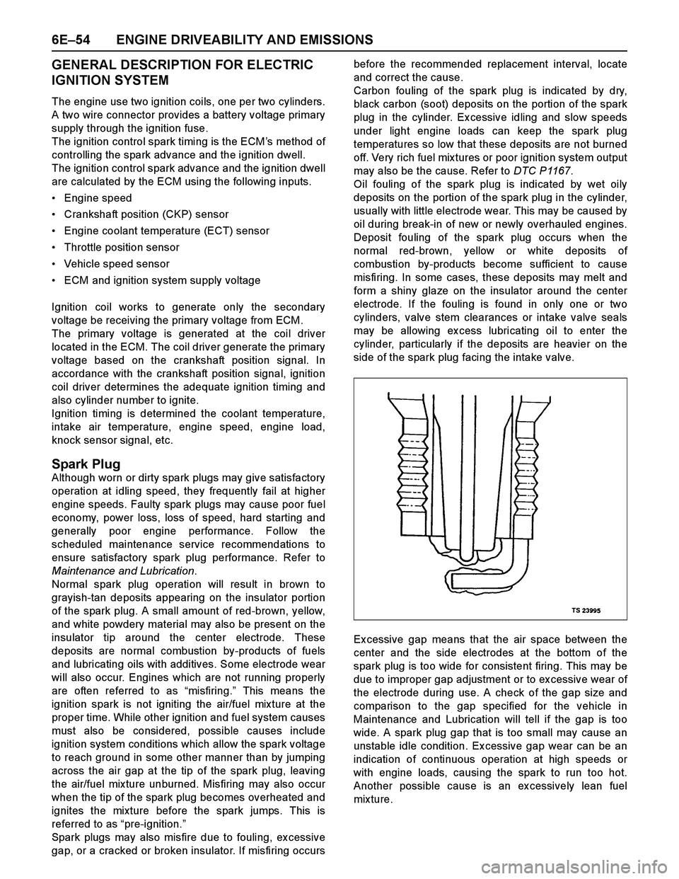
Ex cessive gap means that the air space between the
center and the side electrodes at the bottom of the
spark plug is too wide for consistent firing. This may be
due to improper gap adjustment or to ex cessive wear of
the electrode during use. A check of the gap size and
comparison to the gap specified for the vehicle in
Maintenance and Lubrication will tell if the gap is too
wide. A spark plug gap that is too small may cause an
unstable idle condition. Ex cessive gap wear can be an
indication of continuous operation at high speeds or
with engine loads, causing the spark to run too hot.
Another possible cause is an ex cessively lean fuel
mixture.
Page 2685 of 4264

ENGINE DRIVEABILITY AND EMISSIONS 6E–109
The fuel injector(s).
4. Fuel pressure that drops off during acceleration,
cruise, or hard cornering may case a lean condition.
A lean condition can cause a loss of power, surging,
or misfire. A lean condition can be diagnosed using a
Tech 2 Scan Tool.
Following are applicable to the vehicle with
closed Loop System:
If an ex tremely lean condition occurs, the ox ygen
sensor(s) will stop toggling. The ox ygen sensor
output voltage(s) will drop below 500 mV. Also, the
fuel injector pulse width will increase.
Important: Make sure the fuel system is not
operating in the “Fuel Cut-Off Mode.”
When the engine is at idle, the manifold pressure is
low (high vacuum). This low pressure (high vacuum)
is applied to the fuel pressure regulator diaphragm.
The low pressure (high vacuum) will offset the
pressure being applied to the fuel pressure regulator
diaphragm by the spring inside the fuel pressure
regulator. When this happens, the result is lower fuel
pressure. The fuel pressure at idle will vary slightly
as the barometric pressure changes, but the fuel
pressure at idle should always be less than the fuel
pressure noted in step 2 with the engine OFF.
16.Check the spark plug associated with a particular
fuel injector for fouling or saturation in order to
determine if that particular fuel injector is leaking. If
checking the spark plug associated with a particular
fuel injector for fouling or saturation does not
determine that a particular fuel injector is leaking,
use the following procedure:
Remove the fuel rail, but leave the fuel lines and
injectors connected to the fuel rail. Refer to Fuel
Rail Assembly in On-Vehicle Service.
Lift the fuel rail just enough to leave the fuel
injector nozzles in the fuel injector ports.
Caution: In order to reduce the risk of fire and
personal injury that may result from fuel
spraying on the engine, verify that the fuel rail is
positioned over the fuel injector ports and verify
that the fuel injector retaining clips are intact.
Pressurize the fuel system by connecting a 20
amp fused jumper between B+ and the fuel
pump relay connector.
Visually and physically inspect the fuel
injector nozzles for leaks.
17.A rich condition may result from the fuel pressure
being above 376 kPa (55 psi). A rich condition may
cause a 45 to set. Driveability conditions associatedwith rich conditions can include hard starting
(followed by black smoke) and a strong sulfur smell
in the ex haust.
20.This test determines if the high fuel pressure is due
to a restricted fuel return line or if the high fuel
pressure is due to a faulty fuel pressure regulator.
21.A lean condition may result from fuel pressure below
333 kPa (48 psi). A lean condition may cause a 44 to
set. Driveability conditions associated with lean
conditions can include hard starting (when the
engine is cold), hesitation, poor driveability, lack of
power, surging, and misfiring.
22.Restricting the fuel return line causes the fuel
pressure to rise above the regulated fuel pressure.
Command the fuel pump ON with the scan tool. The
fuel pressure should rise above 376 kPa (55 psi) as
the fuel return line becomes partially closed.
NOTE: Do not allow the fuel pressure to exceed 414
kPa (60 psi). Fuel pressure in excess of 414 kPa (60
psi) may damage the fuel pressure regulator.
Caution: To reduce the risk of fire and personal
injury:
It is necessary to relieve fuel system pressure
before connecting a fuel pressure gauge.
Refer to Fuel Pressure Relief Procedure,
below.
A small amount of fuel may be released when
disconnecting the fuel lines. Cover fuel line
fittings with a shop towel before
disconnecting, to catch any fuel that may leak
out. Place the towel in an approved container
when the disconnect is completed.
Fuel Pressure Relief Procedure
1. Remove the fuel cap.
2. Located on the intake manifold which is at the top
right part of the engine.
3. Start the engine and allow it to stall.
4. Crank the engine for an additional 3 seconds.
Fuel Pressure Gauge Installation
1. Remove the fuel pressure fitting cap.
2. Install fuel pressure gauge 5-8840-0378-0 to the
fuel feed line located on the upper right side of the
engine.
3. Reinstall the fuel pump relay.