Page 1836 of 4264

Engine Noisy
Abnormal engine noise often consists of various noises
originating in rotating parts, sliding parts and othe
r
moving parts of the engine. It is, th")
6A-12 ENGINE MECHANICAL (6VE1 3.5L)
Engine Noisy
Abnormal engine noise often consists of various noises
originating in rotating parts, sliding parts and othe
r
moving parts of the engine. It is, therefore, advisable to
locate the source of noise systematically.
Symptom Possible Cause Action
Noise from crank journals or from
crank bearings
(Faulty crank journals and crank
bearings usually make dull noise that
becomes more evident when
accelerating) Oil clearance increased due to worn
crank journals or crank bearings Replace crank bearings and
crankshaft or regrind crankshaft and
install the undersize bearing
Crankshaft out of round Replace crank bearings and
crankshaft or regrind crankshaft and
install the undersize bearing
Crank bearing seized Crank bearing seized Replace crank
bearings and crankshaft or regrind
crankshaft and install the undersize
bearing
Troubleshooting Procedure
Short out each spark plug in sequence using insulated
spark plug wire removers. Locate cylinder with defective
bearing by listening for abnormal noise that stops when
spark plug is shorted out.
Symptom Possible Cause Action
Noise from connecting rods or from
connecting rod bearings
(Faulty connecting rods or connecting
rod bearings usually make an
abnormal noise slightly higher than
the crank bearing noise, which
becomes more evident when engine
is accelerated) Bearing or crankshaft pin worn Replace connecting rod bearings and
crankshaft or regrind crankshaft pin
and install the undersize bearing
Crankpin out of round Replace connecting rod bearings and
crankshaft or regrind crankshaft pin
and install the undersize bearing
Connecting rod bent Correct or replace
Connecting rod bearing seized Replace connecting rod bearings and
crankshaft or regrind crankshaft pin
and install the undersize bearing
Page 1841 of 4264
 6A-17
Engine Oil Consumption Excessive
Symptom Possible Cause Action
Oil leaking Oil pan drain plug loose Retighten or replace gasket
Crankcase fixing bolts loose")
ENGINE MECHANICAL (6VE1 3.5L) 6A-17
Engine Oil Consumption Excessive
Symptom Possible Cause Action
Oil leaking Oil pan drain plug loose Retighten or replace gasket
Crankcase fixing bolts loosened Retighten
Oil pan setting bolts loosened Retighten
Oil pan gasket broken Replace gasket
Front cover retaining bolts loose or
gasket broken Retighten or replace gasket
Head cover fixing bolts loose or
gasket broken Retighten or replace gasket
Oil filter adapter cracked Replace
Oil filter attachings bolt loose or
rubber gasket broken Retighten or replace oil filter
Oil cooler broken Replace
Crankshaft front or rear oil seal
defective Replace oil seal
Oil pressure unit loose or broken Retighten or replace
Blow–by gas hose broken Replace hose
Positive Crankcase Ventilation Valve
clogged Clean
Engine/Transmission coupling failed Replace oil seal
Oil leaking into combustion chambers
due to poor seal in valve system Valve stem oil seal defective Replace
Valve stem or valve guide worn Replace valve and valve guide
Oil leaking into combustion chambers
due to poor seal in cylinder parts Cylinders and pistons worn
excessively Replace cylinder body assembly and
pistons
Piston ring gaps incorrectly
positioned Correct
Piston rings set with wrong side up Correct
Piston ring sticking Replace cylinder body assembly and
pistons
Piston ring and ring groove worn Replace pistons and others
Return ports in oil rings clogged Clean piston and replace rings
Positive Crankcase Ventilation
System malfunctioning Positive Crankcase Ventilation Valve
clogged Clean
Others Improper oil viscosity Use oil of recommended S.A.E.
viscosity
Continuous high speed driving and/or
severe usage such as trailer towing Continuous high speed operation
and/or severe usage will normally
cause increased oil consumption
Page 1842 of 4264

Fuel Consumption Excessive
Symptom Possible Cause Action
Trouble in fuel system Mixture too rich or too lean due to
trouble in fuel injection system Refer to")
6A-18 ENGINE MECHANICAL (6VE1 3.5L)
Fuel Consumption Excessive
Symptom Possible Cause Action
Trouble in fuel system Mixture too rich or too lean due to
trouble in fuel injection system Refer to “Abnormal Combustion"
Fuel cut function does not work Refer to “Abnormal Combustion"
Trouble in ignition system Misfiring or abnormal combustion due
to trouble in ignition system Refer to “Hard Start" or “Abnormal
Combustion"
Others Engine idle speed too high Reset to Section 6E
Returning of accelerator control
sluggish Correct
Fuel system leakage Correct or replace
Clutch slipping Correct
Brake drag Correct
Selection of transmission gear
incorrect Caution operator of incorrect gear
selection
Lubrication Problems
Symptom Possible Cause Action
Oil pressure too low Wrong oil in use Replace with correct engine oil
Relief valve sticking Replace
Oil pump not operating properly Correct or replace
Oil pump strainer clogged Clean or replace strainer
Oil pump worn Replace
Oil pressure gauge defective Correct or replace
Crankshaft bearing or connecting rod
bearing worn Replace
Oil contamination Wrong oil in use Replace with correct engine oil
Oil filter clogged Replace oil filter
Cylinder head gasket damage Replace gasket
Burned gases leaking Replace piston and piston rings or
cylinder body assembly
Oil not reaching valve system Oil passage in cylinder head or
cylinder body clogged Clean or correct
Page 1843 of 4264
ENGINE MECHANICAL (6VE1 3.5L) 6A-19
Engine Oil Pressure Check
1. Check for dirt, Fuel or water in the engine oil.
a. Check the viscosity of the oil.
b. Check the viscosity of the oil.
c. Change the oil if the viscosity is outside the
specified standard.
d. Refer to the “Maintenance and Lubrication"
section of this manual.
2. Check the engine oil level.
The level should fall somewhere between the
“ADD" and the “FULL" marks on the oil level
dipstick.
If the oil level does not reach the “ADD" mark on
the oil level dipstick, engine oil must be added.
3. Remove the oil pressure unit.
4. Install an oil pressure gauge.
5. Start the engine and allow the engine to reach
normal operating temperature (About 80�C).
6. Measure the oil pressure.
Oil pressure should be:
392�
�� �550 kPa (56.9�
�� �80.4 psi) at 3000 rpm.
7. Stop the engine.
8. Remove the oil pressure gauge.
9. Install the oil pressure unit.
10. Start the engine and check for leaks.
Page 1845 of 4264
 6A-21
Cylinder Head Cover LH
Removal
1. Disconnect battery ground cable.
2. Disconnect positive crankcase ventilation hose.
3. Remove camshaft angle sensor connecto")
ENGINE MECHANICAL (6VE1 3.5L) 6A-21
Cylinder Head Cover LH
Removal
1. Disconnect battery ground cable.
2. Disconnect positive crankcase ventilation hose.
3. Remove camshaft angle sensor connector.
4. Remove ground cable fixing bolt on cylinder head
cover.
5. Ignition coil connector and ignition coil.
� Disconnect the three connectors from the
ignition coils.
� Remove harness bracket bolt on cylinder head
cover.
� Remove fixing bolts on ignition coils.
060RW078
Legend
(1) Ignition Coil Connector
(2) Bolt
(3) Ignition Coil Assemblies
6. Remove fixing bolt for fuel injector harness
bracket.
7. Remove eight fixing bolts, then the cylinder head
cover.
010RW001
Installation
1. Install cylinder head cover.
� Clean the sealing surface of cylinder head and
cylinder head cover to remove oil and sealing
materials completely.
� Apply sealant (TB-1207B or equivalent) of bead
diameter 2-3 mm at eight place of arched area
of camshaft bracket on front and rear sides.
� The cylinder head cover must be installed with
in 5 minutes after sealant application to preven
t
hardening of sealant.
� Tighten bolts to the specified torque.
Torque : 9 N�
�� �m (0.9 kg�
�� �m/7 lb ft)
010RW006
Page 1846 of 4264
6A-22 ENGINE MECHANICAL (6VE1 3.5L)
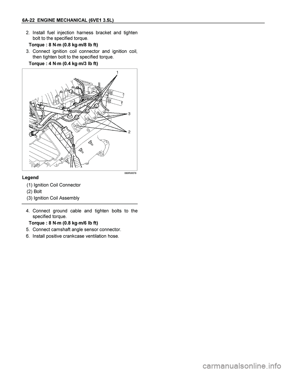
2. Install fuel injection harness bracket and tighten
bolt to the specified torque.
Torque : 8 N�
�� �m (0.8 kg�
�� �m/8 lb ft)
3. Connect ignition coil connector and ignition coil,
then tighten bolt to the specified torque.
Torque : 4 N�
�� �m (0.4 kg�
�� �m/3 lb ft)
060RW078
Legend
(1) Ignition Coil Connector
(2) Bolt
(3) Ignition Coil Assembly
4. Connect ground cable and tighten bolts to the
specified torque.
Torque : 8 N�
�� �m (0.8 kg�
�� �m/6 lb ft)
5. Connect camshaft angle sensor connector.
6. Install positive crankcase ventilation hose.
Page 1847 of 4264
 6A-23
Cylinder Head Cover RH
Removal
1. Disconnect battery ground cable.
2. Remove air cleaner duct assembly.
3. Disconnect ventilation hose from cylinder head
cove")
ENGINE MECHANICAL (6VE1 3.5L) 6A-23
Cylinder Head Cover RH
Removal
1. Disconnect battery ground cable.
2. Remove air cleaner duct assembly.
3. Disconnect ventilation hose from cylinder head
cover.
4. Disconnect three ignition coil connectors from
ignition coils and remove harness bracket bolts on
cylinder head cover then remove ignition coil fixing
bolts on ignition coils and remove ignition coils.
5. Remove heater pipe fixing bolts from the bracket.
6. Disconnect fuel injector harness connector then
remove fuel injector harness bracket bolt.
7. Remove eight fixing bolts then the cylinder head
cover.
010RW002
Installation
1. Install cylinder head cover.
� Clean the sealing surface of cylinder head and
cylinder head cover to remove oil and sealing
materials completely.
� Apply sealant (TB-1207B or equivalent) of bead
diameter 2‐3 mm at eight place of arched
area of camshaft bracket on front and rea
r
sides.
� The cylinder head cover must be installed
within 5 minutes after sealant application to
prevent premature hardening of sealant.
� Tighten bolts to the specified torque.
Torque : 9 N�
�� �m (0.9 kg�
�� �m/7 lb ft)
014RW019
2. Install exhaust gas recirculation pipe and tighten to
specified torque.
Torque :
Exhaust manifold side: 29 N�
�� �m (3.0 kg�
�� �m/21 lb ft)
Flare nut: 44 N�
�� �m (4.5 kg�
�� �m/33 lb ft)
Cylinder head side: 20 N�
�� �m (2.0 kg�
�� �m/14 lb ft)
3. Tighten fuel injector harness bracket bolts to
specified torque then reconnect fuel injecto
r
harness connector.
Torque : 8 N�
�� �m (0.8 kg�
�� �m/5.7 lb ft)
4. Install heater pipe bolt to the specified torque.
Torque : 20 N�
�� �m (2.0 kg�
�� �m/14 lb ft)
5. Connect ignition coil connector and tighten ignition
coil fixing bolts to specified torque.
Torque : 4 N�
�� �m (0.4 kg�
�� �m/3 lb ft)
6. Connect ventilation hose to cylinder head.
7. Install air cleaner duct assembly.
Page 1852 of 4264

Crankshaft Pulley
Removal
1. Disconnect battery ground cable.
2. Remove air cleaner assembly.
3. Remove radiator upper fan shroud from radiator.
4. Move serp")
6A-28 ENGINE MECHANICAL (6VE1 3.5L)
Crankshaft Pulley
Removal
1. Disconnect battery ground cable.
2. Remove air cleaner assembly.
3. Remove radiator upper fan shroud from radiator.
4. Move serpentine belt tensioner to loose side using
wrench then remove serpentine belt.
850RW001
Legend
(1) Crankshaft Pulley
(2) Cooling Fan Pulley
(3) Tensioner
(4) Generator
(5) Air Conditioner Compressor
(6) Power Steering Oil Pump
(7) Serpentine Belt
5. Remove cooling fan assembly four fixing nuts,
then the cooling fan assembly.
6. Remove crankshaft pulley assembly using
5�8840�0133�0 crankshaft holder, hold crankshaf
t
pulley then remove center bolt and pulley.
Installation
1. Install crankshaft pulley using 5�8840�0133�0
crankshaft holder, hold the crankshaft pulley and
tighten center bolt to the specified torque.
Torque: 167 N�
�� �m (17.0 kg�
�� �m/123 lb ft)
2. Install cooling fan assembly and tighten bolts/nuts
to the specified torque.
Torque: 25 N�
�� �m (2.5 kg�
�� �m/18 lb ft) for fan pulley
and fan bracket.
Torque: 10 N�
�� �m (1.0 kg�
�� �m/88.5 lb in) for fan and
clutch assembly.
3. Move serpentine belt tensioner to loose side using
wrench, then install serpentine belt to normal
position.
4. Install radiator upper fan shroud.
5. Install air cleaner assembly.
 6A-19
Engine Oil Pressure Check
1. Check for dirt, Fuel or water in the engine oil.
a. Check the viscosity of the oil.
b. Check the viscosity of the oil.
c. Change")