Page 3770 of 4264

Measure Time Lag
1. Fully apply the parking brake.
2. Start the engine. Check idling speed (A/C OFF).
3. Shift the shift lever from “N\" to")
7A3-14 ON-VEHICLE SERVICE (AW30 –40LE)
Measure Time Lag
1. Fully apply the parking brake.
2. Start the engine. Check idling speed (A/C OFF).
3. Shift the shift lever from “N" to “D" range. Using a
stopwatch, measure the time it takes from shifting
the lever until the shock is felt.
Time lag: Less than 0.7 seconds
4. In same manner, measure the time lag for “N"
�
“R".
Time lag: Less than 1.2 seconds
Evaluation
1. If “N" �
“ D" time lag is longer than specified:
Line pressure too low
Forward clutch malfunction
No.2 one-way clutch not operating properly
2. If “N" �
“ R" time lag is longer than specified:
Line pressure too low
Direct clutch malfunction
No.3 brake malfunction
3. If both time lag is longer than specified:
Line pressure too low
Hydraulic Test
RUW37ALH000201
Preparation
1. Warm up the transmission fluid.
2. Remove the transmission case test plug and mount the hydraulic pressure gauge.
Oil pressure gauge: J –29770 –A
NOTE: Perform the test at normal operation fluid
temperature (50 – 80 �
C or 122 – 176 �
F).
Page 3791 of 4264
 7A3-35
Shift Solenoid and Lock-Up Solenoid
Removal
Preparation:
Disconnect negative ( –) battery cable.
Drain the fluid.
Refer to ATF REPL")
ON-VEHICLE SERVICE (AW30 –40LE) 7A3-35
Shift Solenoid and Lock-Up Solenoid
Removal
Preparation:
Disconnect negative ( –) battery cable.
Drain the fluid.
Refer to ATF REPLACEMENT in this section.
1. Remove oil lever gage and oil filler tube.
2. Support transfer case (4
�4) or rear cover (4�2)
with a transmission jack.
3. Remove engine rear mounting nuts.
F07RW008
4. Remove fule pipe heat protector on tansmission
corssmenber.
5. Remove fuel pipe from the crossmenber.
6. Remove transmission crossmenber.
7. Remove the nineteen bolts.
8. Remove oil pan, using seal cutter J –37228.
RUW37ASH002901
NOTE: Do not turn over the transmission as this will
contaminate the valve body with foreign materials in the
bottom of the oil pan.
Remove oil pan by lifting the transmission case.
Oil pan seal cutter: J –37228
Examine particles in oil pan
Remove the magnet and use it to collect any steel
chips.
Look carefully at the chips and particles in the oil
pan and on the magnet to anticipate what type o
f
wear you will find in the transmission:
Steel (magnetic) ..................bearing, gear and
clutch plate wear
Brass (non-magnetic) ..........bushing wear
240RY00008
9. Remove the oil strainer assembly.
244RY00003
Page 3794 of 4264
7A3-38 ON-VEHICLE SERVICE (AW30 –40LE)
2. Remove the oil strainer assembly.
244RY 00003
3. Disconnect the solenoid wiring connectors from the
solenoids.
4. Remove the twenty bolts from the valve body.
5. Remove the valve body assembly and pressure control solenoid.
After removing valve body assembly from the
transmission case, loosen the solenoid clamp
bolt and remove the pressure control solenoid
from the upper valve body assembly.
Also disconnect the harness connector from the
pressure control solenoid.
NOTE:
Two or more persons are required for removal and
installation of the valve body assembly and pressure
control solenoid.
The check valve assembly (1) and the C0
accumulator piston springs (2) will fall from the
transmission case during removal of valve bod
y
assembly.
Protect these parts from damage. The B0 (3), C2 (4),
and B2 (5) accumulator piston and springs may also
fall free and must be protected.
244RY00018
244RY00006
Page 3795 of 4264
ON-VEHICLE SERVICE (AW30 –40LE) 7A3-39
Installation
To install, follow the removal steps in reverse order
noting the following point;
1. Reinstall the parts removed with the valve bod
y
assembly to their assigned positions in the
transmission case (check valve assembly, C0
accumulator pistons, etc). Install the valve bod
y
assembly to the transmission case.
Refer to REASSEMBLY OF MAJO
R
COMPONENTS (2).
2. Solenoid clamp bolt
Torque : 7 N �
��
�
m (61 Ib in)
3. Valve body fixing bolts
Each bolt location and length (mm) is indicated in
the figure.
Torque : 10 N �
��
�
m (87 Ib in)
NOTE: Tighten the bolts toward outside equally.
244R200078
4. Oil strainer fixing bolts
Torque : 10 N �
��
�
m (87 Ib in)
5. Oil pan fixing bolts
Torque : 8 N �
��
�
m (69 Ib in)
Page 3796 of 4264
7A3-40 ON-VEHICLE SERVICE (AW30 –40LE)
Rear Oil Seal (Adapter Housing, 4�
� �
�4)
Removal
1. Remove the front and rear propeller shaft assembly
from the transfer case.
2. Remove the transfer case assembly from the transmission case.
Refer to Section 4 DRIVELINE/AXLE.
3. Using a screwdriver, remove the rear oil seal.
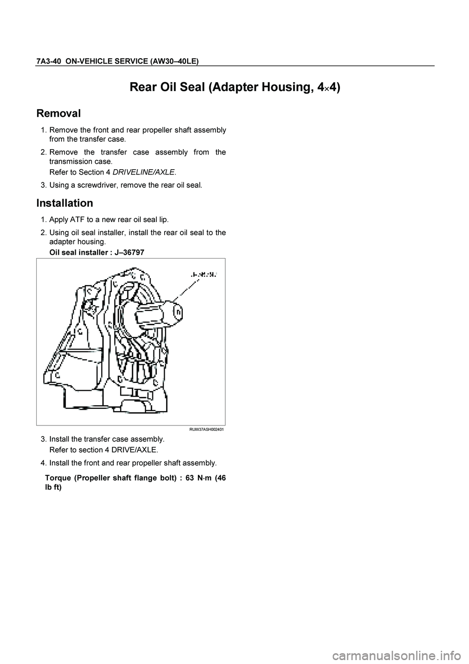
Installation
1. Apply ATF to a new rear oil seal lip.
2. Using oil seal installer, install the rear oil seal to the adapter housing.
Oil seal installer : J –36797
RUW37ASH002401
3. Install the transfer case assembly.
Refer to section 4 DRIVE/AXLE.
4. Install the front and rear propeller shaft assembly.
Torque (Propeller shaft flange bolt) : 63 N �
��
�
m (46
Ib ft)
Page 3798 of 4264
7A3-42 ON-VEHICLE SERVICE (AW30 –40LE)
Transmission Assembly
Transmission and Associated Parts
Legend
(9) Under Cover
(1) Rear Propeller Shaft (10) Flex Plate Torque Converter bolt
(2) Front Propeller Shaft (4WD only) (11) Shift Cable
(3) Middle Exhaust Pipe (12) Rear Mount Rubber
(4) Transfer Case Assembly (4WD only) (13) Heat Protector
(5) Fuel Pipe Clip and Bracket (14) Transmission Crossmember
(6) ATF Pipe and Clip (15) Transmission Assembly (2WD)
(7) Oil Level Gauge and Guide Tube (16) Transmission Assembly (4WD)
(8) Suspension Crossmember
Page 3799 of 4264
 7A3-43
Removal
NOTE: Before removing transmission and transfer
assembly from vehicle, change the transfer mode to
2WD using the 4WD push button switch on dash")
ON-VEHICLE SERVICE (AW30 –40LE) 7A3-43
Removal
NOTE: Before removing transmission and transfer
assembly from vehicle, change the transfer mode to
2WD using the 4WD push button switch on dash panel.
1. Disconnect battery ground cable.
2. Raise and support vehicle with suitable stands.
3. Remove front propeller shaft.(4WD only)
NOTE: Apply alignment marks on the flange at both
front and rear sides.
4. Remove rear propeller shaft.
NOTE: Apply alignment marks on the flange at the
differential side.
401RS023
5. Remove the middle exhaust pipe.
RTW37ASH0001
6. Disconnect the transfer harness connectors and the
clips.(4WD only)
Speed sensor
2W-4W shift actuator
NOTE: Avoid turning the vehicle ignition switch to the
ON position when the 2WD-4WD connector is removed
(battery connected).
If the ignition switch must be turned to the ON position,
the controller must first be removed (memory must be
cleared because the CHECK 4WD INDICATOR will
light).
7. Support transfer case with a transmission jack.(4WD only)
8. Remove the transfer case assembly from the
transmission.(4WD only)
9. Disconnect the shift cable.
10. Remove the fuel pipe clips with the fuel pipes from the brackets and put aside it. Remove the fuel pipe
brakets from the transmission.
P1010010
11. Discinnect the transmission harness connectors
and clips.
12. Remove the oil level gauge and the guide tube.
13. Remove the suspension crossmember.
Page 3804 of 4264
7A3-48 ON-VEHICLE SERVICE (AW30 –40LE)
11. Install the suspension crossmember.
Torque: 65 N �
��
�
m (6.6 kg �
��
�
m/48 lb ft)
12. Install filler tube and insert oil level gage.
Torque: 22 N �
��
�
m (2.2 kg �
��
�
m/16 lb ft)
13. Install select cable by connecting inner cable to
select lever and installing outer cable with bracket.
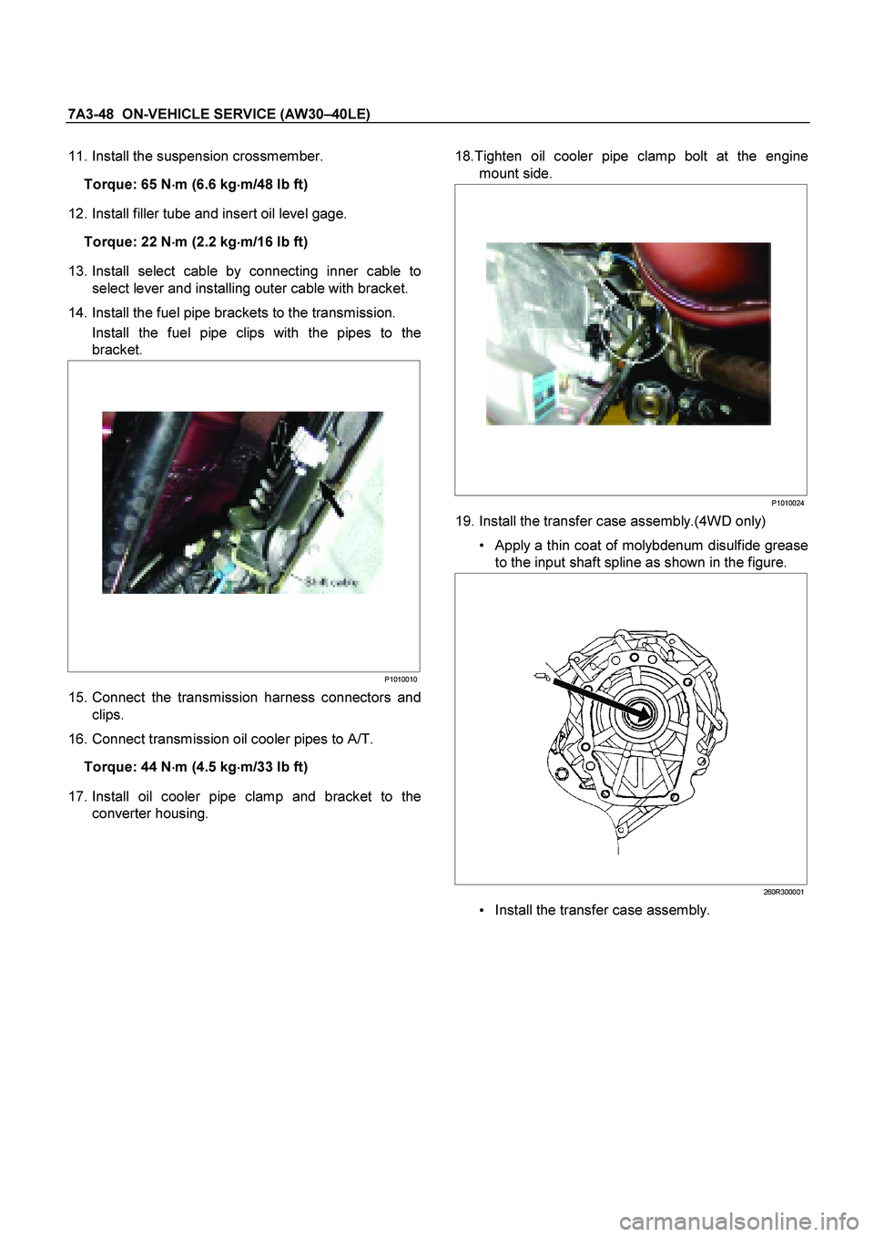
14. Install the fuel pipe brackets to the transmission. Install the fuel pipe clips with the pipes to the
bracket.
P1010010
15. Connect the transmission harness connectors and
clips.
16. Connect transmission oil cooler pipes to A/T.
Torque: 44 N �
��
�
m (4.5 kg
�
��
�
m/33 lb ft)
17. Install oil cooler pipe clamp and bracket to the
converter housing.
18.Tighten oil cooler pipe clamp bolt at the engine
mount side.
P1010024
19. Install the transfer case assembly.(4WD only)
Apply a thin coat of molybdenum disulfide grease
to the input shaft spline as shown in the figure.
260R300001
Install the transfer case assembly.

2. Remove the oil strainer assembly.
244RY 00003
3. Disconnect the solenoid wiring connectors from the
solenoids.
4. Remove the twenty")
 7A3-39
Installation
To install, follow the removal steps in reverse order
noting the following point;
1. Reinstall the parts removed with the valve bod
y")

Transmission Assembly
Transmission and Associated Parts
Legend
(9) Under Cover
(1) Rear Propeller Shaft (10) Flex Plate Torque Co")