Page 3269 of 4264
 and the
3rd gear (9) thrust surfaces.
Install the needle bearing (10) and the 3rd gear (9)
to the mainshaft.
The")
MANUAL TRANSMISSION 7B1-105
12. Apply engine oil to the needle bearing (10) and the
3rd gear (9) thrust surfaces.
Install the needle bearing (10) and the 3rd gear (9)
to the mainshaft.
The 3rd gear dog teeth must be facing the
transmission front side.
226RS056
13. Install 3rd block ring (8).
14. Check and install 3rd-4th synchronizer assembly (7)
by the following steps:
1. Check that the inserts (3) fit snugly into the
clutch hub insert grooves.
2. Check that the insert springs (4) are fitted to the
inserts as shown in the illustration.
3. Check that the clutch hub (5) and the sleeve (6)
slide smoothly.
4. Install the synchronizer assembly to the
mainshaft.
The clutch hub face with the heavy boss must be
facing the 3rd gear side.
226RW221
226RS049
15. Select and install mainshaft snap ring(6) in the
following way:
Select the snap ring which will provide the minimum
clearance between the 3rd-4th clutch hub and the
snap ring.
226RS058
There are three snap ring sizes available.
The snap rings are color coded to indicate their
thickness as shown in the figure.
Page 3271 of 4264
MANUAL TRANSMISSION 7B1-107
Main Data and Specifications
General Specifications
MUA5G MUA5S
Transmission type Fully synchronized forward and reverse gears
Control method Remote control with the gear shift lever on the floor.
Gear ratio: Transmission 1st 4.008 4.357
2nd 2.301 2.502
3rd 1.427 1.501
4th 1.000 1.000
5th 0.828 0.809
Rev. 3.651 3.970
Transmission oil capacity 2.95 lit. (3.12 US qt)
Type of lubricant Engine oil: Refer to the chart in "SECTION 0"
Page 3275 of 4264
MANUAL TRANSMISSION 7B1-111
TROUBLESHOOTING
1. ABNORMAL NOISE
1) NOISY IN NEUTRAL
Checkpoint Trouble Cause Countermeasure
Replenish or replace the gear
oilInsufficient or improper gear
oil NG
Mainshaft splines
Synchronizer clutch hub
splinesReplace the main shaft and
the synchronizer clutch hub
Replace the gear(s)
Replace the flywheel pilot
Worn splines
Worn or scuffed gear tooth
contact surfaces
Flywheel pilot bearingWorn flywheel pilot bearing
Bearings (Mainshaft,
countershaft, and transfer
shaft)
Gears (Mainshaft,
countershaft, reverse idler
gear and transfer gears)
Replace the bearing(s)Worn or broken bearing(s)
OK
NG NG NG NG OK
OK
OK
Gear oil
TransmissionRealign the transmissionTransmission misalignment OK
NG
Page 3276 of 4264
7B1-112 MANUAL TRANSMISSION
2) NOISY OPERATION
Checkpoint Trouble Cause Countermeasure
Replenish or replace the gear
oilInsufficient or improper engine
oil NG
Replace the gear(s)
Replace the gear(s)
Replace the bearing(s)
Gears (Gear whining)Lack of backlash between
meshing gears
Free running gears seizing on
the thrust face or the inner
face
Bearings (Hissing, thumping
or bumping)Worn or broken bearing(s)
Gears (Squealing at high
speeds)
Replace the gear(s)Gears (Growling, humming, or
grinding)Worn, chipped, or cracked
gear(s)
NG NG NG NG OK
OK
OK OK
Gear oil (Metallic rattling)
Page 3277 of 4264
MANUAL TRANSMISSION 7B1-113
2. HARD SHIFTING
Checkpoint Trouble Cause Countermeasure
Change lever play
Clutch pedal free play
Repair or replace the
applicable parts and regrease
Readjust the clutch pedal free
play
Worn change lever sliding
portions
Improper clutch pedal free
play
Change lever operationRepair or regrease the change
lever assembly
Replenish or replace the
engine oil
Hard operating change lever
caused insufficient grease
Insufficient or improper gear
oil
OK
OKNG NG NG NG
OK OKGear oil
Continued on the next page
Shift rod and quadrant box
sliding faces, and other partsReplace the shidt rod and/or
the quadrant boxWorn shift rod and/or sliding
faces
Repair or replace the sleeveSleeve movement failure
NG NG
OKShift block sleeve movement
Page 3281 of 4264
MANUAL TRANSMISSION 7B1-117
4. OIL LEAKAGE
Checkpoint Trouble Cause Countermeasure
Gear oilReplace the gear oilImproper gear oil
Drain plug and/or filler plugTighten the plug(s) and
replenish the oil
Drain the oil to the correct
level
Loose plug(s)
Oil level too high
OKNG NG NG
OK OKOil level
Rear cover oil seal
Air breather
Replace the oil seal
Install the air breather
Replace the air breather
Worn or scratched oil seal
Air breather not installed
Air breather clogged
Front cover oil sealReplace the oil seal
Replace the gasket(s)
Worn or scratched oil seal
Defective or improperly
installed gasket(s)
OK
NG NG NG NG
OK OKGaskets
Page 3282 of 4264
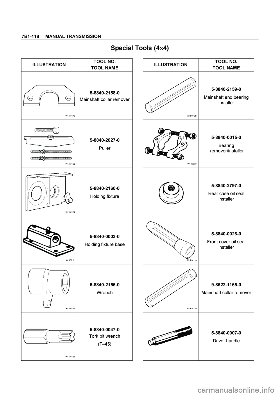
7B1-118 MANUAL TRANSMISSION
Special Tools (4�
�� �
4)
ILLUSTRATION TOOL NO.
TOOL NAME ILLUSTRATION TOOL NO.
TOOL NAME
5-8840-2158-0
Mainshaft collar remover 5-8840-2159-0
Mainshaft end bearing
installer
5-8840-2027-0
Puller 5-8840-0015-0
Bearing
remover/installer
5-8840-2160-0
Holding fixture 5-8840-2797-0
Rear case oil seal
installer
5-8840-0003-0
Holding fixture base 5-8840-0026-0
Front cover oil seal
installer
5-8840-2156-0
Wrench 9-8522-1165-0
Mainshaft collar remover
5-8840-0047-0
Tork bit wrench
(T–45) 5-8840-0007-0
Driver handle
Page 3681 of 4264
 (V6 3.5L) 7A2-1
TRANSMISSION
TRANSMISSION CONTROL SYSTEM (AW30–40LE) (V6 3.5L)
CONTENTS
Service Precaution .....................................")
TRANSMISSION CONTROL SYSTEM (AW30–40LE) (V6 3.5L) 7A2-1
TRANSMISSION
TRANSMISSION CONTROL SYSTEM (AW30–40LE) (V6 3.5L)
CONTENTS
Service Precaution .................................................
7A2-2
General Description ...............................................
7A2-2
Electronic Control Diagram ...............................
7A2-3
Transmission Control Module (TCM) (1/2) ......
7A2-4
Transmission Control Module (TCM) (2/2) ......
7A2-5
TCM Point Table .................................................
7A2-6
TCM Voltage & Resistance Check Sheet .......
7A2-7
Control System Diagram ....................................
7A2-9
Control and Functions ........................................
7A2-10
Gear Shift Control 3rd start ...............................
7A2-10
Mode Type ...........................................................
7A2-10
Mode Selection ....................................................
7A2-10
Comparison of mode ..........................................
7A2-11
3rd start Mode .....................................................
7A2-11
Backup Mode .......................................................
7A2-11
Functions of Input / Output Components ........
7A2-12
CAN bus systems in automatic transmission
control (AW30-40LE) ........................................
7A2-13
High speed CAN bus ..........................................
7A2-13
Diagnosis .................................................................
7A2-13
Electronic Diagnosis ...........................................
7A2-13
Check Trans Indicator ........................................
7A2-13
On Board Diagnostic Check ..............................
7A2-13
"Check Trans" Check .........................................
7A2-14
Tech 2 OBD Connection ....................................
7A2-17
Snapshot Display With TIS2000 .................. 7A2-23
Service Programming System (SPS)............. 7A2-27
OBD Diagnostic Management System ............
7A2-30
16 - Terminal Data Link Connector (DLC) ......
7A2-31
Clear DTC ............................................................
7A2-32
DTC Check ..........................................................
7A2-32
TCM Precaution ..................................................
7A2-32
Information On TCM ...........................................
7A2-32
TCM Diagnostic Trouble Codes ........................
7A2-33
DTC P0560 (FLASHING CODE 25)
System Voltage Error ...........................................
7A2-34
DTC P0602 (FLASHING CODE 63)
Transmission Control Module (TCM)
Programming Error ................................................
7A2-36
DTC P0705 (FLASHING CODE 17)
Transmission Range Sensor Circuit
Malfunction .............................................................
7A2-38
DTC P0712 (FLASHING CODE 15)
Transmission Oil Temperature Sensor
Circuit Low Input ....................................................
7A2-42
DTC P0713 (FLASHING CODE 16)
Transmission Oil Temperature Sensor
Circuit Hight Input ..................................................
7A2-45
DTC P0717 (FLASHING CODE 14)
Input Speed Sensor Signal Error .........................
7A2-48
DTC P0722 (FLASHING CODE 11)
Output Speed Sensor Signal Error .....................
7A2-51
DTC P0743 (FLASHING CODE 33)
Torque Converter Clutch Electrical .....................
7A2-54
DTC P0748 (FLASHING CODE 35)
Pressure Control Solenoid Electrical ..................
7A2-57
DTC P0753 (FLASHING CODE 31)
Shift Solenoid S1 Electrical ..................................
7A2-60
DTC P0758 (FLASHING CODE 32)
Shift Solenoid S2 Electrical ..................................
7A2-63
DTC P1767 (FLASHING CODE 67)
ECM CAN Invalid ...................................................
7A2-66
DTC P1790 (FLASHING CODE 61)
Transmission Control Module ROM
Checksum Error .....................................................
7A2-69
DTC P1791 (FLASHING CODE 62)
Transmission Control Module RAM
Error .........................................................................
7A2-71
DTC U2104 (FLASHING CODE 65)
CAN BUSS OFF ....................................................
7A2-73

 NOISY IN NEUTRAL
Checkpoint Trouble Cause Countermeasure
Replenish or replace the gear
oilInsufficient or improper")
 NOISY OPERATION
Checkpoint Trouble Cause Countermeasure
Replenish or replace the gear
oilInsufficient or improper engine
oil NG
Replace the gear(s)
Replac")

 and
rep")