Page 669 of 4264
ELECTRICAL-BODY AND CHASSIS 8A-11
SYMBOLS AND ABBREVIATIONS
SYMBOLS
Symbol Meaning of Symbol Symbol Meaning of Symbol
Fuse
Bulb
Fusible link
Double filament bulb
Fusible link wire
Motor
Switch
Variable resistor Rheostat
Switch
Coil (inductor), solenoid,
magnetic valve
Switch (Normal close type)
Contact wiring
Relay
Battery
Diode
Connector
Electronic Parts
Light emitting diode
Resistor
Reed switch
Speaker
Condenser
Buzzer
Horn
Circuit breaker
Vacuum switching valve
Page 670 of 4264
 LH Left hand
ABS Anti-lock brake system LWB Long wh")
8A-12 ELECTRICAL-BODY AND CHASSIS
ABBREVIATIONS
Abbreviation Meaning of abbreviation Abbreviation Meaning of abbreviation
A Ampere (S) LH Left hand
ABS Anti-lock brake system LWB Long wheel base
ASM Assembly MPI Multipart fuel injection
AC Alternating current M/T Manual transmission
A/C Air conditioner QOS Quick On Start system
ACC Accessories RH Right hand
CARB Carburetor RR Rear
C/B Circuit breaker RWAL Rear wheel anti-lock brake system
CSD Cold start device SRS Supplemental restraint system
DIS Direct ignition system ST Start
EBCM Electronic brake control module STD Standard
ECGI Electronic control gasoline injection SW Switch
ECM Engine control module SWB Short wheel base
ECU Electronic control unit TCM Transmission control module
EFE Early fuel evaporation V Volt
4�2 Two-wheel drive VSV Vacuum switching valve
4�4 Four-wheel drive W Watt (S)
FL Fusible link WOT Wide open throttle
FRT Front W/ With
H/L Headlight W/O Without
IC Integrated circuit
IG Ignition
kW Kilowatt
Page 674 of 4264
8A-16 ELECTRICAL-BODY AND CHASSIS
RELAY
Battery and load location may require that a switch be placed
some distance from either component.
This means a longer wire and a higher voltage drop
1. The
installation of a relay between the battery and the load reduces
the voltage drop
2.
Because the switch controls the relay, amperage through the
switch can be reduced.
Relay Specifications and Configurations
Name/
Color Rated
voltage/ Coil
resistance Internal circuit Name/
color Rated
Voltage/Coil
resistance Internal circuit
1T
(MICRO
ISO)
/Black 12V
Approx. 92�
Minimum
operating
voltage: 7V at
20�C (77�F)
1M (MINI
ISO)
/Black 12V Approx.
94� Minimum
operating
voltage: 7V at
20�C (77�F)
1M
(MICRO
ISO)
/Black 12V
Approx. 132-3
� Minimum
operating
voltage: 7V at
20�C (77�F)
1M
(power)/
Black 12V Approx.
94� Minimum
operating
voltage: 7V at
20�C (77�F)
* Relay contact shown in the wiring diagram indicates condition before actuation.
Page 746 of 4264
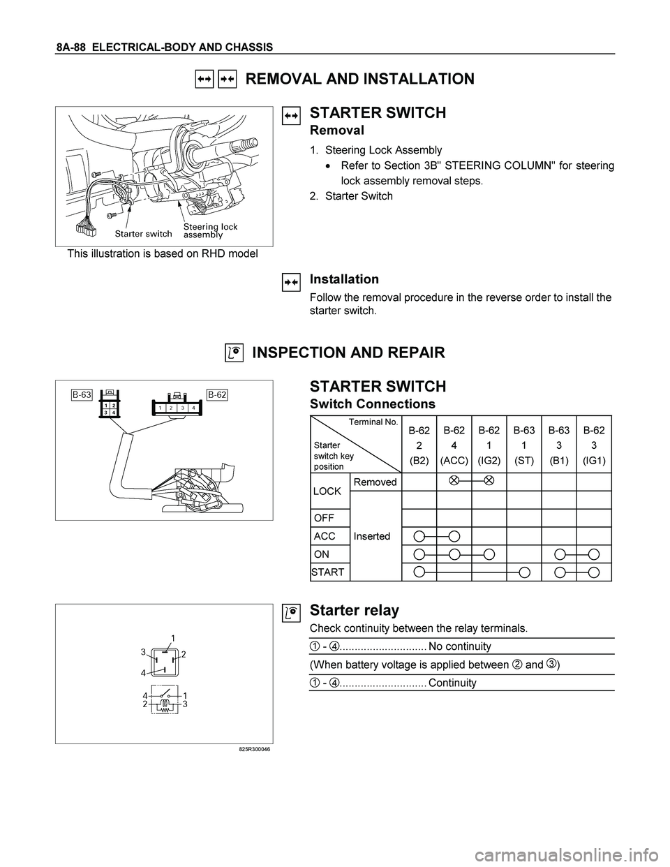
8A-88 ELECTRICAL-BODY AND CHASSIS
REMOVAL AND INSTALLATION
This illustration is based on RHD model
STARTER SWITCH
Removal
1. Steering Lock Assembly
� Refer to Section 3B" STEERING COLUMN" for steering
lock assembly removal steps.
2. Starter Switch
Installation
Follow the removal procedure in the reverse order to install the
starter switch.
INSPECTION AND REPAIR
STARTER SWITCH
Switch Connections
Terminal No.
Starter
switch key
position B-62
2
(B2)B-62
4
(ACC)B-62
1
(IG2) B-63
1
(ST) B-63
3
(B1)B-62
3
(IG1)
Removed
OFF
ACC Inserted
ON
START
LOCK
825R300046
Starter relay
Check continuity between the relay terminals.
1 - 4............................. No continuity
(When battery voltage is applied between 2 and 3)
1 - 4............................. Continuity
Page 778 of 4264
8A-120 ELECTRICAL-BODY AND CHASSIS
TROUBLE SHOOTING
HEADLIGHT
1. Both the headlights (high and low beam) do not light
Checkpoint Trouble Cause Countermeasure
Repair the wiring
Poor ground point contact
NG
Repair open circuit or
connector contact
Repair open circuit
Repair or replace the
combination switch
Voltage between 1
B-60 -
ground
Open circuit between lighting
relay and lighting switch
Open circuit between battery
positive terminal and lighting
relay
Combination switch continuity
Poor switch contact or sw
faulty
Voltage between
5
X-12 - ground and
2
X-12 - ground
Reinstall or replace the
lighting relay
Lighting relay
Poor relay contact or relay
faulty
NG NG NG NG OK
OK
OK OK
Ground point contact (C-36)
Repair open circuit
Wiring continuity between
B-60 - C-36
Open circuit
NG OK
Page 779 of 4264

ELECTRICAL-BODY AND CHASSIS 8A-121
2. High or low beam does not light on both headlights
Checkpoint Trouble Cause Countermeasure
Repair or replace the
combination switch
Dimmer�passing switch
continuity
Poor switch contact or switch
faulty
NG
Repair open circuit or
connector contact
Voltage between
4
X-4 - ground and
4
B-60 - ground
Open circuit between
headlight and dimmer�passing
switch
NG OK
3. RH (or LH) high and low beam does not light
Replace the headlight bulb
Headlight connector continuity
Blown filament or air leakage
NG
Repair or replace the wire
and/or connector
Wiring continuity between
connector 3
C-19 - fuse No.
EB-7 or 3
C-26 fuse No.
EB-8
Open circuit and/or poor
connector contact
NG OK
Reinstall or replace fuse No.
EB-7 or No. EB-8
Fuse No. EB-7 (10A) or
No. EB-8 (10A) (Relay and
fuse box)
(No. EB-7 RH, No. EB-8: LH)
Poor installation or blown fuse
NG
OK
4. High or low beam does not light on one headlight (RH or LH)
Replace the headlight
assemblyHeadlight connector continuityBlown filament NG
Repair open circuit or
connector contactWiring continuity between
headlight and dimmer�passing
switchOpen circuit between
headlight and dimmer�passing
switch NG OK
Page 780 of 4264

8A-122 ELECTRICAL-BODY AND CHASSIS
5. Headlight does not go out
Checkpoint Trouble Cause Countermeasure
Replace the lighting relay
Lighting relay continuity
between connector 1
X-12
- 2
X-12 (Should be no
continuity)
Relay point fused
NG
Replay the combination switch
Lighting switch continuity
between connector 3
B-60
-1
B-60 when switch is
OFF(Should be no continuity)
point fused or faulty
NG
OK OK
Repair or replace the
combination switch
Dimmer�passing switch con-
tinuity between connector
3
B-60 - 1 B-60 when switch
is not operating
(Should be no continuity)
Switch point fused or faulty
NG
Repair short circuit
between 4
X-12 - 3 B-60
and 4
X-1 - 2 B-60
Check if headlight goes out
when connector
C-30 is
disconnected
Short circuit
NG OK
6. Insufficient headlight brightness
Replace the headlight bulb
Headlight bulb
Bulb filament faulty
NG
Repair the wiring
Dimmer�passing switch
Wire continuity between con-
nector 1
B-60 - C-36
Poor ground point contact
NG OK
Clean the light lens
Headlight lens
Lens dirty
NG
OK
Page 781 of 4264
ELECTRICAL-BODY AND CHASSIS 8A-123
7. Passing light does not function when dimmer switch is operated
Checkpoint Trouble Cause Countermeasure
Repair or replace the dimmer
switch
Dimmer switch
Poor switch point contact
NG
Repair open circuit between
4
X-12 - 3 B-60
Voltage between
3
B-60 - ground (Should
be battery voltage present)
Open circuit
NG OK
8. Headlight beam does not change when dimmer switch is operated
Repair or replace the dimmer
switchDimmer switchLoose beam lever or foreign
material in switch NG


 do not light
Checkpoint Trouble Cause Countermeasure
Repair the wiring
Poor")
