Page 644 of 4264
7C-42 CLUTCH
TROUBLESHOOTING
Refer to this Section to quickly diagnose and repair clutch problems.
Each troubleshooting chart has three headings arranged from left to right.
(1) checkpoint (2) Trouble Cause (3) Countermeasure
This Section is divided into five sub-sections:
1. Clutch Slippage
2. Clutch Does Not Release Properly
3. Clutch Shudder
4. Clutch Noise
1) Clutch pedal Depressed (Clutch Disengaged)
2) Clutch pedal Not Depressed (Clutch Engaged)
5. Oil Leakage
Page 657 of 4264
WORKSHOP MANUAL
TF SERIES
ELECTRICAL-BODY AND CHASSIS
SECTION 8
Page 659 of 4264

ELECTRICAL-BODY AND CHASSIS 8A-1
SECTION 8A
ELECTRICAL-BODY AND CHASSIS
TABLE OF CONTENTS
PAGE
General Information ........................................................................................................ 8A- 4
Notes for Working on Electrical Items .......................................................................... 8A- 5
Symbols and Abbreviations ........................................................................................... 8A- 11
Symbols ...................................................................................................................... 8A- 11
Abbreviations ............................................................................................................. 8A- 12
Parts for Electrical Circuit .............................................................................................. 8A- 13
Wiring .......................................................................................................................... 8A- 13
Fuse ............................................................................................................................. 8A- 15
Fusible Link ................................................................................................................ 8A- 15
Relay ............................................................................................................................ 8A- 16
Diode ........................................................................................................................... 8A- 17
Connector ................................................................................................................... 8A- 18
Battery ......................................................................................................................... 8A- 19
Reading the Circuit Diagram .......................................................................................... 8A- 22
Parts Location ............................................................................................................ 8A- 22
Circuit Diagram ........................................................................................................... 8A- 23
Connector List ............................................................................................................. 8A- 23
Main Data and Specifications ........................................................................................ 8A- 24
Bulb Specifications .................................................................................................... 8A- 24
Relay and Fuse ................................................................................................................ 8A- 26
Relay and Fuse Box Location ................................................................................... 8A- 26
Relay Location ............................................................................................................ 8A- 28
Page 667 of 4264

ELECTRICAL-BODY AND CHASSIS 8A-9
SPLICING WIRE
Open the Harness
If the harness is taped, remove the tape.
To avoid wire insulation damage, use a sewing "seam ripper"
(available from sewing supply stores) to cut open the harness.
If the harness has a black plastic conduit, simply pull out the
desired wire.
Cut the wire
Begin by cutting as little wire off the harness as possible.
You may need the extra length of wire later if you decide to cut
more wire off to change the location of a splice.
You may have to adjust splice locations to make certain that
each splice is at least 1-1/2" (40 mm) away from other splices,
harness branches, or connectors.
Strip the insulation
When replacing a wire, use a wire of the same size as the
original wire.
Check the stripped wire for nicks or cut strands.
If the wire is damaged, repeat the procedure on a new section
of wire.
The two stripped wire ends should be equal in length.
Crimp the Wires
Select the proper clip to secure the splice.
To determine the proper clip size for the wire being spliced,
follow the directions included with your clips.
Select the correct anvil on the crimper.
(On most crimpers your choice is limited to either a small or
large anvil.)
Overlap the two stripped wire ends and hold them between
your thumb and forefinger.
Then, enter the splice clip under the stripped wires and hold it
in place.
� Open the crimping tool to its full width and rest one handle
on a firm flat surface.
� Center the back of the splice clip on the proper anvil and
close the crimping tool to the point where the back of the
splice clip touches the wings of the clip.
� Make sure that the clip and wires are still in the correc
t
position. Then, apply pressure until the crimping tool closes.
Before crimping the ends of the clip, be sure that:
� The wires extend beyond the clip in each direction.
� No strands of wire are cut loose.
� No insulation is caught under the clip.
Crimp the splice again, once on each end.
Do not let the crimping tool extend beyond the edge of the clip
or you may damage or nick the wires.
Page 672 of 4264
8A-14 ELECTRICAL-BODY AND CHASSIS
Distinction of Circuit by Wire Base Color
Base color Circuits Base color Circuits
B Starter circuit and grounding circuit Y Instrument circuit
W Charging circuit L, O, BR,
R Lighting circuit LG, GR, Other circuits
G Signal circuit P, LB, V
Wire Size
Wire size is specified with the metric gauge system.
The metric gauge system gives the wire size in cross sectional
area measured in square millimeters.
Wire Size Specifications
Normal size Cross sectional area
(mm2) Outside diameter
(mm) Allowable current
(A)
0.3 0.372 1.8 9
0.5 0.563 2.0 12
0.85 0.885 2.2 16
1.25 1.287 2.5 21
2 2.091 2.9 28
3 3.296 3.6 37.5
5 5.227 4.4 53
8 7.952 5.5 67
15 13.36 7.0 75
20 20.61 8.2 97
Page 676 of 4264
8A-18 ELECTRICAL-BODY AND CHASSIS
CONNECTOR
The connector pin shape determines whether the connector is
male or female.
The connector housing configuration does not determine
whether a connector is male or female.
The symbol illustrated in the figure is used as connector in the
circuit this section.
Connector is identified with a number.
The applicable terminal number is shown for each connector.
Connector terminal numbers are clearly shown.
Male side connector terminal numbers are in sequence from
upper right to lower left.
Female side connector terminal numbers are in sequence from
upper left to lower right.
NOTE:
For those connectors on which specific terminal numbers
on symbols are shown, the terminal numbers or symbols
are used in the circuit diagram, irrespective of the above
rule.
Page 746 of 4264
8A-88 ELECTRICAL-BODY AND CHASSIS
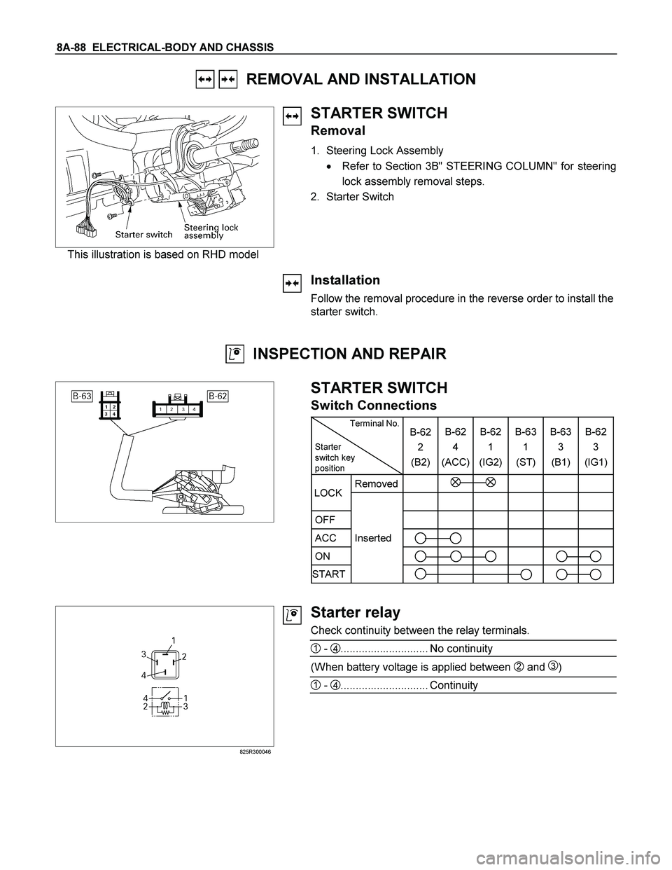
REMOVAL AND INSTALLATION
This illustration is based on RHD model
STARTER SWITCH
Removal
1. Steering Lock Assembly
� Refer to Section 3B" STEERING COLUMN" for steering
lock assembly removal steps.
2. Starter Switch
Installation
Follow the removal procedure in the reverse order to install the
starter switch.
INSPECTION AND REPAIR
STARTER SWITCH
Switch Connections
Terminal No.
Starter
switch key
position B-62
2
(B2)B-62
4
(ACC)B-62
1
(IG2) B-63
1
(ST) B-63
3
(B1)B-62
3
(IG1)
Removed
OFF
ACC Inserted
ON
START
LOCK
825R300046
Starter relay
Check continuity between the relay terminals.
1 - 4............................. No continuity
(When battery voltage is applied between 2 and 3)
1 - 4............................. Continuity
Page 763 of 4264
ELECTRICAL-BODY AND CHASSIS 8A-105
REMOVAL AND INSTALLATION
ECM (ENGINE CONTROL MODULE):
C24SE
Removal
1. Lift both the ECM harness connector locking levers and
remove the two harness connectors form the ECM.
2. Remove the four socket head screws securing the ECM to
the mounting bracket.
3. Remove the ECM from the engine compartment
.
4. Pull out the ECM.
5. Disconnect both red and tan connectors.
Refer to the Section 6E-ENGINE of this Manual.
IMPORTANT: The replacement ECM must be programmed.
“SPS (Service Programming System) and immobiliser
programming (if equipped) is/are necessary”
Installation
Follow the removal procedure in the reverse order to install the
ECM.
Pay close attention to the important points mentioned in the
following paragraphs.
Connector
Be absolutely sure that ECM is securely connected.
This will prevent a poor contact and open circuit.
 checkpoint (2)")


:
C24SE
Removal
1. Lift both the ECM harness connector locking levers and
remove the two harness")