Page 835 of 4264

ELECTRICAL-BODY AND CHASSIS 8A-177
REAR COMBINATION LIGHT
Back Up Light
Removal
1. Open the rear gate.
2. Remove the screws.
3. Remove the rear combination light assembly.
4. Turn the bulb
3 counterclockwise to remove it.
Installation
Follow the removal procedure in the reverse order to install the
rear combination light.
Pay close attention to the important points mentioned in the
following paragraphs.
Bulbs
Be absolutely sure that each bulb is correctly installed.
This will prevent a poor contact and an open circuit.
This illustration is based on RHD model
HAZARD WARNING FLASHER SWITCH
Removal
1. Disconnect the battery ground cable.
2. Instrument Panel Cluster Assembly
� Refer to Section 10 “BODY” for instrument panel cluste
r
assembly removal steps.
3. Hazard Warning Switch
� Disconnect the switch connector.
� To remove the switch, push the lock from the back side
of the cluster assembly.
Installation
To install, follow the removal procedure in the reverse order.
Connector
Be absolutely sure that the hazard warning flasher switch
connector is securely connected.
This will prevent a poor contact and an open circuit.
Page 837 of 4264
ELECTRICAL-BODY AND CHASSIS 8A-179
HORN SWITCH
Removal
1. Disconnect the battery ground cable.
2. Disable the SRS (Refer to “Disabling the SRS”in this
section).
3. Check the both side hole of the steering cover.
4. Check the position of the pins in a hole. Push the pin in the
direction of an arrow.
5. Push the four pins at �5�6 mm bar.
6. Cancel the lock four pins.
7. Disconnect the SRS air bag connector and horn lead
connector located behind the air bag assembly and remove
the air bag assembly.
Installation
1. Connect the SRS bag connector and horn lead connector.
2.
Align the each snap stud of driver air bag to the hole of
steering wheel.
Page 838 of 4264
8A-180 ELECTRICAL-BODY AND CHASSIS
3. Push the SRS air bag area1 and area2. At that time confirm
the audible noise of each stud.
4. Enable the SRS (Refer to “Enabling the SRS”in this
section).
INSPECTION AND REPAIR
Switch side Harness side
B-60 B-60
TURN SIGNAL SWITCH
Lighting Switch Connections
Terminal No.
SW position 5 6 7
Left
Neutral
Right
Turning
direction
Switch side
B-16
HAZARD WARNING FLASHER SWITCH
Hazard Warning Flasher Switch Connections
Terminal
No.
SW position
4
6
5
3
2
1
7
8
ON
OFF
Page 865 of 4264
ELECTRICAL-BODY AND CHASSIS 8A-207
REMOVAL AND INSTALLATION
WIPER AND WASHER SWITCH
Removal
Refer to the removal steps of the LIGHTING SWITCH
(COMBINATION SWITCH) in “ LIGHTING “ of this section.
Installation
Follow the removal procedure in the reverse order to install the
wiper and washer switch.
This illustration is based on RHD model
Pay close attention to the important points mentioned in the
following paragraphs.
Connector
Be absolutely sure that the wiper and washer switch connector
is securely connected.
This will prevent a poor contact and an open circuit.
Page 919 of 4264

ELECTRICAL-BODY AND CHASSIS 8A-261
2. Even when the parking brake lever is pulled, the indicator light does not go off
Checkpoint Trouble Cause Countermeasure
Adjust the SW. installation
position or replace the parking
brake SW. Incorrect the parking brake
SW. adjustment or brake SW.
faulty
NG Thermo unit malfunction
Replace the brake fluid level
SW., or vacuum SW., or
repair a short circuit between
the parking brake SW.
connector 1
C-39
(Lever: 1
R-4) and 9 B-23
or the brake fluid level SW.
connector 2
C-37 and 9
B-23, (or the vacuum SW.
connector 1
C-38 and 9
B-23 : 4JH1-TC ONLY)
Check to see if the indicator
light goes off when the parking
brake SW. connector 1
C-39
(Lever: 1
R-4) is
di t d
Brake fluid level SW. or
vacuum SW. faulty or short
circuit
NG OK
Parking brake SW. installation
position and function
3. Oil pressure warning light does not go off while engine is running
Refer to ENGINE Section
Refer to ENGINE Section
NG Thermo unit malfunction
Repair a short circuit between
1
E-1 and 3 B-24
Check to see the warning light
goes off when the oil pressure
SW. connector
1
E-1 is disconnected
Short circuit
Replace the oil pressure unit
(or the oil pressure SW.)
Continuity between the oil
pressure SW. connector
1
E-1 and the body ground
when the engine is operating
Oil pressure unit (or oil
pressure SW) faulty
NG NG OK
OK
Engine oil pressure
Page 920 of 4264
8A-262 ELECTRICAL-BODY AND CHASSIS
REMOVAL AND INSTALLATION
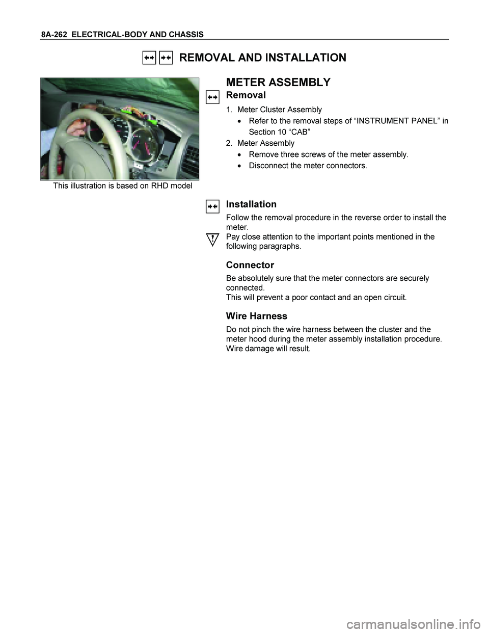
This illustration is based on RHD model
METER ASSEMBLY
Removal
1. Meter Cluster Assembly
� Refer to the removal steps of “INSTRUMENT PANEL” in
Section 10 “CAB”
2. Meter Assembly
� Remove three screws of the meter assembly.
� Disconnect the meter connectors.
Installation
Follow the removal procedure in the reverse order to install the
meter.
Pay close attention to the important points mentioned in the
following paragraphs.
Connector
Be absolutely sure that the meter connectors are securely
connected.
This will prevent a poor contact and an open circuit.
Wire Harness
Do not pinch the wire harness between the cluster and the
meter hood during the meter assembly installation procedure.
Wire damage will result.
Page 963 of 4264
ELECTRICAL-BODY AND CHASSIS 8A-305
REMOVAL AND INSTALLATION
This photo is based on 2 doors
DRIVER SEAT SIDE POWER WINDOW &
DOOR LOCK SWITCH
Removal
1. Disconnect the battery ground cable.
2. Removes the screw in pull cup with the screwdriver.
3. Remove the switch bezel by pushing the spring with the tip
of a screwdriver.
4. Disconnect the connector.
ATTENTION:
When removing a switch bezel lift from the front in the
bezel.
It follows the front with the screwdriver.
The clip has broken when lifting from the rear in the bezel.
Installation
To install, follow the removal steps in the reverse order.
DRIVER’S SIDE DOOR LOCK SWITCH
Removal
1. Door Lock ASM
� Refer to the removal steps of the DOORS in section 10
“BODY”.
2. Door Lock Switch
Installation
To install, follow the removal steps in the reverse order.
Page 964 of 4264
8A-306 ELECTRICAL-BODY AND CHASSIS
FRT PASSENGER’S SIDE DOOR LOCK
ACTUATOR
Removal
1. Door Lock ASM
� Refer to the removal steps of the DOORS in Section 10
“BODY”.
2. Door Lock Actuator
� Remover the actuator fixing bolts.
� Disconnect the door lock link rod.
� Disconnect the actuator connector.
Installation
To install, follow the removal steps in the reverse order.
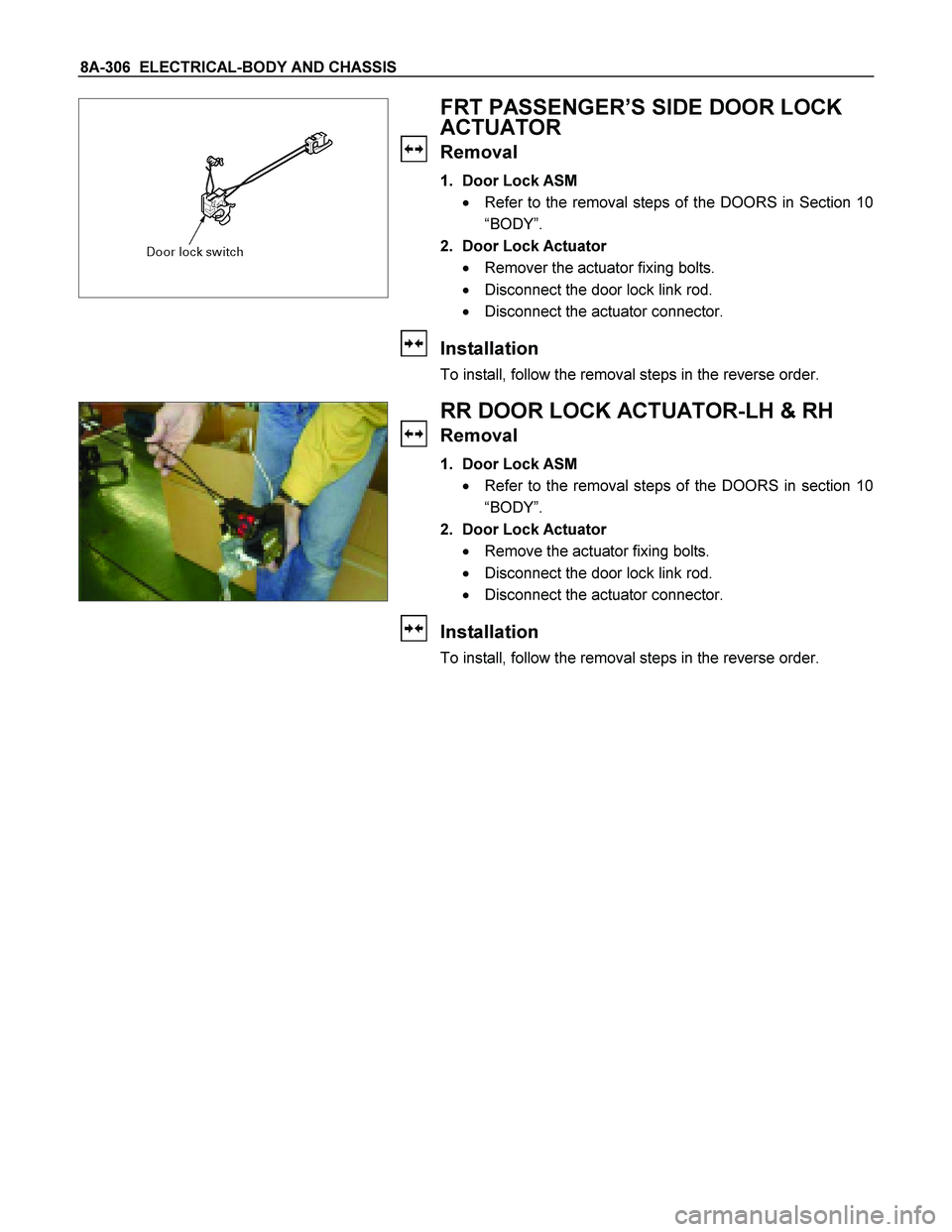
RR DOOR LOCK ACTUATOR-LH & RH
Removal
1. Door Lock ASM
� Refer to the removal steps of the DOORS in section 10
“BODY”.
2. Door Lock Actuator
� Remove the actuator fixing bolts.
� Disconnect the door lock link rod.
� Disconnect the actuator connector.
Installation
To install, follow the removal steps in the reverse order.
.
3. Check the both side")

 in “ LIGHTING “ of")