Page 1303 of 4264
 4JA1TC 4JH1TC
Injection pump type
Bosch distributor
VE type Bosch distributor VP44 type
Governor type Mech")
FUEL SYSTEM 6C – 3
MAIN DATA AND SPECIFICATIONS
Description Item
4JA1T (L) 4JA1TC 4JH1TC
Injection pump type
Bosch distributor
VE type Bosch distributor VP44 type
Governor type Mechanical variable
(Half speed oil
pressure) Electrical controled
Timer type Oil pressure Electrical controled
Fuel feed pump type Vane with input shaft
Injection nozzle type Hole type
Number of injection nozzle orifices 5
Injection nozzle orifices
Inside diameter mm (in) 0.19 (0.0075) 0.17 (0.0067) 0.21 (0.0083)
19.1 (195) 19.0 (194) 19.5 (199) Injection nozzle designed operating
pressure MPa (kg/cm2) 1st
2nd 25.0 (255) 33.5 (328) 33.8 (331)
Main fuel filter type Disposable cartridge paper element
Precautions
When working on the fuel system, there are several things
to keep in mind:
Any time the fuel system is being worked on,
disconnect the negative battery cable except fo
r
those tests where battery voltage is required.
Always keep a dry chemical (Class B) fire
extinguisher near the work area.
Replace all pipes with the same pipe and fittings that
were removed.
Clean and inspect “O" rings. Replace if required.
Always relieve the line pressure before servicing any
fuel system components.
Do not attempt repairs on the fuel system until you
have read the instructions and checked the pictures
relating to that repair.
Adhere to all Notices and Cautions.
NOTE:
Injection nozzle adjustment is possible only on the 4JA1L
engine.
Page 1316 of 4264

6C – 16 FUEL SYSTEM
140R100037
2. For removal of the quick connector, hold the quick
connector in one hand, and pull out the connector with the
other hand while pressing the square relieve button of the
connector, as illustrated.
NOTE: Do not use tools of any kind. Only use bare hands
when disconnecting the connector. Use a lubricant (light oil)
and/or push and pull the connector until the pipe is
disconnected.
140R100028
Cover the connectors that was removed with a plastic bag,
to prevent dust or rain water from entering.
140R100036
Reuse of Quick–Connector
�
Replace the port and connector if scratch, dent or crack is
found.
� Remove any dirt build up on the port when installing the
connector. Replace the connector, if there is any forms o
f
rust, dent, scratch.
�
After cleaning the port, insert it straight into the connector
until it clicks. After it clicks, try pulling at 49N (5kgf) it out to
make sure that it is not drawn and is securely locked.
Assembling Advice
By applying engine oil or light oil to the pipe, port makes pipe
assembly easier. The pipe assembly should take place
immediately after applying oil (to prevent dust from sticking to
the pipe surface – which may decrease sealing ability).
Test/Inspection After Assembling
1. Reconnect the battery negative cable.
2. Start the engine and observe the engine idle speed. The
presence of dirt in the fuel system may affect the fuel
injection system.
3. Check for fuel leakage from the connector.
Page 1348 of 4264
6D – 10 ENGINE ELECTRICAL
RTW46DSH000101
Important Operations
1. Vacuum Pump
1. Loosen the vacuum pump fixing screws.
2. Support the vacuum pump O-ring.
3. Carefully remove the O-ring.
2. Cover
RTW46DSH000201
3. Through Bolt
1. Remove the M5 through bolt.
2. Separate the front and rear sides of the vacuum pump.
3. Insert the tips of 2 ordinary screwdrivers into the space
between the front cover and the stator core. Remove
the front cover and rotor together with the rear cover
and stator.
If removal is difficult, push the rear cover to the side and
lightly tap the end of the shaft with a plastic hammer to
loosen it.
� The front cover oil seal must be replaced with a new
one when the front cover is removed.
� Take care not to damage the stator core with the
screwdriver tips.
RTW46DSH000601
RTW46DSH002101
4. Pulley
1. Carefully clamp the rotor assembly in a vise.
2. Loosen the pulley nut.
3. Remove the pulley and the front cover from the rotor.
Page 1349 of 4264
ENGINE ELECTRICAL 6D – 11
RTW46DSH000301
7. Rotor Assembly
1. Remove the rotor from front cover assembly.
Remove the front cover stator and rectifier.
RTW46DSH000701
8. Front Cover Assembly
1. Remove the front cover bearing retainer screws.
2. Remove the bearing.
RTW46DSH000801
9. Rear rotor bearing
� Re-use improper parts.
10. Rectifier
1. Disconnect the stator coil leads between each rectifier
by melting the solder connection.
Hold the lead wire between the solder and the rectifier
with a pair of long nose pliers.
This will prevent heat transfer and resultant damage to
the rectifier.
RTW46DSH000401
Page 1350 of 4264
6D – 12 ENGINE ELECTRICAL
INSPECTION AND REPAIR
Make the necessary adjustments, repairs, and part replacement if excessive wear or damage is discovered during
inspection.
ROTOR ASSEMBLY
1. Inspect the slip ring faces for dirt and pitting. Wipe away any dirt with a clean cloth soaked in
alcohol.
2. Measure the slip ring diameter.
Slip Ring Diameter mm (in)
Standard Limit
RTW06DSH000101
31.6 (1.245) 30.6 (1.183)
If the slip ring diameter is less than the specified limit, the
slip rings must be replaced.
3. Measure the rotor coil resistance.
Rotor Coil Resistance at 20 �C (68 �F) ohms
Standard 3.8
RTW46DSH001001
RTW46DSH001101
4. Check for continuity between the slip rings and the
rotor core or shaft.
If there is continuity, the entire rotor assmbly must be
replaced.
Page 1351 of 4264
ENGINE ELECTRICAL 6D – 13
STATOR COIL ASSEMBLY
1. Check for continuity across the stator coils.
If there is no continuity, the stator coils must be
replaced.
Resistance Between The Terminal “N” and the Coil Ends
(Reference) ohms
Standard 0.1
066RY00022 2. Check for continuity between each stator coils and the
stator core.
If there is continuity, the stator coils must be replaced.
066RY00023
RTW46DSH004801
BRUSH
Measure the length of the brush. If abrasion has reduced
the brush length to less than 6.5 mm, the brush must be
replaced with a new one.
A wear line is inscribed in the brush. If the line is not
visible, the brush must be replaced.
Brush Length (Reference) mm (in)
Standard Limit
25 (1.0) 6.5 (0.25)
RTW46DSH001201
Rectifier
Tester wire
E BAT
U, V, and WN ⊕ � U, V, and WN⊕ �
⊕ ----- Conductivity ⊕ ----- No
conductivity
�
No
conductivity -----
� Conductivity -----
Negative side diode check Positive side diode check
Page 1353 of 4264

ENGINE ELECTRICAL 6D – 15
Oil seal
The oil seal must be replaced with a new one whenever
the alternator is disassembled.
Oil Seal Replacement
1. Push the old oil seal from the rear bracket outside
holes.
2. Use the insertion tool to press the new oil seal into
place. Follow the procedure shown in Figures A, B, C
and D.
� Position the oil seal beneath the shaft and the
guide lip.
� Position the cradle against the rear cover bosses
(3 points) so that the E1 and E2 surfaces fit into
the cradle. Take care not to damage the E1 and
E2 surfaces.
� After completing the procedure, carefully check the
oil seal seating. Be absolutely sure that the seal is
evenly inserted (no warp) and level with the
surrounding surfaces.
Caution
�
�� � Be sure that no foreign material enters the space
between the oil seal and the rotor shaft surfaces
during the installation procedure.
�
�� � Take care not to damage the D surface.
�
�� � Under no circumstances may the original oil seal
be reused.
�
�� � The oil seal must be perfectly flat after being
pressed into place. If the oil seal is tilted, there will
be oil leakage.
RTW46DSF000101
Page 1357 of 4264
ENGINE ELECTRICAL 6D – 19
RTW46DSH000401
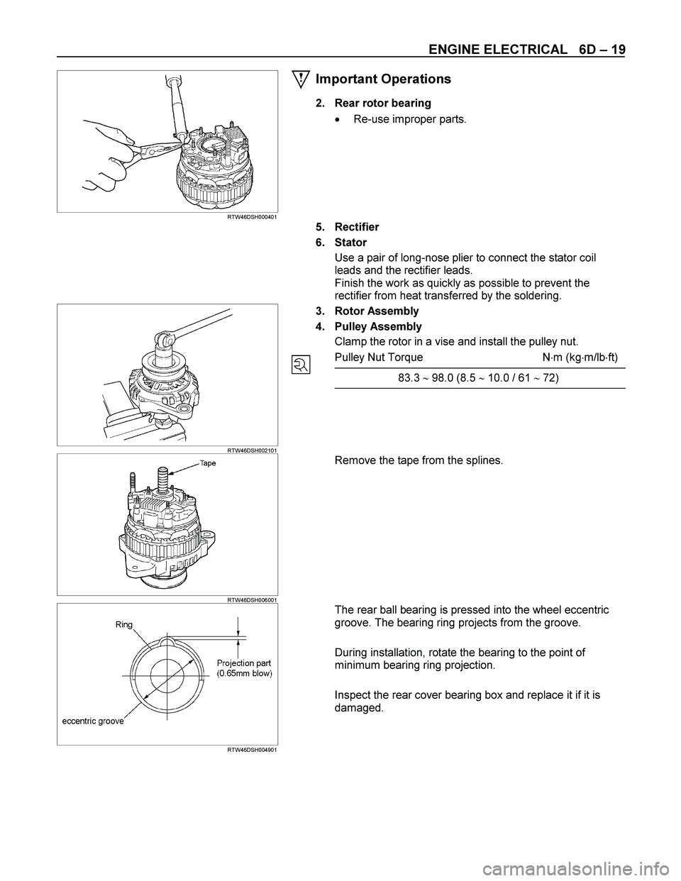
Important Operations
2. Rear rotor bearing
� Re-use improper parts.
5. Rectifier
6. Stator
Use a pair of long-nose plier to connect the stator coil
leads and the rectifier leads.
Finish the work as quickly as possible to prevent the
rectifier from heat transferred by the soldering.
RTW46DSH002101
3. Rotor Assembly
4. Pulley Assembly
Clamp the rotor in a vise and install the pulley nut.
Pulley Nut Torque N�m (kg�m/lb�ft)
83.3 � 98.0 (8.5 � 10.0 / 61 � 72)
RTW46DSH006001
Remove the tape from the splines.
RTW46DSH004901
The rear ball bearing is pressed into the wheel eccentric
groove. The bearing ring projects from the groove.
During installation, rotate the bearing to the point of
minimum bearing ring projection.
Inspect the rear cover bearing box and replace it if it is
damaged.