Page 4232 of 4264
7A4-58 UNIT REPAIR (JR405E)
Free length = 22.3 mm (0.878 in)
Linear diameter = 1.1 mm (0.043 in)
12CASE-AY06
Reassembly steps
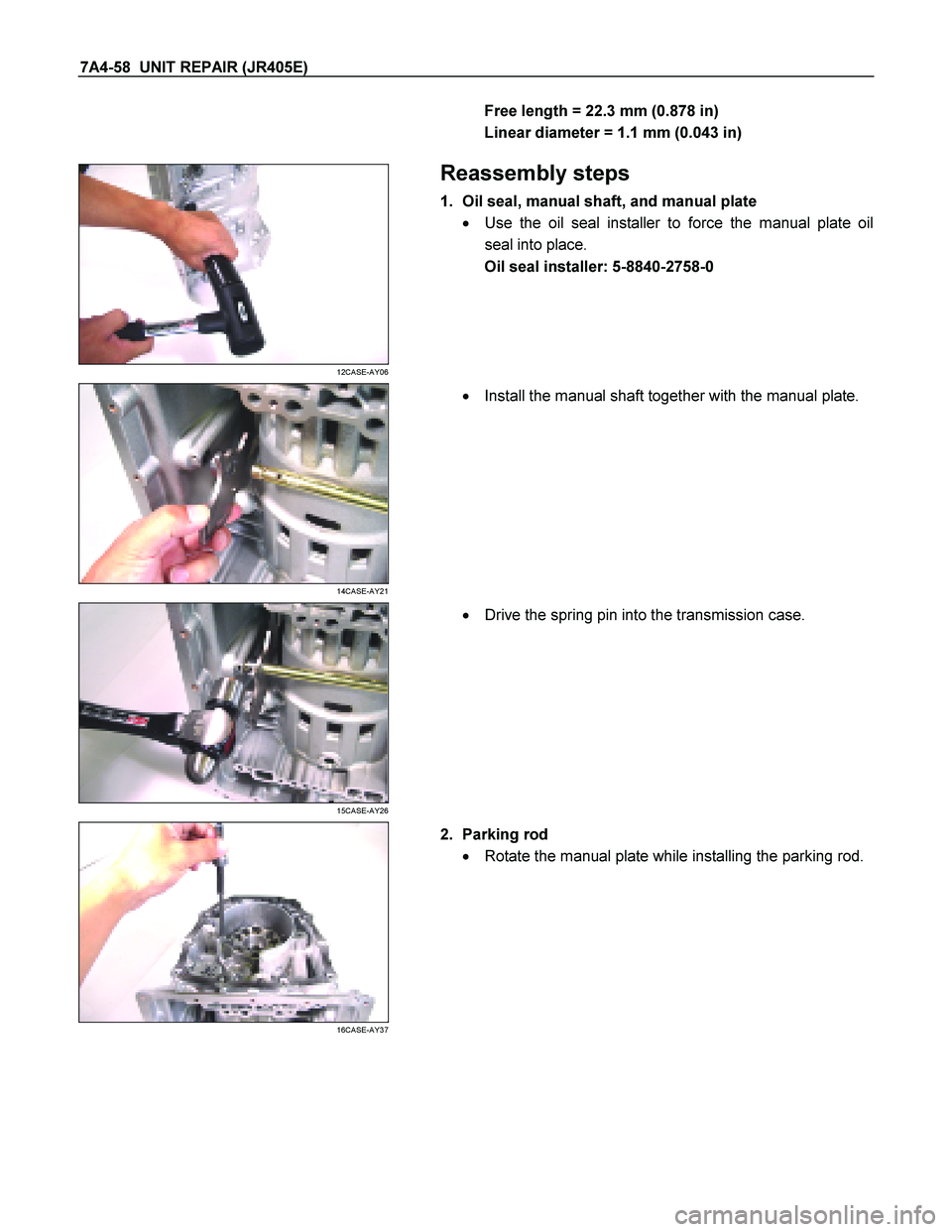
1. Oil seal, manual shaft, and manual plate
� Use the oil seal installer to force the manual plate oil
seal into place.
Oil seal installer: 5-8840-2758-0
14CASE-AY21
�
Install the manual shaft together with the manual plate.
15CASE-AY26
�
Drive the spring pin into the transmission case.
16CASE-AY37
2. Parking rod
� Rotate the manual plate while installing the parking rod.
Page 4236 of 4264
7A4-62 UNIT REPAIR (JR405E)
RTW37AMF0001-X
36ASSY10
�
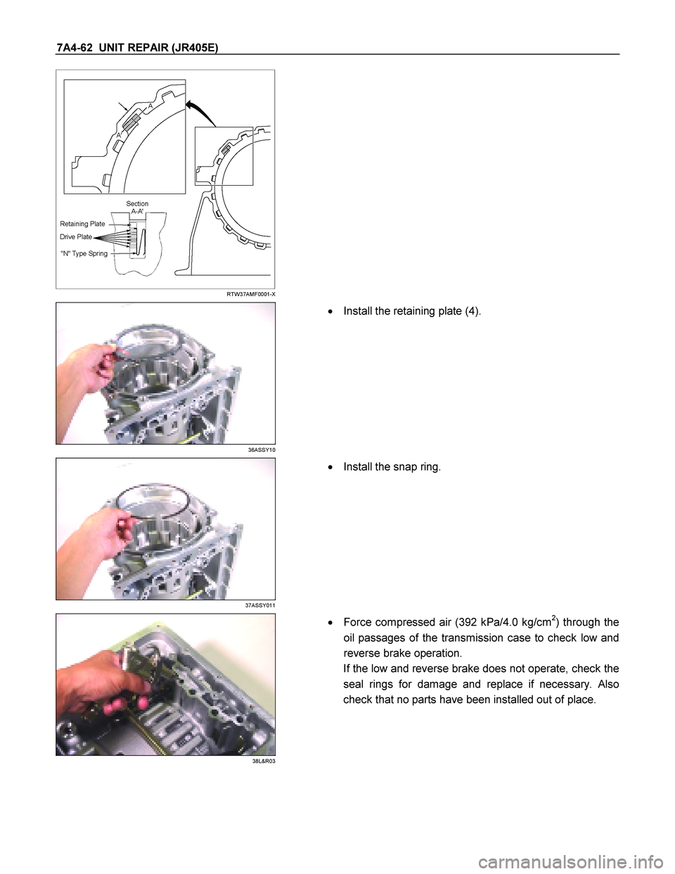
Install the retaining plate (4).
37ASSY011
�
Install the snap ring.
38L&R03
�
Force compressed air (392 kPa/4.0 kg/cm2) through the
oil passages of the transmission case to check low and
reverse brake operation.
If the low and reverse brake does not operate, check the
seal rings for damage and replace if necessary. Also
check that no parts have been installed out of place.
Page 4239 of 4264
 7A4-65
472-4B17
�
Install the spring compressor to the transmission case.
Spring compressor: 5-8840-2764-0
NOTE:
Be sure that the spring compressor is perfectl")
UNIT REPAIR (JR405E) 7A4-65
472-4B17
�
Install the spring compressor to the transmission case.
Spring compressor: 5-8840-2764-0
NOTE:
Be sure that the spring compressor is perfectly centered
(an off-center special tool will damage the return spring).
� Use the spring compressor to force the 2-4 brake
retainer.
482-4B18
NOTE:
To avoid damaging the return spring, apply as little force
as possible to the 2-4 brake retainer.
� Install the snap ring.
492-4B22
�
Force compressed air (392 kPa/4.0 kg/cm2) through the
oil passages of the transmission case to operate and
break-in the 2-4 brake.
502-4B19
�
Measure the clearance between the 2-4 brake retainer
and the retaining plate.
If the clearance is outside the specified range, replace
the existing brake retainer with a new one of the prope
r
size (thickness).
2 – 4 brake retainer and retaining plate clearance:
1.0~1.4 mm (0.039~0.055 in)
Available 2-4 brake retaining plate thicknesses
5.4 mm (0.213 in)
5.6 mm (0.220 in)
5.8 mm (0.228 in)
6.0 mm (0.236 in)
6.2 mm (0.244 in)
6.4 mm (0.252 in)
� Use the spring compressor to release the 2-4 brake.
Page 4244 of 4264

AUTOMATIC TRANSMISSION
REASSEMBLY
Assembly cautions
� Use your bare hands or vinyl gloves to reassemble the
transmission. Do not use ordinary work gloves (loosen")
7A4-70 UNIT REPAIR (JR405E)
AUTOMATIC TRANSMISSION
REASSEMBLY
Assembly cautions
� Use your bare hands or vinyl gloves to reassemble the
transmission. Do not use ordinary work gloves (loosen
threads from the gloves may fall into the transmission
and cause problems).
� Before installing the drive plates, immerse them in the
recommended automatic transmission fluid (BESCO
ATF II or ATF III). If the drive plate is new, it must be
immersed for at least two hours to ensure oil penetration
and saturation of the facing.
�
Apply ATF to all sliding and contact surfaces before
assembly. Also apply ATF to seal rings and O-rings.
Assemble the parts carefully to avoid damaging them.
� Replace any snap ring that appears worn, bent out o
f
shape, or otherwise damaged.
� If any part contacting the transmission case is damaged,
it must be replaced with a new part.
� Be careful not to damage the plates during reassembly
(oil leakage from the plate will result).
� If you are reusing a seal, remove the old adhesive agen
t
and clean the surface with cleaning oil before applying
the new adhesive agent.
� Wait at least two hours after installing the oil seals
before installing the plates.
� Do not replace O-rings, snap rings, bearings, and/o
r
bearing races with inferior substitutes.
Page 4249 of 4264
UNIT REPAIR (JR405E) 7A4-75
192-4B22
�
Force compressed air (392 kPa/4.0 kg/cm2) through the
transmission case oil passage to 2-4 brake operation.
If the 2-4 brake does not operate, the seal ring may be
damaged or the parts may have been installed in the
wrong order.
20ASSY037
9. Bearing race, front sun gear, and bearing
� Install the bearing race to the front sun gear.
NOTE:
Apply Vaseline to the bearing race and bearing to prevent
them from falling during the installation procedure.
21ASSY040
� Install the front sun gear to the transmission case.
22ASSY042
� Install the bearing to the front sun gear.
23ASSY045
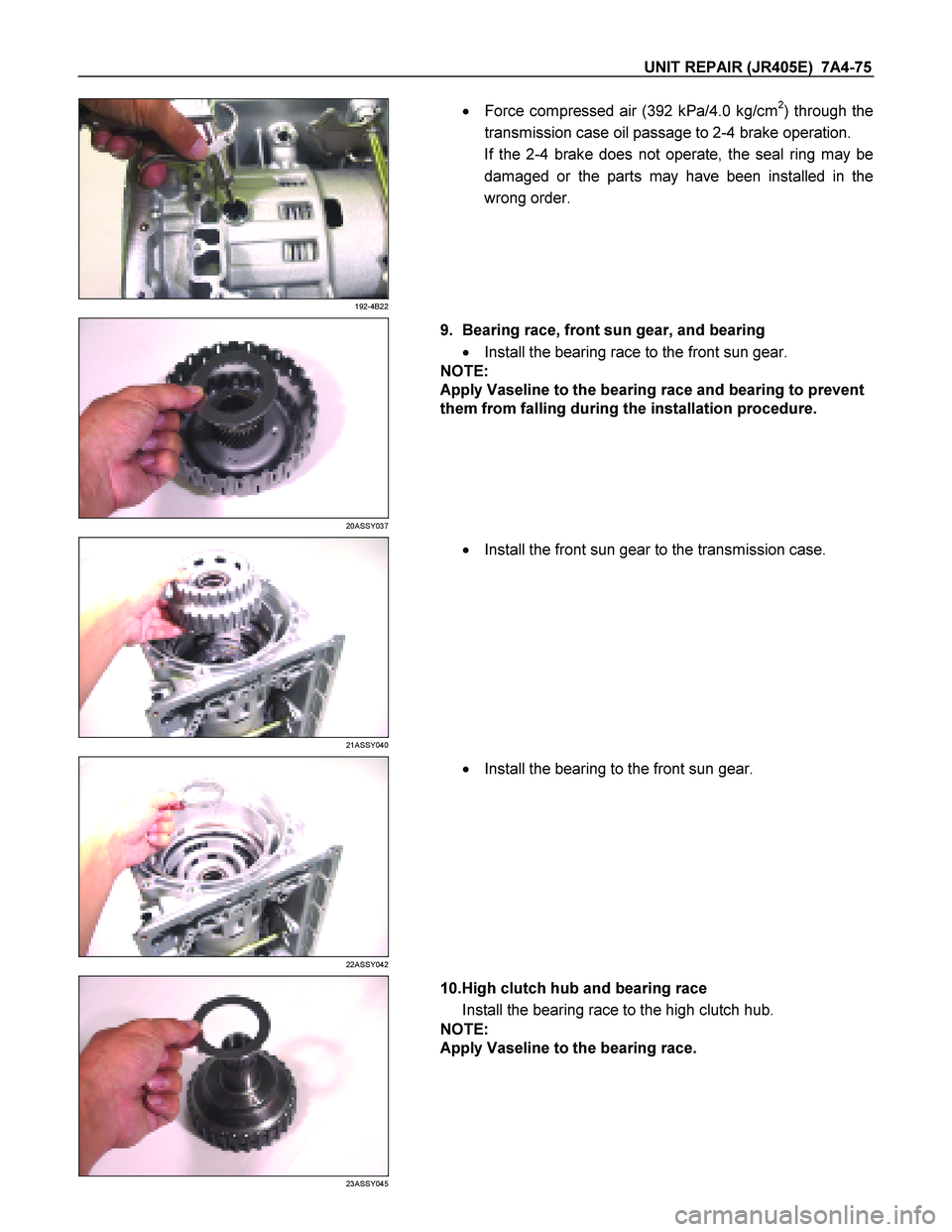
10.High clutch hub and bearing race
Install the bearing race to the high clutch hub.
NOTE:
Apply Vaseline to the bearing race.
Page 4250 of 4264
7A4-76 UNIT REPAIR (JR405E)
24ASSY047
�
Install the high clutch hub and the bearing race to the
transmission case.
25R&H42
11.Clutch pack (reverse and high clutch assembly)
� Install the bearing (with bearing race) to the clutch pack.
NOTE:
�
� �
�
The black side (bearing race) of the bearing must
contact the clutch pack.
�
� �
�
Apply Vaseline to the bearing.
26ASSY049
�
Install the clutch pack and bearing to the transmission
case.
27ASSY051
�
Install the bearing to the clutch pack.
NOTE:
Apply Vaseline to the bearing.
RTW47ASH000101
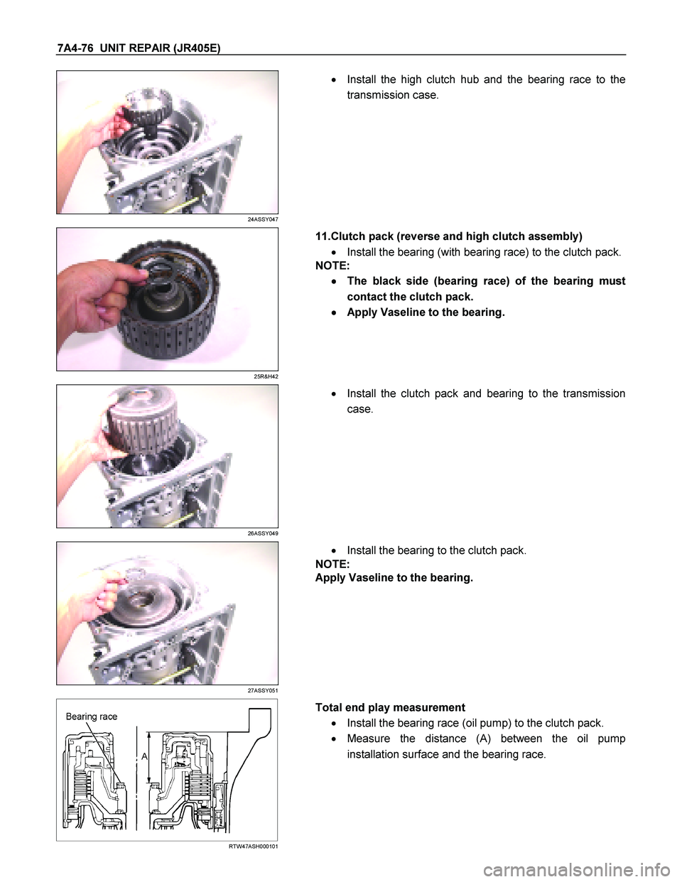
Total end play measurement
� Install the bearing race (oil pump) to the clutch pack.
� Measure the distance (A) between the oil pump
installation surface and the bearing race.
Page 4251 of 4264
UNIT REPAIR (JR405E) 7A4-77
RTW47ASH000201
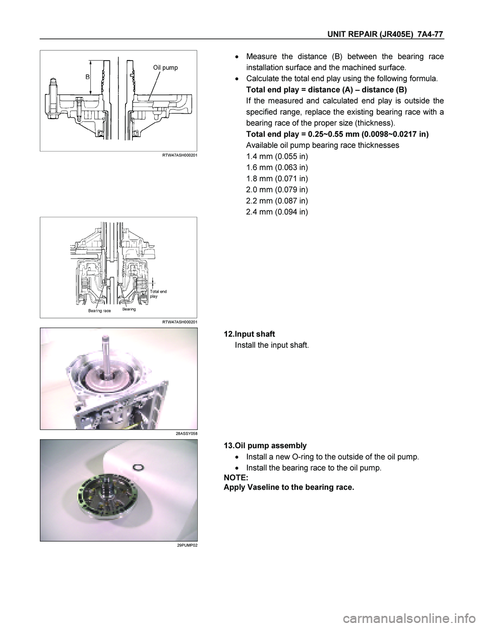
�
Measure the distance (B) between the bearing race
installation surface and the machined surface.
� Calculate the total end play using the following formula.
Total end play = distance (A) – distance (B)
If the measured and calculated end play is outside the
specified range, replace the existing bearing race with a
bearing race of the proper size (thickness).
Total end play = 0.25~0.55 mm (0.0098~0.0217 in)
Available oil pump bearing race thicknesses
1.4 mm (0.055 in)
1.6 mm (0.063 in)
1.8 mm (0.071 in)
2.0 mm (0.079 in)
2.2 mm (0.087 in)
2.4 mm (0.094 in)
RTW47ASH000201
28ASSY058
12.Input shaft
Install the input shaft.
29PUMP02
13.Oil pump assembly
� Install a new O-ring to the outside of the oil pump.
� Install the bearing race to the oil pump.
NOTE:
Apply Vaseline to the bearing race.
Page 4252 of 4264
7A4-78 UNIT REPAIR (JR405E)
30ASSY067
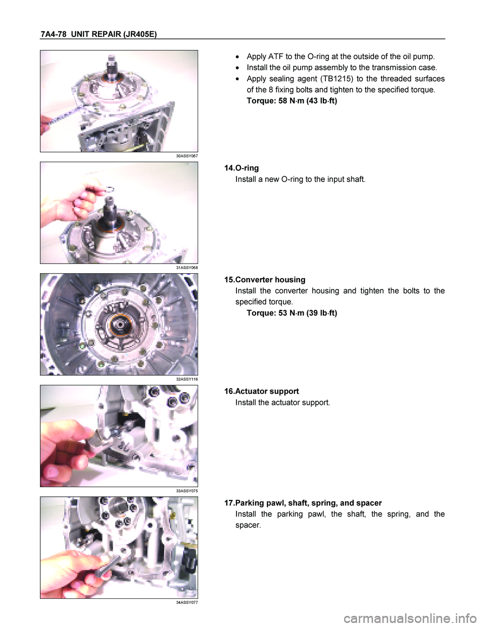
�
Apply ATF to the O-ring at the outside of the oil pump.
� Install the oil pump assembly to the transmission case.
�
Apply sealing agent (TB1215) to the threaded surfaces
of the 8 fixing bolts and tighten to the specified torque.
Torque: 58 N �
��
�
m (43 Ib �
��
�
ft)
31ASSY068
14.O-ring
Install a new O-ring to the input shaft.
32ASSY116
15.Converter housing
Install the converter housing and tighten the bolts to the
specified torque. Torque: 53 N �
��
�
m (39 Ib �
��
�
ft)
33ASSY075
16.Actuator support
Install the actuator support.
34ASSY077
17.Parking pawl, shaft, spring, and spacer
Install the parking pawl, the shaft, the spring, and the
spacer.