2004 ISUZU TF SERIES fuel type
[x] Cancel search: fuel typePage 2643 of 4264
ENGINE DRIVEABILITY AND EMISSIONS 6E–67
GENERAL SERVICE INFORMATION
Aftermarket Electrical and Vacuum
Equipment
Aftermarket (add-on) electrical and vacuum equipment
is defined as any equipment which connects to the
vehicle's electrical or vacuum systems that is installed
on a vehicle after it leaves the factory. No allowances
have been made in the vehicle design for this type of
equipment.
NOTE: No add-on vacuum equipment should be added
to this vehicle.
NOTE: Add-on electrical equipment must only be
connected to the vehicle's electrical system at the
battery (power and ground).
Add-on electrical equipment, even when installed to
these guidelines, may still cause the electric system to
malfunction. This may also include equipment not
connected to the vehicle electrical system such as
portable telephones and radios. Therefore, the first step
in diagnosing any electric problem is to eliminate all
aftermarket electrical equipment from the vehicle. After
this is done, if the problem still ex ists, it may be
diagnosed in the normal manner.
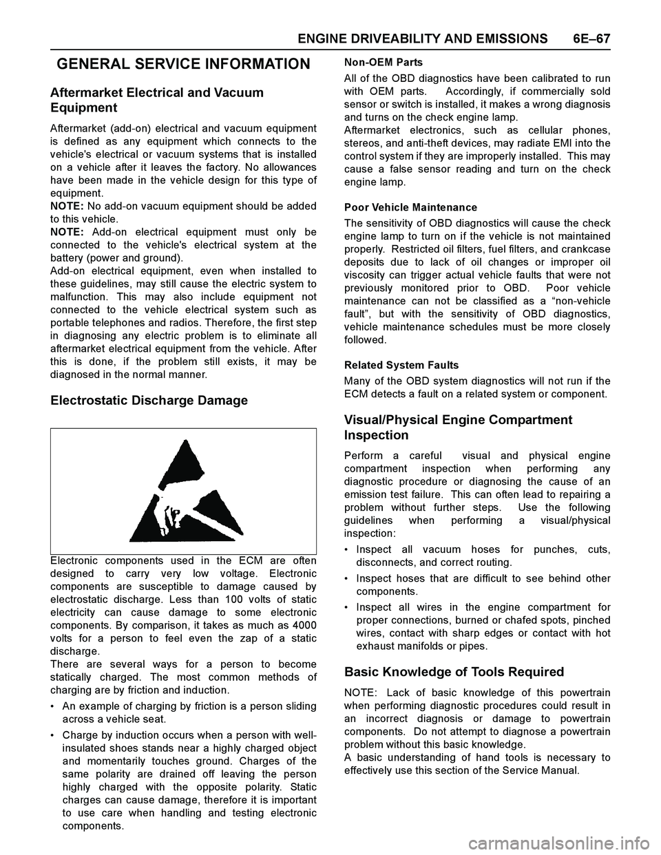
Electrostatic Discharge Damage
Electronic components used in the ECM are often
designed to carry very low voltage. Electronic
components are susceptible to damage caused by
electrostatic discharge. Less than 100 volts of static
electricity can cause damage to some electronic
components. By comparison, it takes as much as 4000
volts for a person to feel even the zap of a static
discharge.
There are several ways for a person to become
statically charged. The most common methods of
charging are by friction and induction.
An ex ample of charging by friction is a person sliding
across a vehicle seat.
Charge by induction occurs when a person with well-
insulated shoes stands near a highly charged object
and momentarily touches ground. Charges of the
same polarity are drained off leaving the person
highly charged with the opposite polarity. Static
charges can cause damage, therefore it is important
to use care when handling and testing electronic
components.Non-OEM Parts
All of the OBD diagnostics have been calibrated to run
with OEM parts. Accordingly, if commercially sold
sensor or switch is installed, it makes a wrong diagnosis
and turns on the check engine lamp.
Aftermarket electronics, such as cellular phones,
stereos, and anti-theft devices, may radiate EMI into the
control system if they are improperly installed. This may
cause a false sensor reading and turn on the check
engine lamp.
Poor Vehicle Maintenance
The sensitivity of OBD diagnostics will cause the check
engine lamp to turn on if the vehicle is not maintained
properly. Restricted oil filters, fuel filters, and crankcase
deposits due to lack of oil changes or improper oil
viscosity can trigger actual vehicle faults that were not
previously monitored prior to OBD. Poor vehicle
maintenance can not be classified as a “non-vehicle
fault”, but with the sensitivity of OBD diagnostics,
vehicle maintenance schedules must be more closely
follow ed.
Related System Faults
Many of the OBD system diagnostics will not run if the
ECM detects a fault on a related system or component.
Visual/Physical Engine Compartment
Inspection
Perform a careful visual and physical engine
compartment inspection when performing any
diagnostic procedure or diagnosing the cause of an
emission test failure. This can often lead to repairing a
problem without further steps. Use the following
guidelines when performing a visual/physical
inspection:
Inspect all vacuum hoses for punches, cuts,
disconnects, and correct routing.
Inspect hoses that are difficult to see behind other
components.
Inspect all wires in the engine compartment for
proper connections, burned or chafed spots, pinched
wires, contact with sharp edges or contact with hot
exhaust manifolds or pipes.
Basic Knowledge of Tools Required
NOTE: Lack of basic knowledge of this powertrain
when performing diagnostic procedures could result in
an incorrect diagnosis or damage to powertrain
components. Do not attempt to diagnose a powertrain
problem without this basic knowledge.
A basic understanding of hand tools is necessary to
effectively use this section of the Service Manual.
Page 2647 of 4264
ENGINE DRIVEABILITY AND EMISSIONS 6E–71
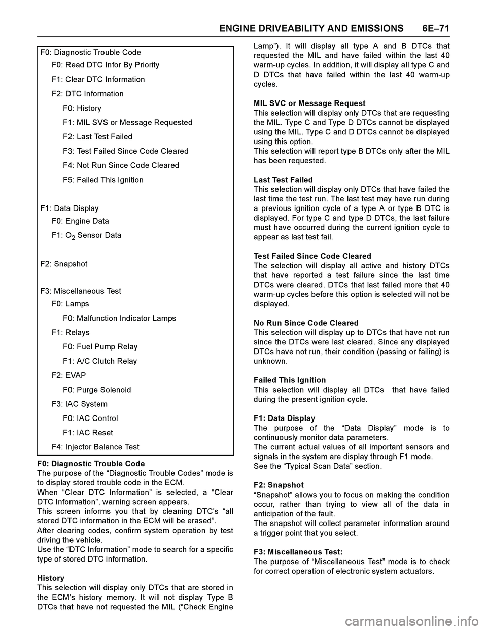
F0: Diagnostic Trouble Code
The purpose of the “Diagnostic Trouble Codes” mod e i s
to display stored trouble code in the ECM.
When “Clear DTC Information” is selected, a “Clear
DTC Information”, warning screen appears.
This screen informs you that by cleaning DTC's “all
stored DTC information in the ECM will be erased”.
After clearing codes, confirm system operation by test
driving the vehicle.
Use the “DTC Information” mode to search for a specific
type of stored DTC information.
History
This selection will display only DTCs that are stored in
the ECM's history memory. It will not display Type B
DTCs that have not requested the MIL (“Check EngineLamp”). It will display all type A and B DTCs that
requested the MIL and have failed within the last 40
warm-up cycles. In addition, it will display all type C and
D DTCs that have failed within the last 40 warm-up
cycles.
MIL SVC or Message Request
This selection will display only DTCs that are requesting
the MIL. Type C and Type D DTCs cannot be displayed
using the MIL. Type C and D DTCs cannot be displayed
using this option.
This selection will report type B DTCs only after the MIL
has been requested.
Last Test Failed
This selection will display only DTCs that have failed the
last time the test run. The last test may have run during
a previous ignition cycle of a type A or type B DTC is
displayed. For type C and type D DTCs, the last failure
must have occurred during the current ignition cycle to
appear as last test fail.
Test Failed Since Code Cleared
The selection will display all active and history DTCs
that have reported a test failure since the last time
DTCs were cleared. DTCs that last failed more that 40
warm-up cycles before this option is selected will not be
displayed.
No Run Since Code Cleared
This selection will display up to DTCs that have not run
since the DTCs were last cleared. Since any displayed
DTCs have not run, their condition (passing or failing) is
unknown.
Failed This Ignition
This selection will display all DTCs that have failed
during the present ignition cycle.
F1: Data Display
The purpose of the “Data Display” mode is to
continuously monitor data parameters.
The current actual values of all important sensors and
signals in the system are display through F1 mode.
See the “Typical Scan Data” section.
F2: Snapshot
“Snapshot” allows you to focus on making the condition
occur, rather than trying to view all of the data in
anticipation of the fault.
The snapshot will collect parameter information around
a trigger point that you select.
F3: Miscellaneous Test:
The purpose of “Miscellaneous Test” mode is to check
for correct operation of electronic system actuators.
F0: Diagnostic Trouble Code
F0: Read DTC Infor By Priority
F1: Clear DTC Information
F2: DTC Information
F0: History
F1: MIL SVS or Message Requested
F2: Last Test Failed
F3: Test Failed Since Code Cleared
F4: Not Run Since Code Cleared
F5: Failed This Ignition
F1: Data Display
F0: Engine Data
F1: O2 Sensor Data
F2: Snapshot
F3: Miscellaneous Test
F0: Lamps
F0: Malfunction Indicator Lamps
F1: Relays
F0: Fuel Pump Relay
F1: A/C Clutch Relay
F2: EVAP
F0: Purge Solenoid
F3: IAC System
F0: IAC Control
F1: IAC Reset
F4: Injector Balance Test
Page 2691 of 4264
ENGINE DRIVEABILITY AND EMISSIONS 6E–115
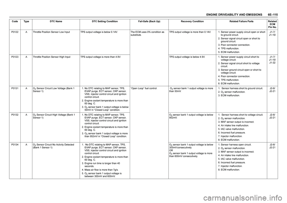
P0122 A Throttle Position Sensor Low Input TPS output voltage is below 0.14V. The ECM uses 0% condition as
substitute.TPS output voltage is more than 0.14V. 1. Sensor power supply circuit open or short
to ground circuit.
2. Sensor signal circuit open or short to
ground circuit.
3. Poor connector connection.
4. TPS malfunction.
5. ECM malfunction.J1-7/
J1-15/
P0123 A Throttle Position Sensor High Input TPS output voltage is more than 4.9V. TPS output voltage is below 4.9V. 1. Sensor power supply circuit short to
voltage circuit.
2. Sensor signal circuit short to voltage
circuit.
3. Sensor ground circuit open or short to
voltage circuit.
4. Poor connector connection.
5. TPS malfunction.
6. ECM malfunction.J1-7/
J1-15/
J1-32
P0131 A O
2 Sensor Circuit Low Voltage (Bank 1
Sensor 1)1. No DTC relating to MAP sensor, TPS,
EVAP purge, ECT sensor, CKP sensor,
VSS, injector control circuit and ignition
control circuit.
2. Engine coolant temperature is more than
60 deg. C.
3. O
2 sensor bank 1 output voltage is below
50mV in “Closed Loop” condition. “Open Loop” fuel control. O
2 sensor bank 1 output voltage is more
than 50mV.1. Sensor harness short to ground circuit.
2. O
2 sensor malfunction.
3. ECM malfunction.J2-6/
J2-21
P0132 A O
2 Sensor Circuit High Voltage (Bank 1
Sensor 1)1. No DTC relating to MAP sensor, TPS,
EVAP purge, ECT sensor, CKP sensor,
VSS, injector control circuit and ignition
control circuit.
2. Engine coolant temperature is more than
60 deg. C.
3. O
2 sensor bank 1 output voltage is more
than 952mV in “Closed Loop” condition. O
2 sensor bank 1 output voltage is below
952mV.1. Sensor harness short to voltage circuit.
2. O
2 sensor malfunction.
3. MAF sensor output is incorrect.
4. Air intake line malfunction.
5. IAC valve malfunction.
6. Incorrect fuel pressure.
7. Injector malfunction.
8. ECM malfunction.J2-6/
J2-21
P0134 A O
2 Sensor Circuit No Activity Detected
(Bank 1 Sensor 1)1. No DTC relating to MAP sensor, TPS,
EVAP purge, ECT sensor, CKP sensor,
VSS, injector control circuit and ignition
control circuit.
2. Engine coolant temperature is more than
60 deg. C.
3. Engine run time is longer than 40
seconds.
4. Mass air flow is more than 7g/s.
5. O
2 sensor bank 1 output voltage is
between 300mV and 600mV.O
2 sensor bank 1 output voltage is below
3 0 0 m V c o n s e c u t i v e l y .
O R
O2 sensor bank 1 output voltage is more
than 600mV consecutively.1. Sensor harness open circuit.
2. O
2 sensor malfunction.
3. MAF sensor output is incorrect.
4. Air intake line malfunction.
5. IAC valve malfunction.
6. Incorrect fuel pressure.
7. Injector malfunction.
8. ECM malfunction.J2-6/
J2-21 Code Type DTC Name DTC Setting Condition Fail-Safe (Back Up) Recovery Condition Related Failure Parts Related
ECM
Pin No.
Page 2694 of 4264
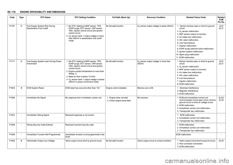
6E–118 ENGINE DRIVEABILITY AND EMISSIONSP1167 D Fuel Supply System Rich During
Deceleration Fuel Cutoff1. No DTC relating to MAP sensor, TPS,
EVAP purge, ECT sensor, CKP sensor,
VSS, injector control circuit and ignition
control circuit.
2. O
2 sensor bank 1 output voltage is more
than 550mV in deceleration fuel cutoff
mode.No fail-safe function. O
2 sensor output voltage is below 550mV. 1. Sensor harness open or short to ground
circuit.
2. O
2 sensor malfunction.
3. MAF sensor output is incorrect.
4. Air intake line malfunction.
5. IAC valve malfunction.
6. Low fuel pressure.
7. Injector malfunction.
8. EVAP purge solenoid valve malfunction.
9. Ignition system malfunction.
10. Spark plug malfunction.
11. ECM malfunction.J2-6/
J2-21
P1171 D Fuel Supply System Lean During Power
Enrichment 1. No DTC relating to MAP sensor, TPS,
EVAP purge, ECT sensor, CKP sensor,
VSS, injector control circuit and ignition
control circuit.
2. Engine coolant temperature is more than
60deg. C.
3. Mass air flow is below 13.5m/s.
4. O
2 sensor bank 1 output voltage is below
350mV in power enrichment mode. No fail-safe function. O
2 sensor output voltage is more than
350mV.1. Sensor harness open or short to ground
circuit.
2. O
2 sensor malfunction.
3. MAF sensor output is incorrect.
4. Air intake line malfunction.
5. IAC valve malfunction.
6. Low fuel pressure.
7. Injector malfunction.
8. ECM malfunction.J2-6/
J2-21
P1625 B ECM System Reset ECM reset has occurred other than “On”. Engine control disabled. Memory are is OK. 1. Electrical interference.
2. Magnetic interference.
3. ECM malfunction.-
P1626 - Immobilizer No Signal No response from immobilizer control unit. 1. Engine does not start.
2. Check engine lamp flash.No recovery. 1. ECM and immobilizer control unit
communication circuit open circuit, short to
ground circuit or short to voltage circuit.
2. ECM malfunction.
3. Immobilizer control unit malfunction.
4. Transponder key malfunction.J2-23/
J2-32
P1631 - Immobilizer Wrong Signal Received response is not correct.1. ECM malfunction.
2. Immobilizer control unit malfunction.
3. Transponder key malfunction.-
P1648 - Wrong Security Code Entered Received incorrect security code.1. ECM malfunction.
2. Immobilizer control unit malfunction.
3. Transponder key malfunction.-
P1649 - Immobilizer Function Not Programmed Immobilizer function is not programmed in the
ECM.ECM malfunction. -
P1693 B Tachometer Output Low Voltage Tacho output circuit short to ground circuit. No fail-safe function. Tacho output circuit is correct condition. 1. Tacho output circuit short to ground circuit.
2. Poor connector connection.
3. ECM malfunction.J2-25 Code Type DTC Name DTC Setting Condition Fail-Safe (Back Up) Recovery Condition Related Failure Parts Related
ECM
Pin No.
Page 2719 of 4264
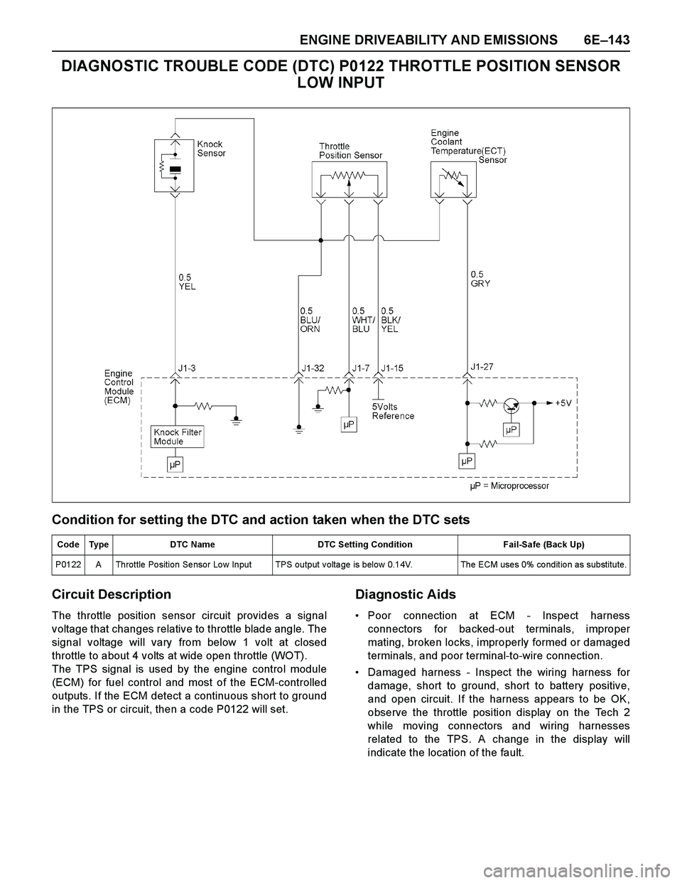
ENGINE DRIVEABILITY AND EMISSIONS 6E–143
DIAGNOSTIC TROUBLE CODE (DTC) P0122 THROTTLE POSITION SENSOR
LOW INPUT
Condition for setting the DTC and action taken when the DTC sets
Circuit Description
The throttle position sensor circuit provides a signal
voltage that changes relative to throttle blade angle. The
signal voltage will vary from below 1 volt at closed
throttle to about 4 volts at wide open throttle (WOT).
The TPS signal is used by the engine control module
(ECM) for fuel control and most of the ECM-controlled
outputs. If the ECM detect a continuous short to ground
in the TPS or circuit, then a code P0122 will set.
Diagnostic Aids
Poor connection at ECM - Inspect harness
connectors for backed-out terminals, improper
mating, broken locks, improperly formed or damaged
terminals, and poor terminal-to-wire connection.
Damaged harness - Inspect the wiring harness for
damage, short to ground, short to battery positive,
and open circuit. If the harness appears to be OK,
observe the throttle position display on the Tech 2
while moving connectors and wiring harnesses
related to the TPS. A change in the display will
indicate the location of the fault.
Code Type DTC Name DTC Setting Condition Fail-Safe (Back Up)
P0122 A Throttle Position Sensor Low Input TPS output voltage is below 0.14V. The ECM uses 0% condition as substitute.
Page 2723 of 4264
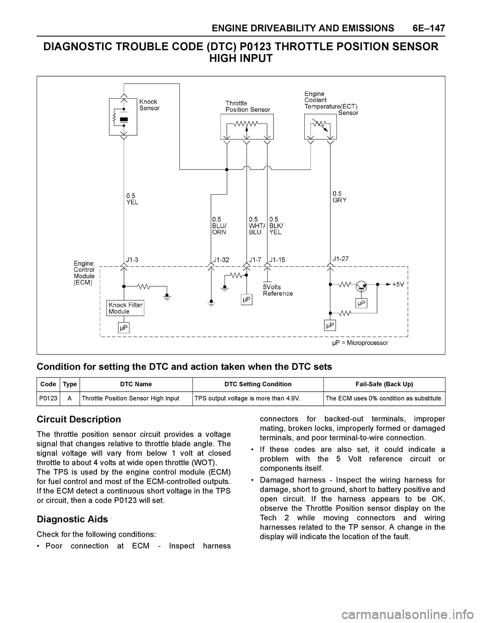
ENGINE DRIVEABILITY AND EMISSIONS 6E–147
DIAGNOSTIC TROUBLE CODE (DTC) P0123 THROTTLE POSITION SENSOR
HIGH INPUT
Condition for setting the DTC and action taken when the DTC sets
Circuit Description
The throttle position sensor circuit provides a voltage
signal that changes relative to throttle blade angle. The
signal voltage will vary from below 1 volt at closed
throttle to about 4 volts at wide open throttle (WOT).
The TPS is used by the engine control module (ECM)
for fuel control and most of the ECM-controlled outputs.
If the ECM detect a continuous short voltage in the TPS
or circuit, then a code P0123 will set.
Diagnostic Aids
Check for the following conditions:
Poor connection at ECM - Inspect harnessconnectors for backed-out terminals, improper
mating, broken locks, improperly formed or damaged
terminals, and poor terminal-to-wire connection.
If these codes are also set, it could indicate a
problem with the 5 Volt reference circuit or
components itself.
Damaged harness - Inspect the wiring harness for
damage, short to ground, short to battery positive and
open circuit. If the harness appears to be OK,
observe the Throttle Position sensor display on the
Tech 2 while moving connectors and wiring
harnesses related to the TP sensor. A change in the
display will indicate the location of the fault.
Code Type DTC Name DTC Setting Condition Fail-Safe (Back Up)
P0123 A Throttle Po sition Se nsor High Input TPS output v olta ge is mo re tha n 4.9V. The ECM uses 0% co nditio n as substitute.
Page 2727 of 4264
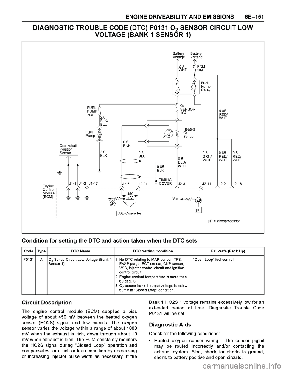
ENGINE DRIVEABILITY AND EMISSIONS 6E–151
DIAGNOSTIC TROUBLE CODE (DTC) P0131 O2 SENSOR CIRCUIT LOW
VOLTAGE (BANK 1 SENSOR 1)
Condition for setting the DTC and action taken when the DTC sets
Circuit Description
The engine control module (ECM) supplies a bias
voltage of about 450 mV between the heated ox ygen
sensor (HO2S) signal and low circuits. The ox ygen
sensor varies the voltage within a range of about 1000
mV when the ex haust is rich, down through about 10
mV when ex haust is lean. The ECM constantly monitors
the HO2S signal during “Closed Loop” operation and
compensates for a rich or lean condition by decreasing
or increasing injector pulse width as necessary. If theBank 1 HO2S 1 voltage remains ex cessively low for an
ex tended period of time, Diagnostic Trouble Code
P0131 will be set.
Diagnostic Aids
Check for the following conditions:
Heated oxygen sensor wiring - The sensor pigtail
may be routed incorrectly and/or contacting the
exhaust system. Also, check for shorts to ground,
shorts to battery positive and open circuits.
Code Type DTC Name DTC Setting Condition Fail-Safe (Back Up)
P0131 A O
2 SensorCircuit Low Voltage (Bank 1
Se nsor 1)1. No DTC re lating to MAP senso r, TPS,
EVAP purge, ECT sensor, CKP sensor,
VSS, injecto r contro l circuit and ignitio n
co ntro l circuit.
2. Engine coolant temperature is more than
60 de g. C.
3. O
2 sensor bank 1 output voltage is below
50mV in “Closed Loop” condition. “Ope n Lo op” fuel control.
Page 2731 of 4264
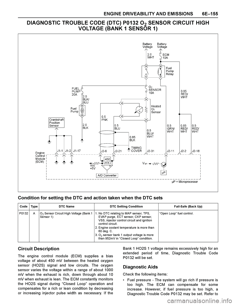
ENGINE DRIVEABILITY AND EMISSIONS 6E–155
DIAGNOSTIC TROUBLE CODE (DTC) P0132 O2 SENSOR CIRCUIT HIGH
VOLTAGE (BANK 1 SENSOR 1)
Condition for setting the DTC and action taken when the DTC sets
Circuit Description
The engine control module (ECM) supplies a bias
voltage of about 450 mV between the heated ox ygen
sensor (HO2S) signal and low circuits. The ox ygen
sensor varies the voltage within a range of about 1000
mV when the ex haust is rich, down through about 10
mV when ex haust is lean. The ECM constantly monitors
the HO2S signal during “Closed Loop” operation and
compensates for a rich or lean condition by decreasing
or increasing injector pulse width as necessary. If theBank 1 HO2S 1 voltage remains ex cessively high for an
ex tended period of time, Diagnostic Trouble Code
P0132 will be set.
Diagnostic Aids
Check the following items:
Fuel pressure - The system will go rich if pressure is
too high. The ECM can compensate for some
increase. However, if fuel pressure is too high, a
Diagnostic Trouble Code P0132 may be set. Refer to
Code Type DTC Name DTC Setting Condition Fail-Safe (Back Up)
P0132 A O
2 Se nsor Circuit High Volta ge (Ba nk 1
Se nsor 1)1. No DTC re lating to MAP senso r, TPS,
EVAP purge, ECT sensor, CKP sensor,
VSS, injecto r contro l circuit and ignitio n
co ntro l circuit.
2. Engine coolant temperature is more than
60 de g. C.
3. O
2 se nsor ba nk 1 output vo lta ge is mo re
than 952mV in “Clo se d Lo op” conditio n. “Ope n Lo op” fuel control.