2004 ISUZU TF SERIES fuel filter
[x] Cancel search: fuel filterPage 2529 of 4264
ENGINE FUEL (C24SE) 6C-5
Fuel Filter
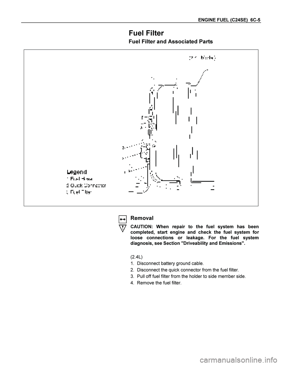
Fuel Filter and Associated Parts
Removal
CAUTION: When repair to the fuel system has been
completed, start engine and check the fuel system fo
r
loose connections or leakage. For the fuel system
diagnosis, see Section "Driveability and Emissions".
(2.4L)
1. Disconnect battery ground cable.
2. Disconnect the quick connector from the fuel filter.
3. Pull off fuel filter from the holder to side member side.
4. Remove the fuel filter.
Page 2530 of 4264
6C-6 ENGINE FUEL (C24SE)
Fuel Filter
Inspection
1. Replace the fuel filter if the fuel leaks from fuel filter
body or if the fuel filter body itself is damaged.
2. Replace the filter if it is clogged with dirt o
r
sediment.
Installation
1. Install the filter to holder from side member side.
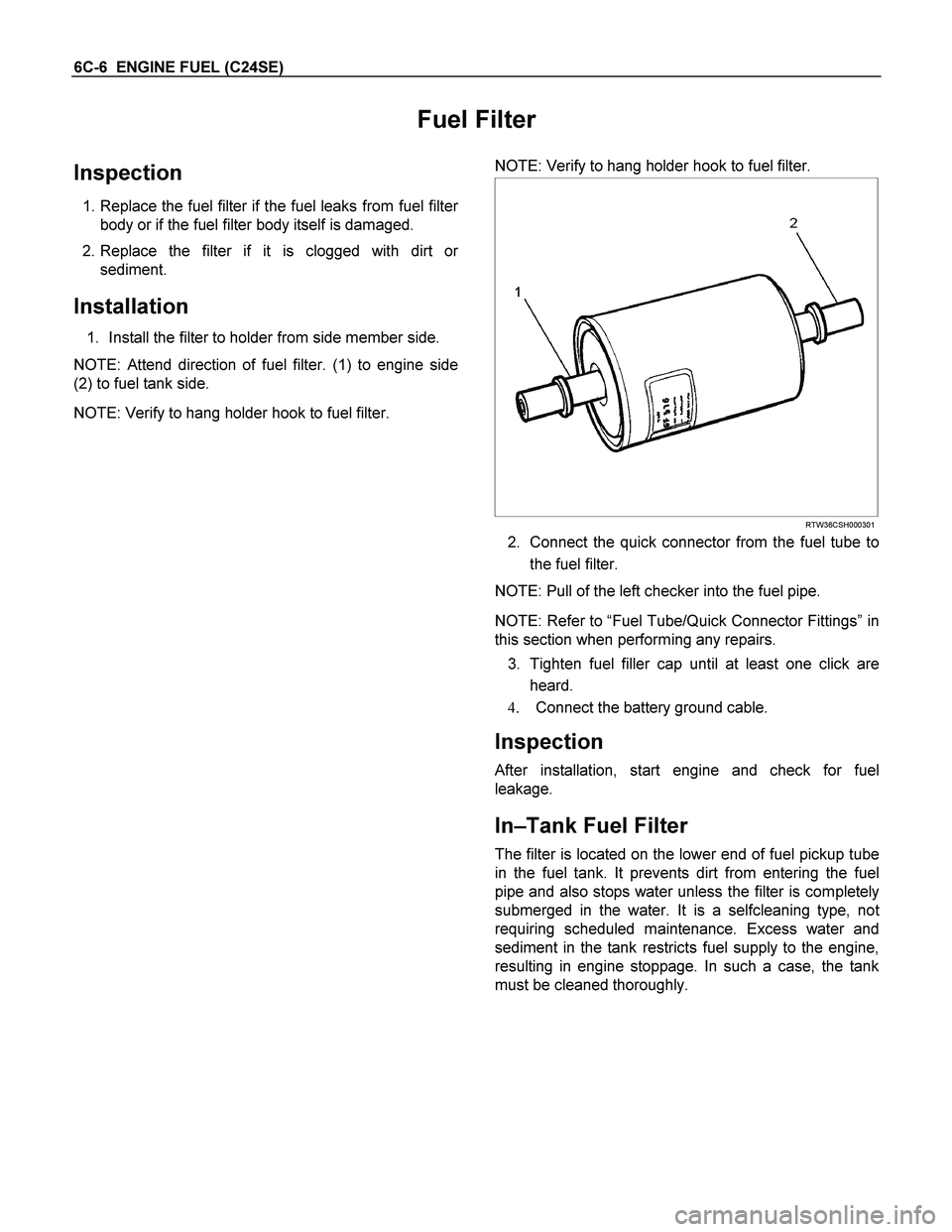
NOTE: Attend direction of fuel filter. (1) to engine side
(2) to fuel tank side.
NOTE: Verify to hang holder hook to fuel filter.
NOTE: Verify to hang holder hook to fuel filter.
RTW36CSH000301
2. Connect the quick connector from the fuel tube to
the fuel filter.
NOTE: Pull of the left checker into the fuel pipe.
NOTE: Refer to “Fuel Tube/Quick Connector Fittings” in
this section when performing any repairs.
3. Tighten fuel filler cap until at least one click are
heard.
4. Connect the battery ground cable.
Inspection
After installation, start engine and check for fuel
leakage.
In–Tank Fuel Filter
The filter is located on the lower end of fuel pickup tube
in the fuel tank. It prevents dirt from entering the fuel
pipe and also stops water unless the filter is completely
submerged in the water. It is a selfcleaning type, no
t
requiring scheduled maintenance. Excess water and
sediment in the tank restricts fuel supply to the engine,
resulting in engine stoppage. In such a case, the tank
must be cleaned thoroughly.
Page 2537 of 4264
ENGINE FUEL (C24SE) 6C-13
Fuel Tank
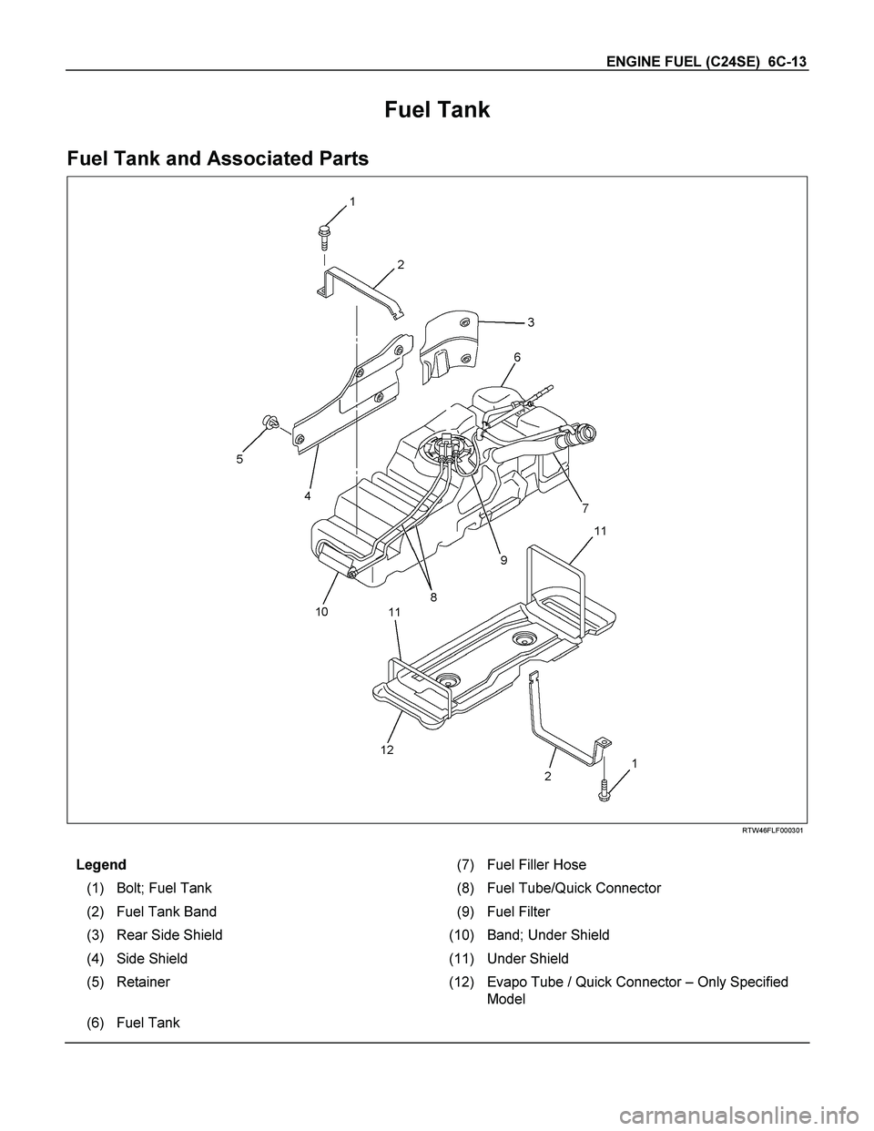
Fuel Tank and Associated Parts
RTW46FLF000301
Legend (7) Fuel Filler Hose
(1) Bolt; Fuel Tank (8)Fuel Tube/Quick Connector
(2) Fuel Tank Band (9)Fuel Filter
(3) Rear Side Shield (10)Band; Under Shield
(4) Side Shield (11)Under Shield
(5) Retainer (12)Evapo Tube / Quick Connector – Only Specified
Model
(6) Fuel Tank
Page 2628 of 4264
6E–52 ENGINE DRIVEABILITY AND EMISSIONS
GENERAL DESCRIPTION FOR FUEL
METERING
The fuel metering system starts with the fuel in the fuel
tank. An electric fuel pump, located in the fuel tank,
pumps fuel to the fuel rail through an in-line fuel filter.
The pump is designed to provide fuel at a pressure
above the pressure needed by the injectors.
A fuel pressure regulator in the fuel rail keeps fuel
available to the fuel injectors at a constant pressure.
A return line delivers unused fuel back to the fuel tank.
The basic function of the air/fuel metering system is to
control the air/fuel delivery to the engine. Fuel is
delivered to the engine by individual fuel injectors
mounted in the intake manifold.
The main control sensor is the heated ox ygen sensor
located in the ex haust system. The heated ox ygen
sensor reports to the ECM how much oxygen is in the
ex haust gas. The ECM changes the air/fuel ratio to the
engine by controlling the amount of time that fuel
injector is “On”.
The best mix ture to minimize exhaust emissions is 14.7
parts of air to 1 part of gasoline by weight, which allows
the catalytic converter to operate most efficiently.
Because of the constant measuring and adjusting of the
air/fuel ratio, the fuel injection system is called a “closed
loop” system.
The ECM monitors signals from several sensors in
order to determine the fuel needs of the engine. Fuel is
delivered under one of several conditions called “mode”.
All modes are controlled by the ECM.
Battery Voltage Correction Mode
When battery voltage is low, the ECM will compensate
for the weak spark by increasing the following:
The amount of fuel delivered.
The idle RPM.
Clear Flood Mode
Clear a flooded engine by pushing the accelerator pedal
down all the way. The ECM then de-energizes the fuel
injectors. The ECM holds the fuel injectors de-energized
as long as the throttle remains above 75% and the
engine speed is below 800 RPM. If the throttle position
becomes less than 75%, the ECM again begins to pulse
the injectors ON and OFF, allowing fuel into the
cylinders.
Deceleration Fuel Cutoff (DFCO) Mode
The ECM reduces the amount of fuel injected when it
detects a decrease in the throttle position and the air
flow. When deceleration is very fast, the ECM may cut
off fuel completely. Until enable conditions meet the
engine revolution less 1000 rpm or manifold absolute
pressure less than 10 kPa.
Engine Speed/ Vehicle Speed/ Fuel Disable
Mode
The ECM monitors engine speed. It turns off the fuel
injectors when the engine speed increases above 6000
RPM. The fuel injectors are turned back on when
engine speed decreases below 3500 RPM.
Acceleration Mode
The ECM provides ex tra fuel when it detects a rapid
increase in the throttle position and the air flow.
Fuel Cutoff Mode
No fuel is delivered by the fuel injectors when the
ignition is OFF. This prevents engine run-on. In addition,
the ECM suspends fuel delivery if no reference pulses
are detected (engine not running) to prevent engine
flooding.
Starting Mode
When the ignition is first turned ON, the ECM energizes
the fuel pump relay for two seconds to allow the fuel
pump to build up pressure. The ECM then checks the
engine coolant temperature (ECT) sensor and the
throttle position sensor to determine the proper air/fuel
ratio for starting.
The ECM controls the amount of fuel delivered in the
starting mode by adjusting how long the fuel injectors
are energized by pulsing the injectors for very short
times.
Run Mode
The run mode has the following two conditions:
Open loop
Closed loop
When the engine is first started, the system is in “open
loop” operation. In “Open Loop,” the ECM ignores the
signal from the heated oxygen sensor (HO2S). It
calculates the air/fuel ratio based on inputs from the TP,
ECT, and MAP sensors.
The system remains in “Open Loop” until the following
conditions are met:
The HO2S has a varying voltage output showing that
it is hot enough to operate properly (this depends on
temperature).
The ECT has reached a specified temperature.
A specific amount of time has elapsed since starting
the engine.
Engine speed has been greater than a specified RPM
since start-up.
The specific values for the above conditions vary with
different engines and are stored in the programmable
read only memory (PROM). When these conditions are
met, the system enters “closed loop” operation. In
“closed loop,” the ECM calculates the air/fuel ratio
(injector on-time) based on the signal from the HO2S.
This allows the air/fuel ratio to stay very close to 14.7:1.
Page 2643 of 4264
ENGINE DRIVEABILITY AND EMISSIONS 6E–67
GENERAL SERVICE INFORMATION
Aftermarket Electrical and Vacuum
Equipment
Aftermarket (add-on) electrical and vacuum equipment
is defined as any equipment which connects to the
vehicle's electrical or vacuum systems that is installed
on a vehicle after it leaves the factory. No allowances
have been made in the vehicle design for this type of
equipment.
NOTE: No add-on vacuum equipment should be added
to this vehicle.
NOTE: Add-on electrical equipment must only be
connected to the vehicle's electrical system at the
battery (power and ground).
Add-on electrical equipment, even when installed to
these guidelines, may still cause the electric system to
malfunction. This may also include equipment not
connected to the vehicle electrical system such as
portable telephones and radios. Therefore, the first step
in diagnosing any electric problem is to eliminate all
aftermarket electrical equipment from the vehicle. After
this is done, if the problem still ex ists, it may be
diagnosed in the normal manner.
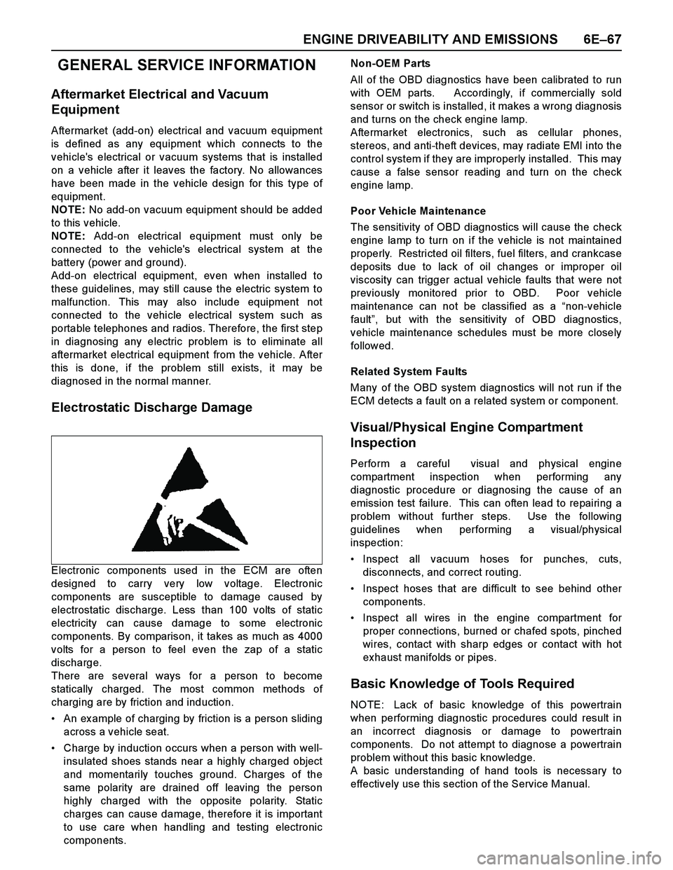
Electrostatic Discharge Damage
Electronic components used in the ECM are often
designed to carry very low voltage. Electronic
components are susceptible to damage caused by
electrostatic discharge. Less than 100 volts of static
electricity can cause damage to some electronic
components. By comparison, it takes as much as 4000
volts for a person to feel even the zap of a static
discharge.
There are several ways for a person to become
statically charged. The most common methods of
charging are by friction and induction.
An ex ample of charging by friction is a person sliding
across a vehicle seat.
Charge by induction occurs when a person with well-
insulated shoes stands near a highly charged object
and momentarily touches ground. Charges of the
same polarity are drained off leaving the person
highly charged with the opposite polarity. Static
charges can cause damage, therefore it is important
to use care when handling and testing electronic
components.Non-OEM Parts
All of the OBD diagnostics have been calibrated to run
with OEM parts. Accordingly, if commercially sold
sensor or switch is installed, it makes a wrong diagnosis
and turns on the check engine lamp.
Aftermarket electronics, such as cellular phones,
stereos, and anti-theft devices, may radiate EMI into the
control system if they are improperly installed. This may
cause a false sensor reading and turn on the check
engine lamp.
Poor Vehicle Maintenance
The sensitivity of OBD diagnostics will cause the check
engine lamp to turn on if the vehicle is not maintained
properly. Restricted oil filters, fuel filters, and crankcase
deposits due to lack of oil changes or improper oil
viscosity can trigger actual vehicle faults that were not
previously monitored prior to OBD. Poor vehicle
maintenance can not be classified as a “non-vehicle
fault”, but with the sensitivity of OBD diagnostics,
vehicle maintenance schedules must be more closely
follow ed.
Related System Faults
Many of the OBD system diagnostics will not run if the
ECM detects a fault on a related system or component.
Visual/Physical Engine Compartment
Inspection
Perform a careful visual and physical engine
compartment inspection when performing any
diagnostic procedure or diagnosing the cause of an
emission test failure. This can often lead to repairing a
problem without further steps. Use the following
guidelines when performing a visual/physical
inspection:
Inspect all vacuum hoses for punches, cuts,
disconnects, and correct routing.
Inspect hoses that are difficult to see behind other
components.
Inspect all wires in the engine compartment for
proper connections, burned or chafed spots, pinched
wires, contact with sharp edges or contact with hot
exhaust manifolds or pipes.
Basic Knowledge of Tools Required
NOTE: Lack of basic knowledge of this powertrain
when performing diagnostic procedures could result in
an incorrect diagnosis or damage to powertrain
components. Do not attempt to diagnose a powertrain
problem without this basic knowledge.
A basic understanding of hand tools is necessary to
effectively use this section of the Service Manual.
Page 2684 of 4264
6E–108 ENGINE DRIVEABILITY AND EMISSIONS
FUEL SYSTEM DIAGNOSIS
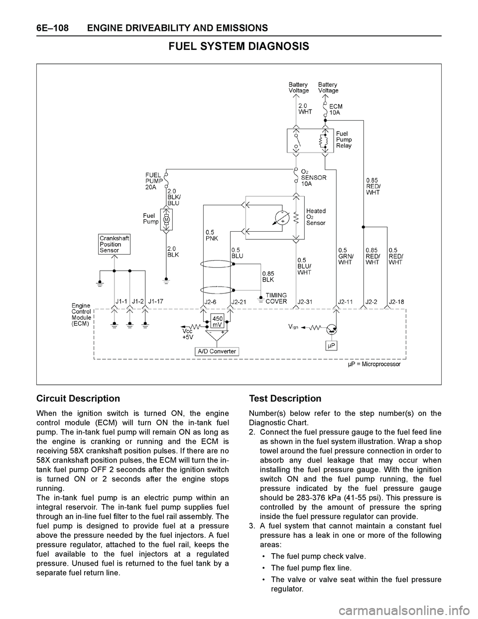
Circuit Description
When the ignition switch is turned ON, the engine
control module (ECM) will turn ON the in-tank fuel
pump. The in-tank fuel pump will remain ON as long as
the engine is cranking or running and the ECM is
receiving 58X crankshaft position pulses. If there are no
58X crankshaft position pulses, the ECM will turn the in-
tank fuel pump OFF 2 seconds after the ignition switch
is turned ON or 2 seconds after the engine stops
running.
The in-tank fuel pump is an electric pump within an
integral reservoir. The in-tank fuel pump supplies fuel
through an in-line fuel filter to the fuel rail assembly. The
fuel pump is designed to provide fuel at a pressure
above the pressure needed by the fuel injectors. A fuel
pressure regulator, attached to the fuel rail, keeps the
fuel available to the fuel injectors at a regulated
pressure. Unused fuel is returned to the fuel tank by a
separate fuel return line.
Test Description
Number(s) below refer to the step number(s) on the
Diagnostic Chart.
2. Connect the fuel pressure gauge to the fuel feed line
as shown in the fuel system illustration. Wrap a shop
towel around the fuel pressure connection in order to
absorb any duel leakage that may occur when
installing the fuel pressure gauge. With the ignition
switch ON and the fuel pump running, the fuel
pressure indicated by the fuel pressure gauge
should be 283-376 kPa (41-55 psi). This pressure is
controlled by the amount of pressure the spring
inside the fuel pressure regulator can provide.
3. A fuel system that cannot maintain a constant fuel
pressure has a leak in one or more of the following
areas:
The fuel pump check valve.
The fuel pump flex line.
The valve or valve seat within the fuel pressure
regulator.
Page 2686 of 4264
6E–110 ENGINE DRIVEABILITY AND EMISSIONS
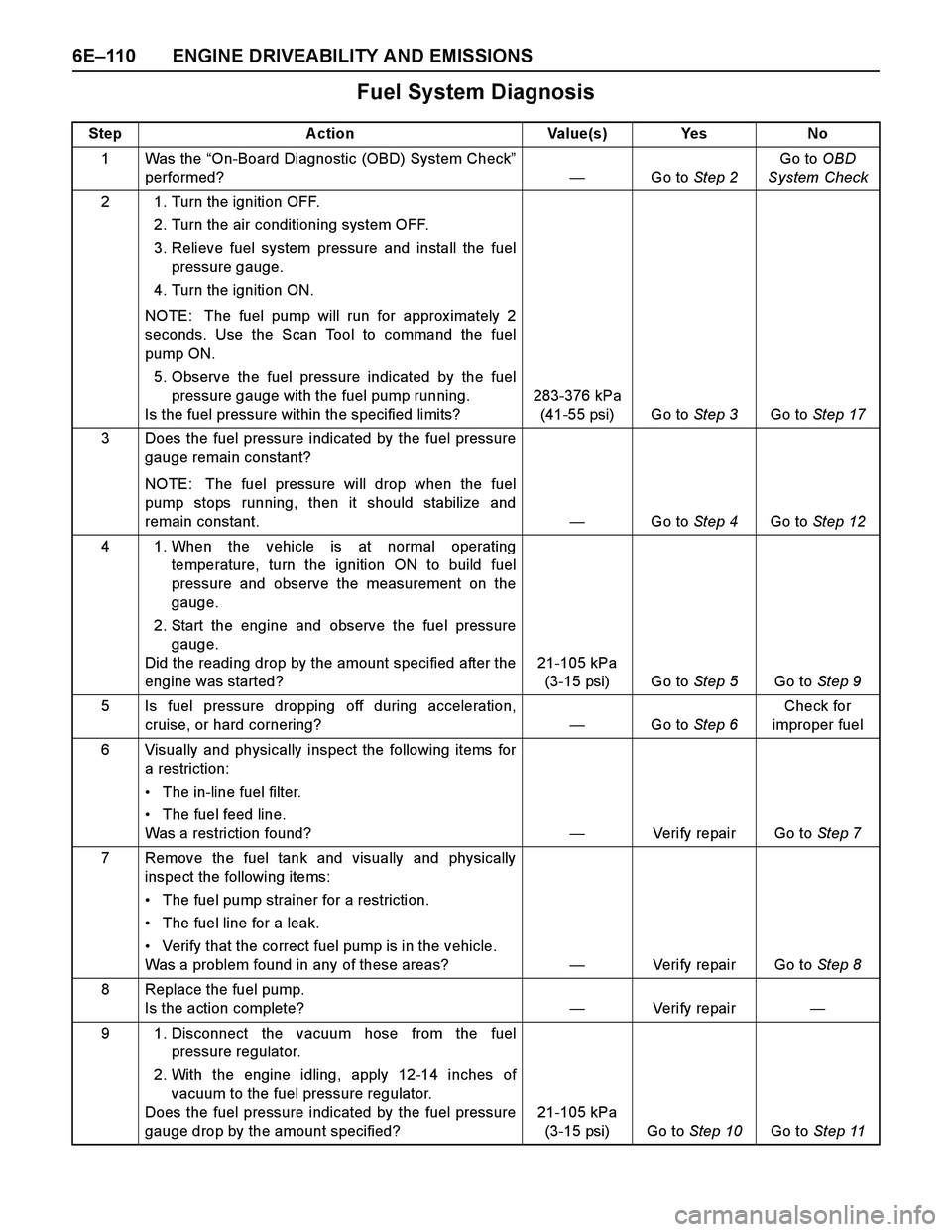
Fuel System Diagnosis
Step Action Value(s) Yes No
1Was the “On-Board Diagnostic (OBD) System Check”
performed?—Go to Step 2Go to OBD
System Check
2 1. Turn the ignition OFF.
2. Turn the air conditioning system OFF.
3. Relieve fuel system pressure and install the fuel
pressure gauge.
4. Turn the ignition ON.
NOTE: The fuel pump will run for approx imately 2
seconds. Use the Scan Tool to command the fuel
pump ON.
5. Observe the fuel pressure indicated by the fuel
pressure gauge with the fuel pump running.
Is the fuel pressure within the specified limits?283-376 kPa
(41-55 psi) Go to Step 3Go to Step 17
3 Does the fuel pressure indicated by the fuel pressure
gauge remain constant?
NOTE: The fuel pressure will drop when the fuel
pump stops running, then it should stabilize and
remain constant.—Go to Step 4Go to Step 12
4 1. When the vehicle is at normal operating
temperature, turn the ignition ON to build fuel
pressure and observe the measurement on the
gauge.
2. Start the engine and observe the fuel pressure
gauge.
Did the reading drop by the amount specified after the
engine was started?21-105 kPa
(3-15 psi) Go to Step 5Go to Step 9
5 Is fuel pressure dropping off during acceleration,
cruise, or hard cornering?—Go to Step 6Check for
improper fuel
6 Visually and physically inspect the following items for
a restriction:
The in-line fuel filter.
The fuel feed line.
Was a restriction found?—Verify repair Go to Step 7
7 Remove the fuel tank and visually and physically
inspect the following items:
The fuel pump strainer for a restriction.
The fuel line for a leak.
Verify that the correct fuel pump is in the vehicle.
Was a problem found in any of these areas?—Verify repair Go to Step 8
8 Replace the fuel pump.
Is the action complete?—Veri fy repai r—
9 1. Disconnect the vacuum hose from the fuel
pressure regulator.
2. With the engine idling, apply 12-14 inches of
vacuum to the fuel pressure regulator.
Does the fuel pressure indicated by the fuel pressure
gauge drop by the amount specified?21-105 kPa
(3-15 psi) Go to Step 10Go to Step 11
Page 2790 of 4264
6E–214 ENGINE DRIVEABILITY AND EMISSIONS
DIAGNOSTIC TROUBLE CODE (DTC) P1171 FUEL SUPPLY SYSTEM LEAN
DURING POWER ENRICHMENT
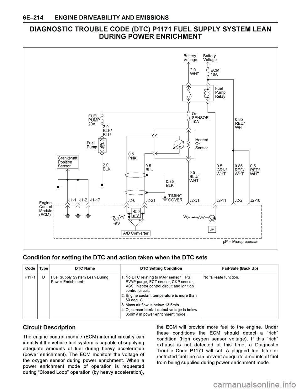
Condition for setting the DTC and action taken when the DTC sets
Circuit Description
The engine control module (ECM) internal circuitry can
identify if the vehicle fuel system is capable of supplying
adequate amounts of fuel during heavy acceleration
(power enrichment). The ECM monitors the voltage of
the ox ygen sensor during power enrichment. When a
power enrichment mode of operation is requested
during “Closed Loop” operation (by heavy acceleration),the ECM will provide more fuel to the engine. Under
these conditions the ECM should detect a “rich”
condition (high ox ygen sensor voltage). If this “rich”
ex haust is not detected at this time, a Diagnostic
Trouble Code P1171 will set. A plugged fuel filter or
restricted fuel line can prevent adequate amounts of fuel
from being supplied during power enrichment mode.
Code Type DTC Name DTC Setting Condition Fail-Safe (Back Up)
P1171 D Fuel Supply System Lean During
Po wer Enrichment 1. No DTC re lating to MAP senso r, TPS,
EVAP purge, ECT sensor, CKP sensor,
VSS, injecto r contro l circuit and ignitio n
co ntro l circuit.
2. Engine coolant temperature is more than
60 de g. C.
3. Ma ss a ir flo w is below 13.5m/s.
4. O
2 sensor bank 1 output voltage is below
350mV in power enrichment mode. No fail-safe function.